Key Points
- •
There are three standard imaging windows in cardiac ultrasound imaging: parasternal, apical, and subcostal. From these three windows, the 12 traditional imaging views are obtained.
- •
Providers should visualize cardiac structures in at least two imaging planes to make accurate assessments.
- •
The core skills of cardiac ultrasound are image acquisition and image interpretation, both of which must be mastered before clinical integration can be learned.
Background
Point-of-care ultrasound assessment of the heart is an extremely useful and powerful tool in the hands of competent providers. Because cardiac ultrasound requires assessment of both structure and function, high-quality images must be acquired for accurate assessment. In order to be confident in the interpretation of a cardiac ultrasound exam, images from two or more imaging planes should ideally be obtained, which increases the complexity of the exam. A significant investment of time is required to master the techniques described in this chapter.
Novice ultrasonographers can find solace in the fact that after learning the basic transducer positions, provider skill level and confidence generally increase rapidly. New users can become comfortable with cardiac ultrasonography relatively quickly if supervision is adequate and enough time is devoted to structured practice. It is recommended to focus on achieving proficiency in five core cardiac views: parasternal long-axis, parasternal short-axis (mid-ventricular level), apical 4-chamber, subcostal 4-chamber, and subcostal inferior vena cava (IVC).
Anatomy: Imaging Windows, Planes, and Views
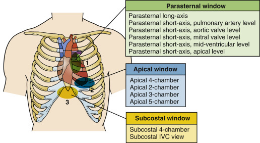
An imaging window refers to an anatomic position on the patient’s body where an ultrasound transducer is placed to visualize specific structures. For transthoracic cardiac ultrasound exams, there are three standard imaging windows: parasternal, apical, and subcostal ( Figure 13.1 ).
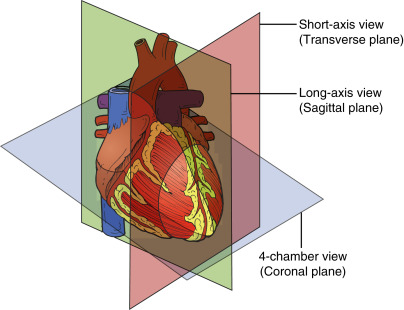
An imaging plane refers to an anatomic plane, namely, sagittal, coronal, or transverse, along which the ultrasound beam is aligned. All objects, unless they are perfectly symmetric, have a long and short axis. In the heart, imaging planes are named in relation to axes of the heart, and four planes are conventionally described: long-axis, short-axis, 4-chamber, and 2-chamber. The long-axis plane bisects the heart vertically from the left ventricular apex to the aortic valve (AV) at the base of the heart. The short-axis plane is perpendicular to the long axis and generates cross sections of the ventricles. Similarly, the 4-chamber plane extends from the apex to base of the heart but bisects the tricuspid valve (TV) and mitral valve (MV). The 2-chamber plane is perpendicular to the 4-chamber plane ( Figure 13.2 ). Between the long and short axes of the heart, an infinite number of oblique planes exist that are not conventionally named.
Combining imaging windows and planes gives rise to imaging views . Imaging views are standard cross sections of the heart obtained from specific windows. Within each imaging window, there are several different imaging views that can be acquired along the different imaging planes. Imaging views are named according to the window and plane. For example, in the parasternal window, the two principal views are the parasternal long-axis view and parasternal short-axis view.
The human thorax, with its bony ribs and air-filled lungs, is a naturally challenging environment for sound waves to reach deeper structures like the heart. Despite these challenges, the fundamental views of a transthoracic exam are attainable in most patients from the parasternal, apical, and subcostal windows. Each of these windows is explored in detail in this chapter. Specific clinical questions may occasionally mandate use of other windows, such as the suprasternal window to evaluate the aortic arch, but these views are not part of a standard point-of-care exam. Inability to acquire satisfactory images occurs in a minority of patients, and a transesophageal echocardiogram may be required for an adequate assessment of the heart in such cases.
Transducer Movements
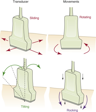
Understanding the conventional nomenclature describing transducer movements is important both to understand the descriptions below and to communicate with colleagues. There are four primary movements of the transducer: sliding, rotating, tilting, and rocking ( Figure 13.3 ).
- 1.
Sliding refers to relocating the transducer on the skin surface; it is the process of physically moving the point of contact between the transducer and skin.
- 2.
Rotating refers to twisting the transducer on its central axis, like a corkscrew.
- 3.
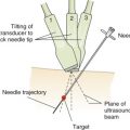
Tilting , also called sweeping, fanning, or angling, refers to changing the angle of the imaging plane while maintaining the point of contact with the skin surface. Tilting allows visualization of serial cross-sectional images of a structure from a single acoustic window, such as tilting the transducer from the cardiac base to apex to acquire serial parasternal short-axis views. This “cross-plane” movement allows the provider to sweep through a structure of interest from left to right, or superior to inferior.
- 4.
Rocking refers to aiming the ultrasound beam either toward or away from the transducer orientation marker, or notch, while maintain the point of contact with the skin surface. This “in-plane” movement allows centering of the image on the screen without changing the imaging plane and allows visualization beyond the current field of view in a specific direction.
Point-of-Care Ultrasound Perspective
The number of possible cardiac imaging views can seem limitless at first glance, but the quantity of conventionally defined views is quite limited. From the three traditional imaging windows, 12 traditional imaging views are associated with a transthoracic cardiac ultrasound exam (see Figure 13.1 ).
From a point-of-care perspective, five imaging views must be mastered to answer the vast majority of clinically relevant questions:
- 1.
Parasternal long-axis view (PLAX)
- 2.
Parasternal short-axis, mid-ventricular level view (PSAX)
- 3.
Apical 4-chamber view (A4C)
- 4.
Subcostal 4-chamber view (S4C)
- 5.
Subcostal IVC view
Parasternal Window
Imaging Window
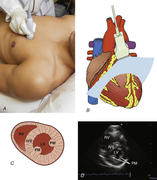
Image acquisition traditionally begins in the parasternal window. An advantage of the parasternal window is the ability to acquire high-quality images in most patients regardless of position. Ideally, the patient should be supine and can be rotated partially or fully to a left lateral decubitus position to proximate the heart to the chest wall. Most critically ill patients cannot be placed in a full left lateral decubitus position, but satisfactory images can usually be obtained from a supine or semi-rotated position. Alternate imaging windows may provide higher-quality images in patients with a more inferiorly located heart, such as those with chronic obstructive pulmonary disease.
A phased-array transducer should be placed immediately to the left of the sternum in the third or fourth intercostal space with the transducer orientation marker pointed to the patient’s right shoulder. The optimal window may be located anywhere between the second and fifth intercostal spaces, and providers should slide the transducer to an intercostal space above or below the current position if quality images are not attainable. The transducer should be held in position at the left sternal border at all times.
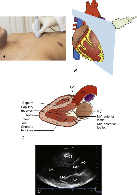
Parasternal Long-Axis View
From the parasternal position, the probe should be adjusted so that the transducer orientation marker is pointing toward the patient’s right shoulder ( Figure 13.4 ). The ultrasound beam should be positioned parallel to a line running from the patient’s right shoulder to their left hip. Images obtained represent anatomic cross sections through the long axis of the heart, with the apical portion to the left of the screen and base to the right. The right ventricle (RV) is seen anteriorly, at the top of the screen.
The ideal view is obtained once both the AV and MV are clearly visualized and positioned just to the right of center on the screen. The transducer is tilted until the base of the heart comes into view; slight rotation of the transducer opens the left ventricular cavity to its fullest extent, avoiding the tendency to foreshorten the cavity. This common error, referred to as the cylinder effect , results in overestimation of systolic function of the left ventricle (LV) and underestimation of LV cavity dimension. Additional subtle tilting or angling may be required to optimize the image. If a good-quality image cannot be achieved, it may be helpful to slide the transducer position up or down one intercostal space and begin anew. Alternatively, the patient may be repositioned, where turning the patient further toward the left lateral decubitus position is frequently helpful. Finally, cooperative patients may be asked to consciously regulate their respiratory cycle, with attempts to capture images at end-inspiration or end-expiration.
Key structures that must be identified in the parasternal long-axis view include AV, MV, LV, pericardium (both anterior and posterior to the heart), RV, left ventricular outflow tract (LVOT), and portions of the ascending and descending thoracic aorta.
In the context of point-of-care ultrasound, the parasternal long-axis view is used primarily to assess left ventricular size and function, the aortic and mitral valves, and left atrial size. Although imaging is limited to visualization of the anteroseptal and inferolateral LV walls, left ventricular systolic function can generally be accurately assessed in this view. Pericardial effusions can also be detected, especially when circumferential. Providers cannot reliably comment on RV size or function because only a small cross section of the RV is seen in this view; however, a severely dilated RV will often be detected. The parasternal long-axis view provides basic information related to the assessment of aortic and mitral valves and allows evaluation for dynamic obstruction at the level of the LVOT.
Parasternal Short-Axis View
The most effective way to rapidly acquire high-quality short-axis images from the parasternal window is to start with a high-quality parasternal long-axis image. The transducer is centered over the MV in a parasternal long-axis view, and then rotated 90 degrees clockwise to point the transducer orientation marker toward the patient’s left shoulder. Care should be taken to avoid sliding the transducer into a different position on the chest. Two hands should be used for a smooth transition from long-axis to short-axis views, with one hand rotating the transducer and the other hand stabilizing the transducer on the skin surface ( Figure 13.5 ).