Outline
Topic 7, Figure 239
- 1.
Fig. 239 . Topic: Tomographic Ultrasound Imaging (TUI) of the Abnormal Transperineal Anal Sphincter Complex (ASC) 3D Volume Set
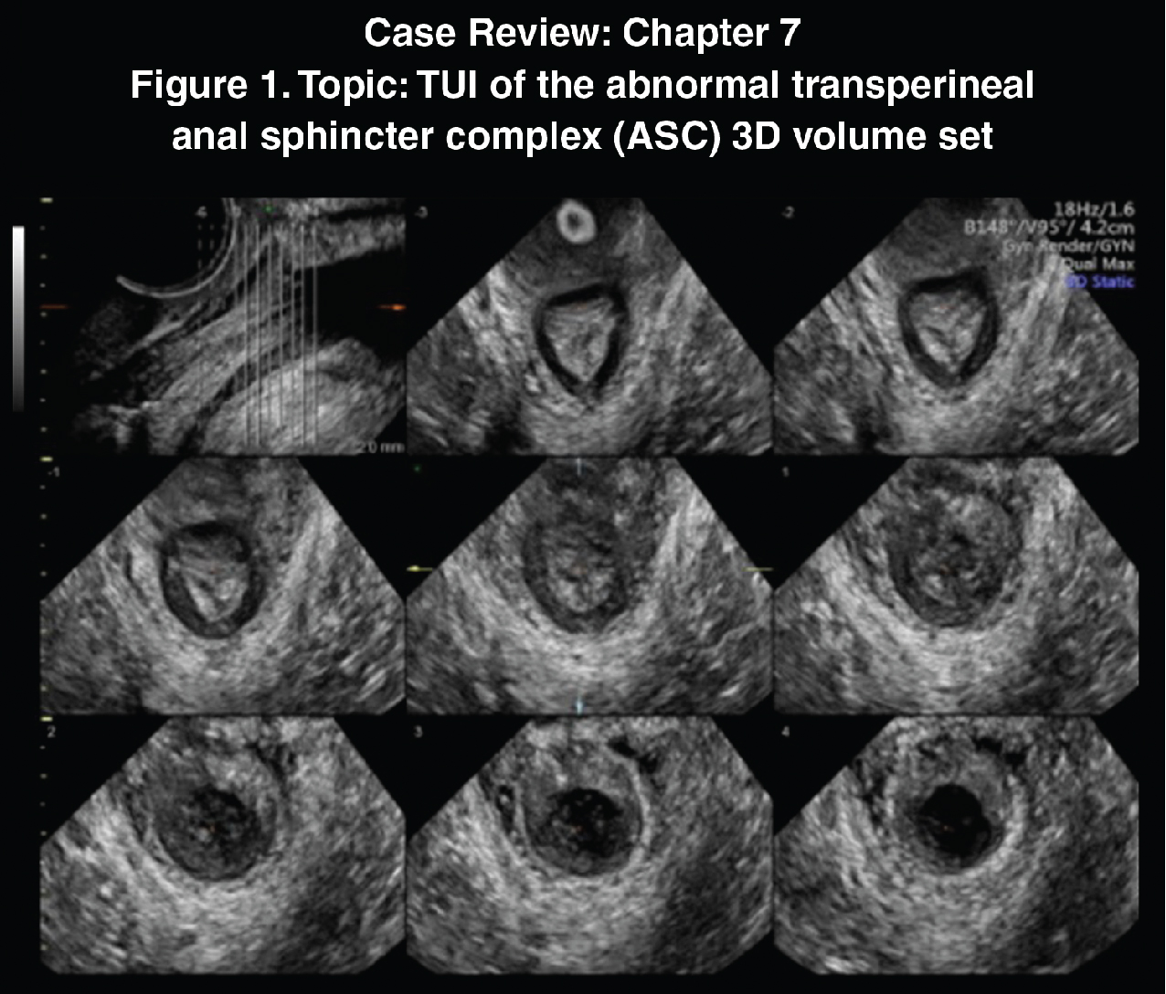
Fig. 239
When the ASC is abnormal, the use of TUI may illuminate the overall abnormal anatomic changes by demonstrating consistent proximal to distal cuts through the area in any plane. In this case, the axial cuts, made of 1-mm segments, demonstrate abnormal mid to distal changes of the internal anal sphincter and external anal sphincter integrity beginning at the mid central cut –3 to cut 3.
Case 112, Figure 240
- 2.
Fig. 240 demonstrates two transperineal 3D rendered images of a normal suburethral sling, each with a different post-processed image type. Though the goal of surgery is to place the urethral sling posterior to the mid-urethral level, imaging may be utilized to determine at what level it is actually located; therefore, these imaging cases will generically call it “suburethral.” The image on the left is a chroma-enhanced image and the one on the right is a tissue-enhanced image. Although the information is the same for each image, perception may be altered, and anatomy clarified with the type of post-processing at the time of the exam or later at the workstation. Instrumentation tools allow the examiner to manipulate the images on any axis, with any chroma type or any degree of individualized preference. Take the time to most optimally utilize the special functions on your ultrasound system.
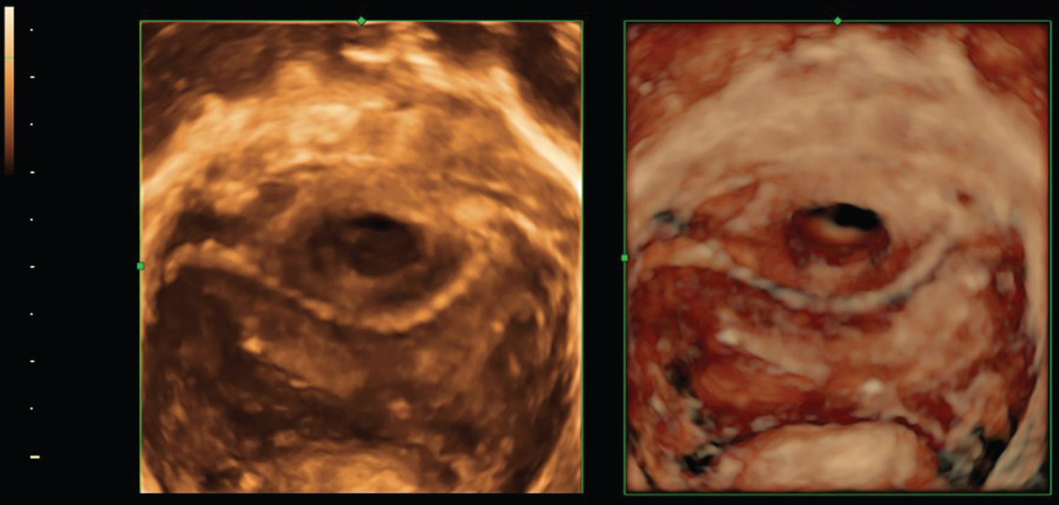
Fig. 240
The slight asymmetry of each side of the sling is within normal limits in appearance. Notice that the sling appears centrally positioned posterior to the urethra, although without the A plane of the 3D volume set, one cannot determine if it is located at the mid-urethra.
Answer the following questions.
- a.
Which appears crisper? _____
- b.
Which demonstrates visualization of the urethra better? _____
- c.
Which demonstrates visualization of the vagina better? _____
- d.
Which demonstrates the sling better? _____
- a.
Case 113, Figures 241–243
- 3.
Figs. 241 and 242 represent transperineal 3D volume set images using a 6–12 MHz endovaginal (EV) transducer of a 52-year-old patient who had unsuccessful placement of a urethral sling at an outside institution, which was ultimately “removed.” In addition to her ongoing discomfort, she has returned to a urinary incontinence status.
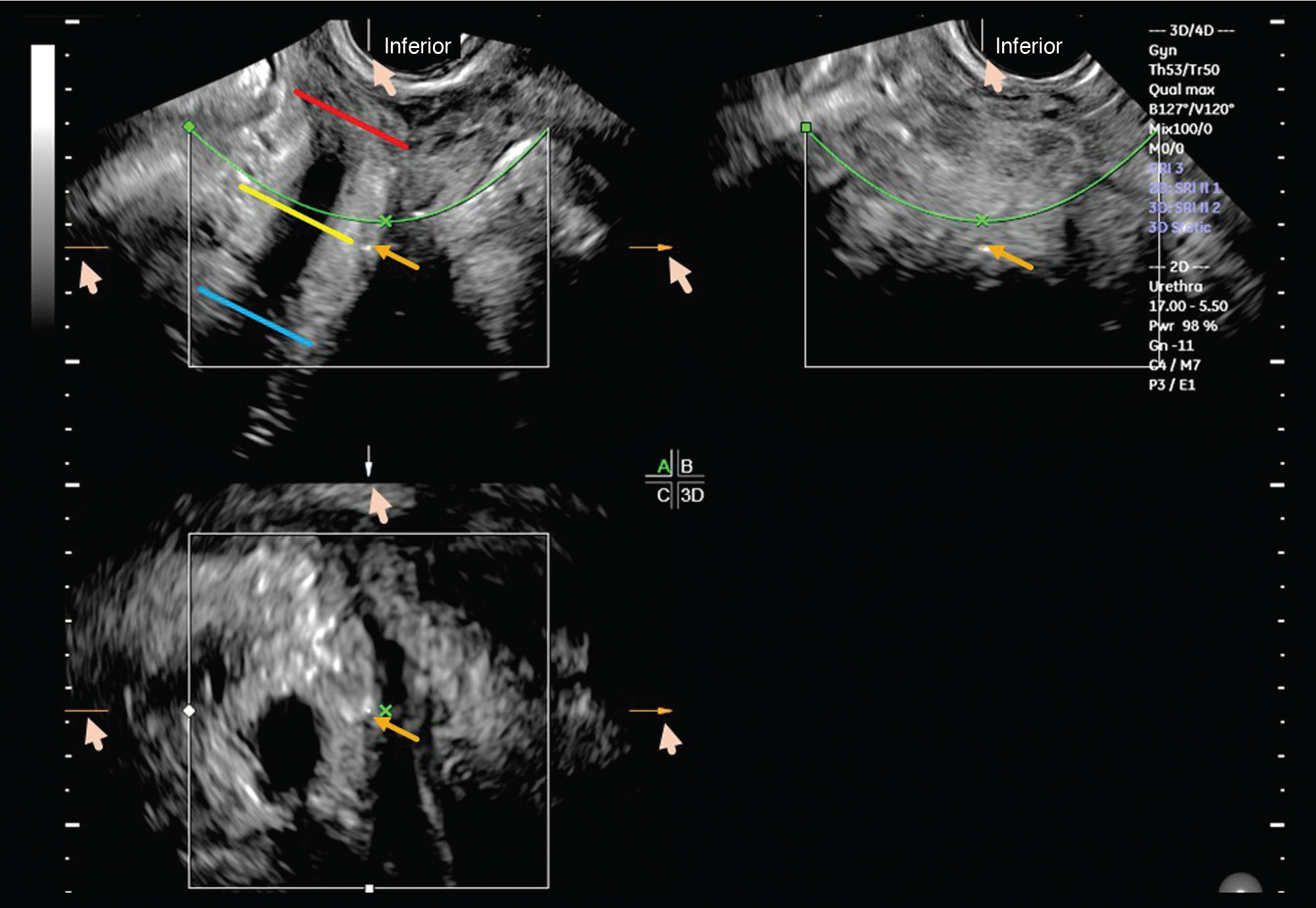
Fig. 241
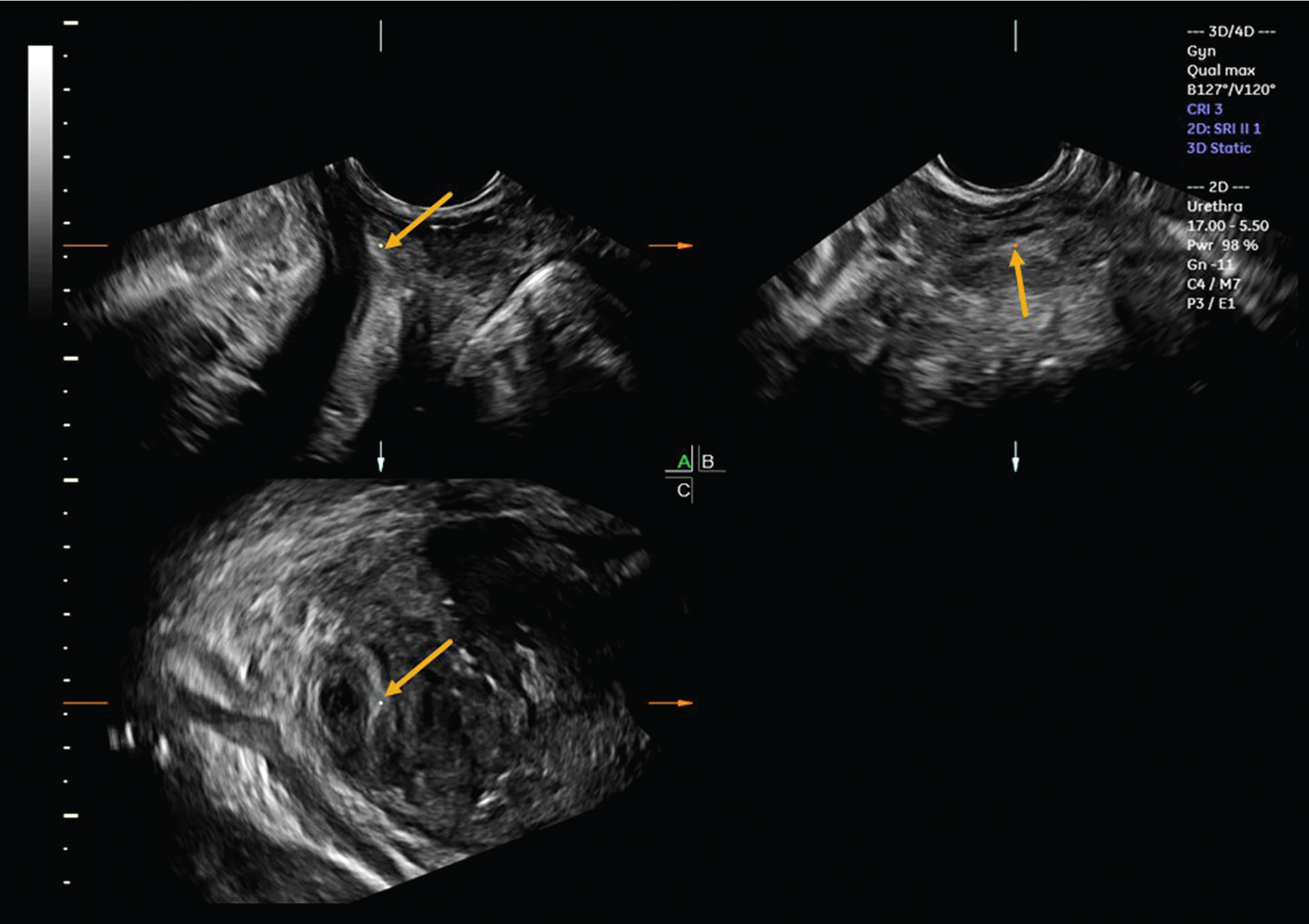
Fig. 242
Ideally, the mesh would be placed at the midlevel. Fig. 241 is a 3D volume set where the center reference point (CRP; gold arrows) is placed on which location below?
- a.
Proximal posterior urethral wall
- b.
Proximal anterior urethral wall
- c.
Mid anterior vaginal wall
- d.
Mid posterior vaginal wall
- e.
Distal posterior urethral wall
- f.
Distal anterior urethral wall
- a.
- 4.
Fig. 241 . With any standard pelvic floor 3D volume set, the anatomical cuts seen on the three orthogonal planes are relative to CRP placement, so it is operator dependent. Furthermore, with the line of reference brought from the top of the screen to the CRP and if residual mesh is present, it would be seen on the rendered image as a curvilinear suburethral structure and as an echogenic focus on the plane at the sagittal mid-urethral level and most optimally on the C plane. (The rendered image has been removed). Considering that the length of a urethra is approximately 4 cm, it is understandable that the mesh presence may not be appreciated at all even with a 1 cm error in CRP placement (see proximal, mid, and distal levels on the A plane at the blue, yellow, and red lines). Is there mesh seen at the midlevel? _____
- 5.
The CRP (seen as the white, red, and light blue dots) on all three orthogonal planes on Fig. 241 was moved inferiorly on the volume set of Fig. 242 (gold arrows toward the top of the screen, which is inferior on the patient) and demonstrates how the diagnosis can be completely altered by changing where the CRP is placed. Remember, the ultrasound system will give you another place to see those intersecting center reference points with the partial arrows on the edges of each plane (pink arrows), no matter to where the CRP is moved. If residual mesh is present at this level, it would be seen. Is there mesh seen at this level? _____
- 6.
At which location below is the CRP placed on Fig. 242 ?
- a.
Proximal posterior urethral wall
- b.
Proximal anterior urethral wall
- c.
Mid posterior wall
- d.
Mid anterior urethral wall
- e.
Distal posterior urethral wall
- f.
Proximal anterior urethra wall
- g.
Proximal posterior urethral wall
- a.
The post-processed Fig. 243 is the C plane, now rotated upright on the Z-axis with the CRP (white dot; red arrow) seen at the residual mesh, extending along the mid to left lateral side of the proximal urethra (green arrows). Without visualization of a right mesh aspect (gold arrow), it was theoretically partially resected.
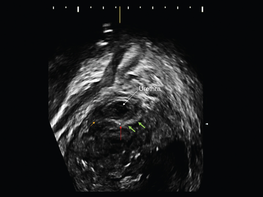
Fig. 243
Case 114, Figures 244–246
- 7.
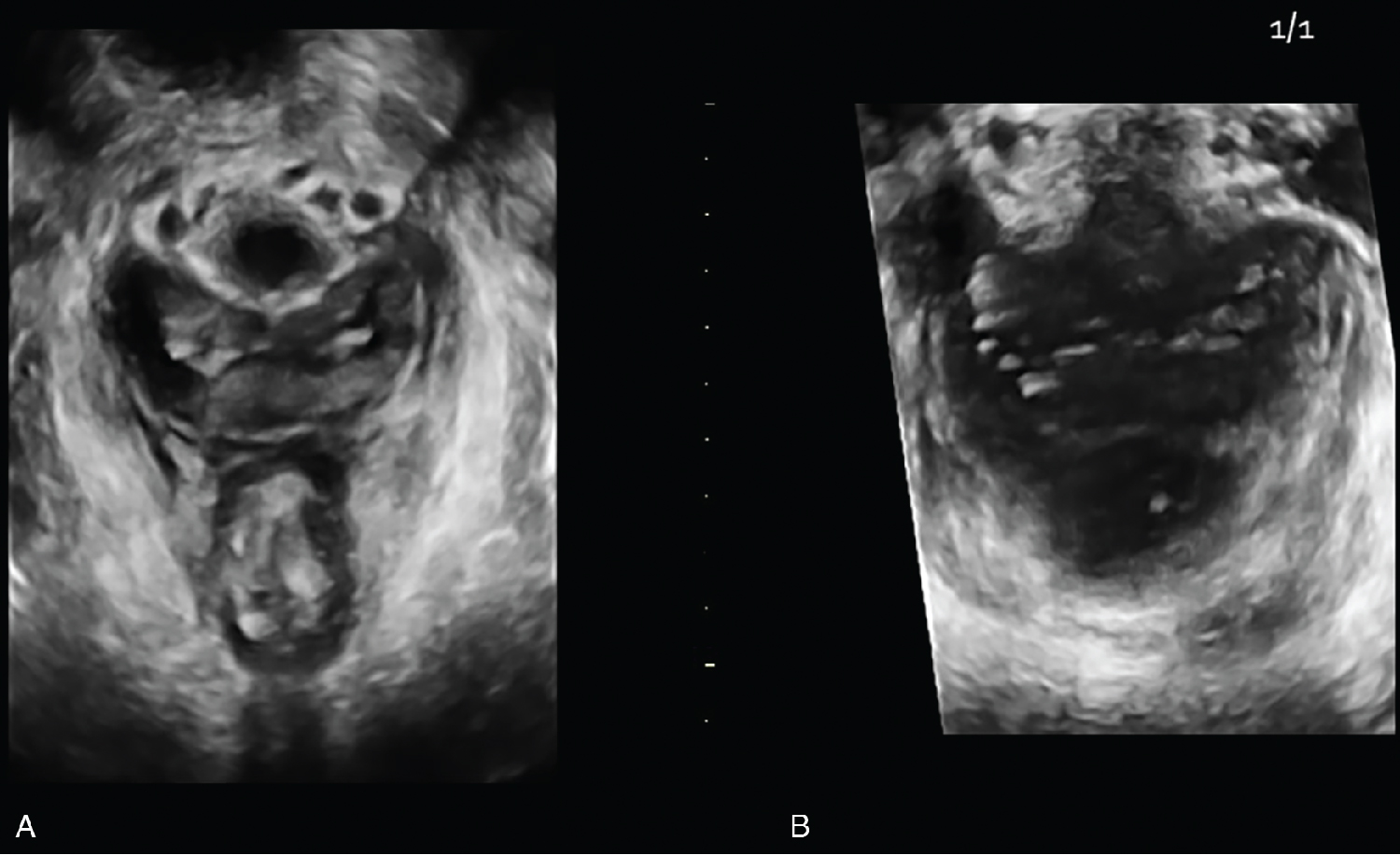
Figs. 244–246 are those of a 45-year-old patient referred for a possible rectovaginal fistula using a 5–9 MHz EV transducer. Which one of the following image findings is not correct?
- a.
The internal anal sphincter (IAS) is disrupted from 11–3 OC.
- b.
There is no measurable IAS at 1 OC and 3 OC.
- c.
There is elevation of the central mucosa toward the defect.
- d.
There is isoechoic tracking noted extending from anterior 12 OC IAS to the patient’s right.
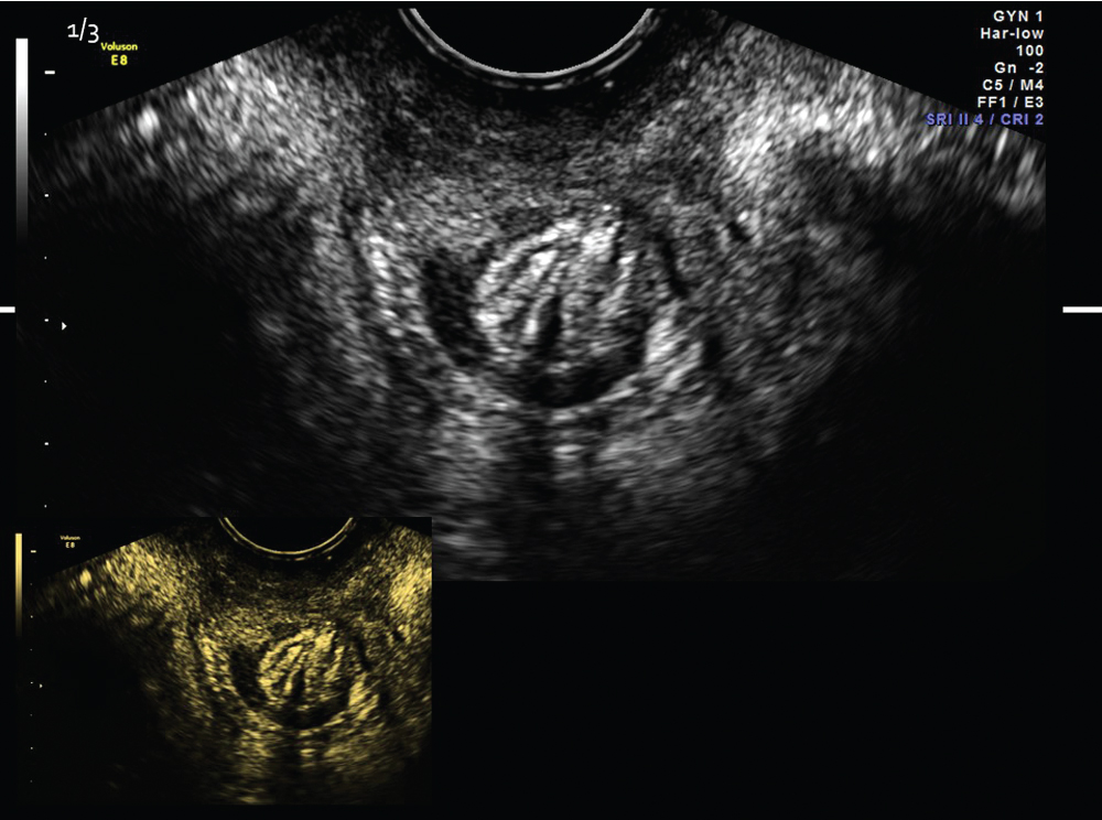
Fig. 244
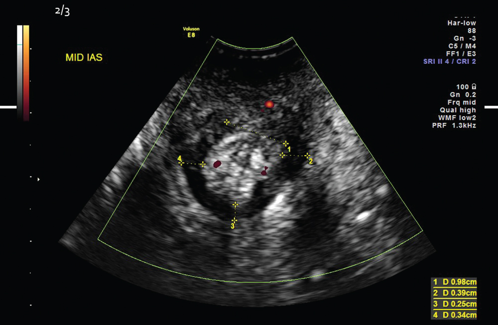
Fig. 245
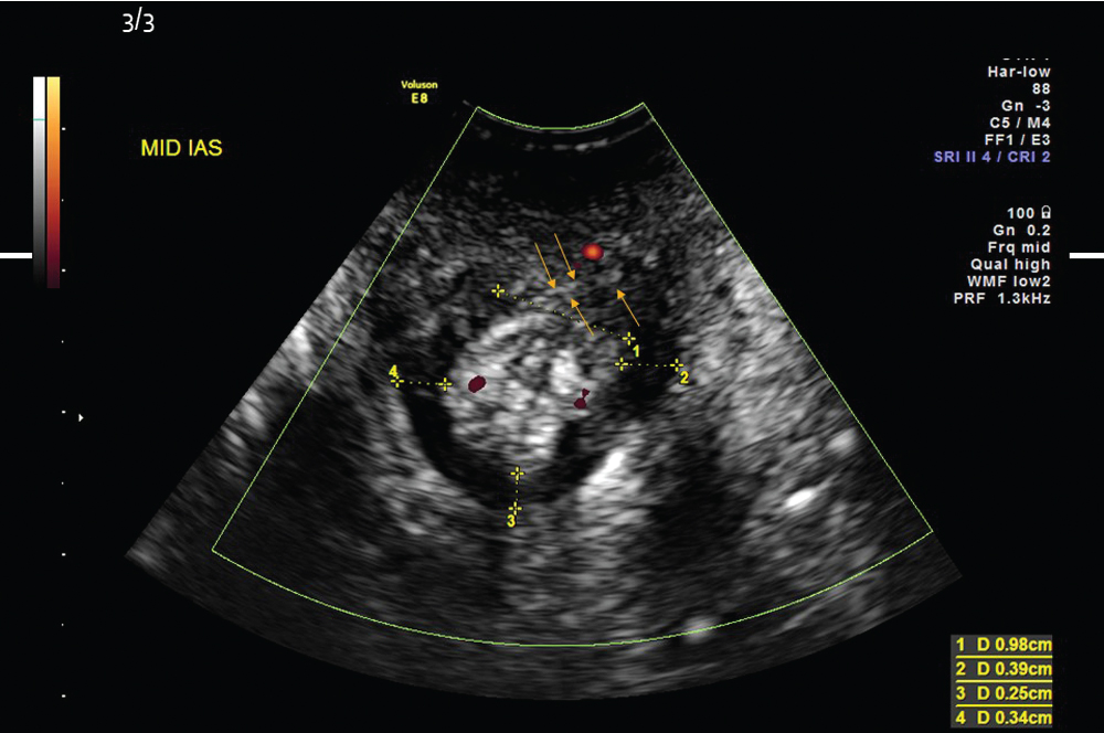
Fig. 246
- a.
- 8.
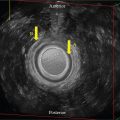
Notice the gold arrows’ distinct thin line appearance along the tracking on Fig. 246 .
Which is the correct diagnosis?
- a.
IAS disruption with no evidence of a rectovaginal fistula
- b.
IAS disruption with concomitant rectovaginal fistula
- a.
Case 115, Figure 247
- 9.
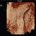
Fig. 247 demonstrates a transperineal 3D volume set, using a 5–9 MHz EV transducer, of the pelvic floor. The A plane is a midsagittal image, the B plane is coronal, and the C plane is transverse of the pelvic floor structures. On what anatomical structure is the center reference point placed as seen on all three orthogonal cuts?
- a.
Anterior vaginal wall
- b.
Anterior rectal wall
- c.
Mid-urethral mucosa
- d.
Posterior vaginal/anterior rectal wall interface
- e.
Posterior rectal wall
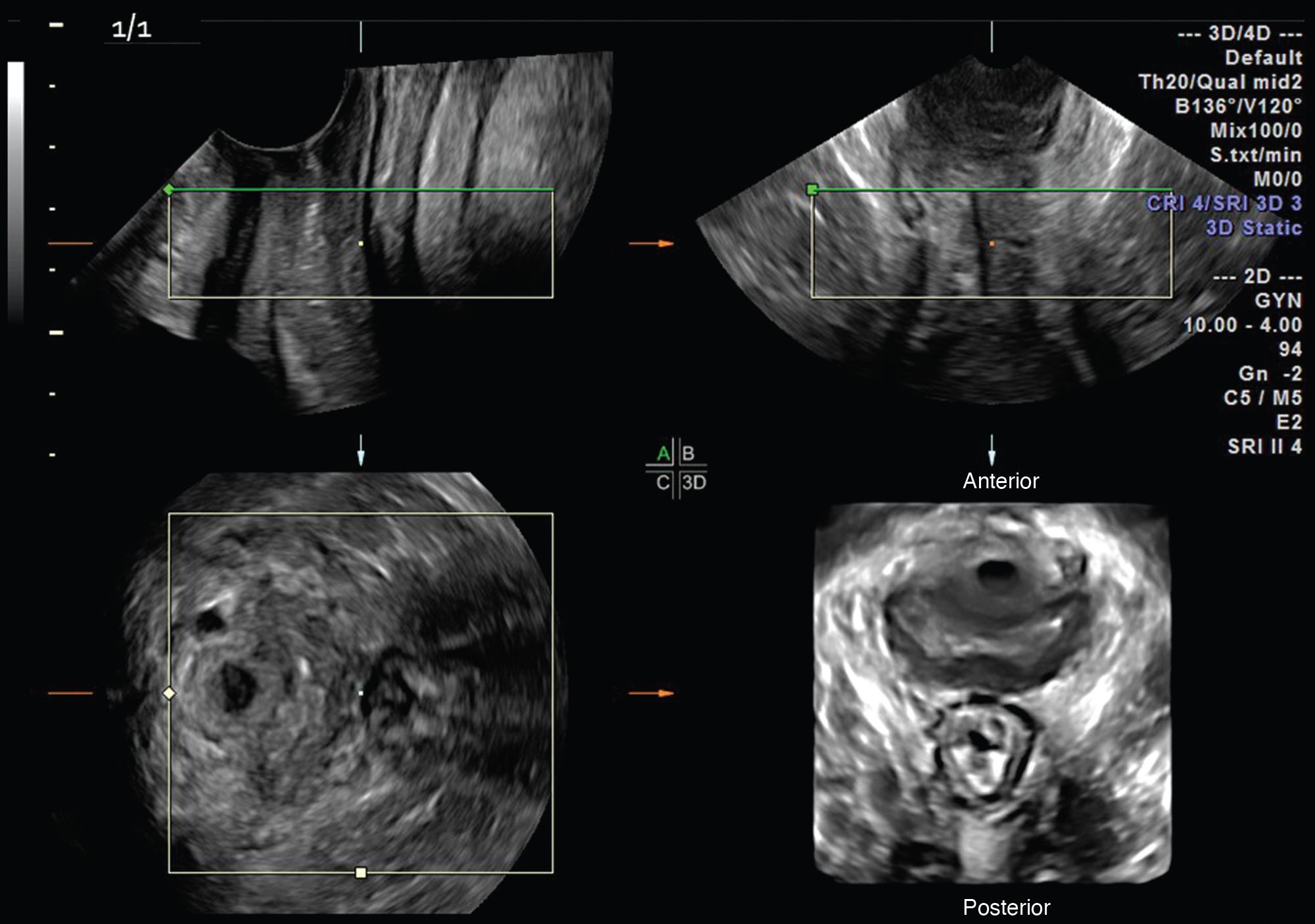
Fig. 247
- a.
- 10.
The 3D rendered image demonstrates a view of the pubovisceralis musculature from anterior (screen top) to posterior (screen bottom) on Fig. 247 .
- a.
Is the vaginal contour symmetric bilaterally? _____
- b.
Is there any evidence of an avulsion? _____
- c.
Is the pubovisceralis muscle complex symmetric bilaterally? _____
- a.
Case 116, Figure 248
- 11.
Which of the images on Fig. 248 demonstrates an avulsion—A or B? ____