Fig. 7.1
MRI images (a) are often reported as axial to the anatomic pelvis, whereas TRUS images (b) are obtained with an end-fire or side-fire transducer, which are from very different planes, often fan shaped (From Kwak et al. [3], with permission)
Multiple fusion platforms are now available commercially. To the authors’ knowledge, no randomized clinical trials offering head-to-head comparisons across these platforms exist at the time of this writing. Further, MRI parameters and the definition of suspicious lesions vary by center, and patient selection biases preclude comparison of approaches across studies. While the workflow begins similarly with image analysis, prostate segmentation, and biopsy planning, the available platforms differ in (1) the image registration algorithm, (2) the method to track the biopsy needle position, (3) the interface to present the ultrasound and MRI images to the operator, (4) additional software capabilities such as mapping and navigation, and (5) the route of biopsy. In this chapter, these aspects are each discussed in general terms before specific fusion platforms are briefly reviewed. This discussion of such a dynamic arena is not intended to be comprehensive, but rather is an introduction to the technologies and techniques of fusion, to give the reader a general sense of the mechanisms and terminologies of the systems, processes, and workflows.
Image Analysis and Planning
After the patient undergoes a multiparametric MRI study, the images are analyzed for suspicious prostatic lesions. Segmentation of the prostate edge is performed, in which the margin of the prostate is defined semiautomatically and verified (and refined where necessary). Biopsy targets are defined as center points or volumes, and approach trajectories may be planned. After these steps, the prostate margin (segmentation volume) and target information are superimposed on anatomic T2W MRI images and transferred to the biopsy workstation for use during the procedure (Fig. 7.2). Although speculative, computer-aided detection platforms may facilitate the automation of this detection strategy, which may eventually prove a helpful assistance tool, given the expertise and subjective interpretation skill sets required for multiparametric image interpretation [5]. Workflow interfaces to PACS and the electronic health record may facilitate future data review in cases of active surveillance (Fig. 7.3).
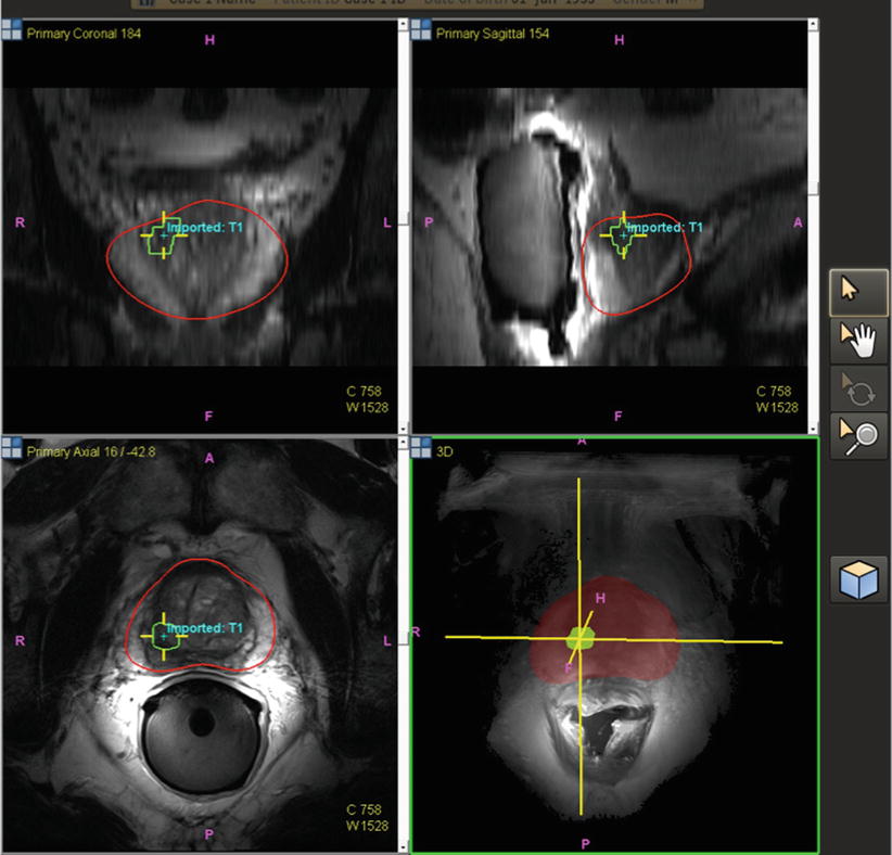
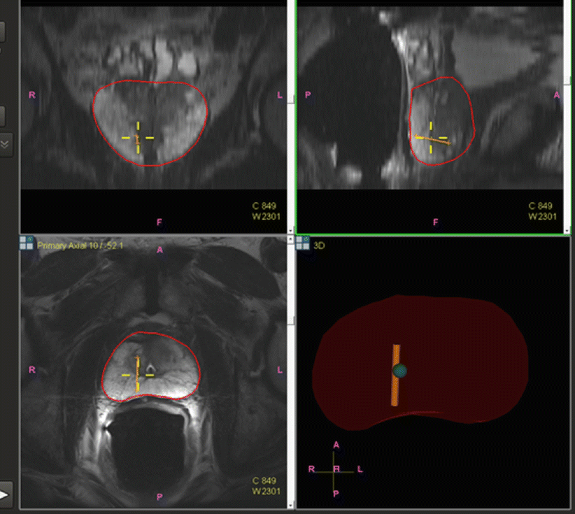
Fig. 7.2
Pre-procedural prostate segmentation on MRI (red line) and MRI target definition (green line) loaded into fusion workstation for registration to TRUS images
Fig. 7.3
Core biopsy location is tracked and mapped (orange line) for the medical record, for later focal ablation or brachytherapy, or for repeat biopsy at a later date as part of an active surveillance program
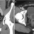
Image Registration
In fusion biopsies, registration is the process of matching MRI to TRUS, thus aligning pre-procedural MRI images (along with segmentation and target information) to a TRUS 3D volume. TRUS volumes may be acquired in 3D or in 2D planes with the volume built by moving the TRUS probe across the prostate from base to apex (a “sweep”). Two software registration algorithms, rigid and elastic, differ in the degree of image distortion allowed for anatomic alignment (Fig. 7.4). Rigid (non-deformable) registration attempts to minimize image distortion by accommodating translation and rotation of images, but not local deformations (Fig. 7.5). While rigid registration maintains the true anatomic shapes and locations, the operator may need to manually adjust the alignment of TRUS and MRI images to account for local registration errors, which may occur from differences in prostate shape between TRUS and MRI images as well as prostate movements induced by pressure from the MRI endocoil or the TRUS probe during imaging [6]. Elastic (deformable) registration, on the other hand, attempts to maximize image alignment by accommodating local deformations in addition to translation and rotation. However, elastic registration may result in distortion of true anatomy to create a “good picture.” On most systems, registration is performed semiautomatically, allowing the operator to fine-tune the alignment of edges and other important landmarks. Both rigid and elastic registration algorithms are available on most fusion systems, permitting the user to judge the most optimal alignment. The operator may toggle between rigid and elastic to determine the most optimal fit. The registration process is often repeated at several steps throughout a procedure, in order to maximize the matching or account for patient or organ motion or deformation. It is important to ensure that high-quality matching remains valid throughout the navigation, as well as mapping biopsy processes.
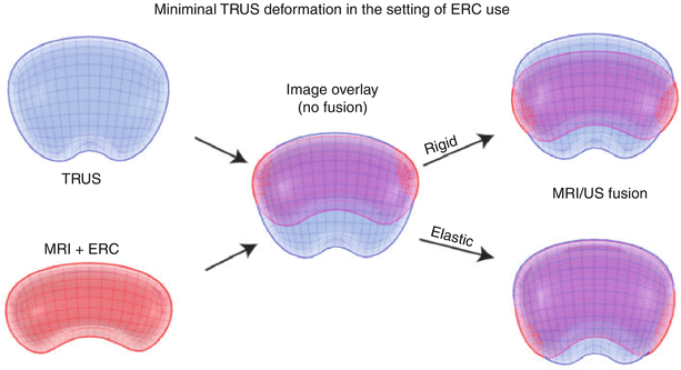
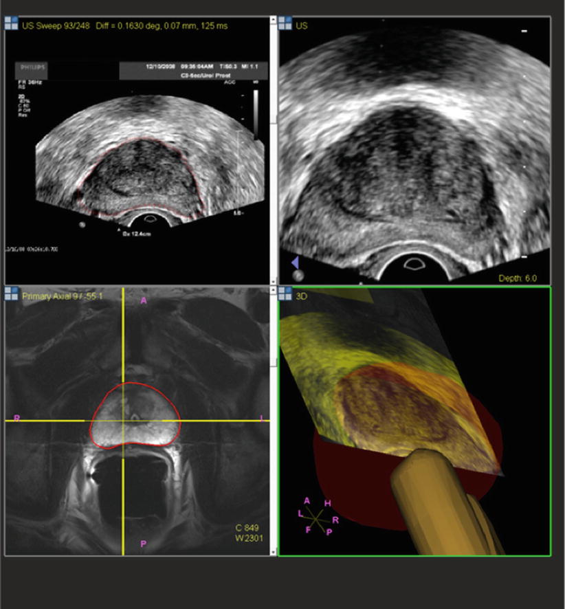
Fig. 7.4
Rigid and elastic registration. Although elastic registration matches the MRI and TRUS images, to make a better combined picture, the operator must be careful so as not to distort the true anatomy too much or move a target to an unrealistic location. Although not obvious, rigid registration with local matching of nearby anatomy and edges may be more accurate than elastic warping (From Logan et al. [6], with permission)
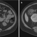
Fig. 7.5
In this case, rigid registration on TRUS and MRI involves similar shapes and may not require elastic registration
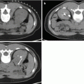
Once MRI and TRUS data are fused, the way in which the resulting images are displayed to the user varies by fusion platform or operator preference. Some platforms overlay the MRI and TRUS images, reformatting the MRI volume to fit to the perspective of the TRUS probe. The standard axial, coronal, and sagittal planes may also be displayed. Other platforms display MRI and TRUS images side by side, either reformatted in the same orientation (Figs. 7.6 and 7.7) or using the tracking information supplied by the biopsy probe to select and display a single MRI slice in axial, coronal, and/or sagittal orientations. Both of these visualization options may be available on some fusion platforms. It is important to define an operator-specific workflow that is both workable and reproducible to maximize accuracy and standardization while maintaining the integrity of the fusion process. This may mean that much of the displayed information is excessive or extra and need not be reviewed from every possible viewpoint during the biopsy.
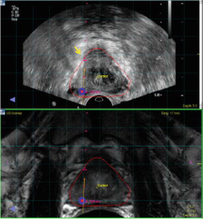
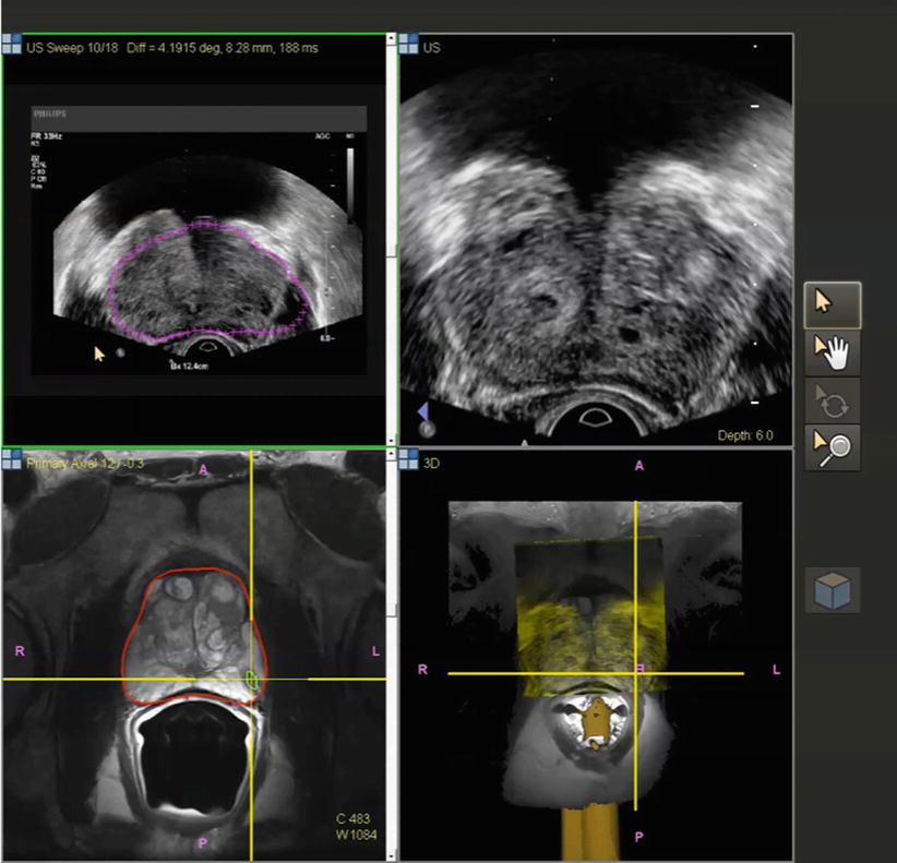
Fig. 7.6
Image co-display on the fusion workstation. Top ultrasound; bottom MRI. Target is displayed on each. Small red dots needle pathway. Red and blue dots target defined on MRI. Needle depth is determined visually by the echogenic white line (arrow) on real-time ultrasound
Fig. 7.7
Co-display of registered TRUS (top) and MRI (bottom) images after building a 3D volume on TRUS. Different shapes of prostate segmentation (purple and red lines) can be corrected by elastic registration and fusion
Tracking Approaches
In addition to the registration of MRI and TRUS images, fusion platforms may track and record the position of the biopsy probe in 3D space. This information may be used to present the relevant slices of the imaging data or be used for mapping and navigation (see below). There are three basic methods to attain MRI-TRUS fusion, which vary in their technologies, strengths, weaknesses, and initial intent of design. These are (1) electromagnetic tracking (“medical GPS”), (2) position-encoded joints in smart robotic arms, and (3) image-based tracking.
Some platforms (such as UroNav, Invivo; Virtual Navigator, Esaote; and Real-time Virtual Sonography, Hitachi) employ passive electromagnetic tracking, often dubbed “medical GPS,” in which the position of a small sensor (“car”) attached to the biopsy probe is detected by a magnetic field generator (“satellite”) fixed to the operating table on an arm and external to the patient. Such tracking takes advantage of the Faraday principle or the fact that a coil (sensor) in the presence of different and changing magnetic fields (field generator) elicits an electrical current related to the different magnetic fields turned on sequentially by the field generator. The computer then converts this changing electrical current into a 3D position in space, in relation to the fused image which shares the X-Y-Z 3D Cartesian coordinates. Electromagnetic tracking preserves the conventional freehand biopsy approach, resulting in a relatively shallow learning curve [7, 8]. During the biopsy procedure, the operator typically performs an initial TRUS “sweep” of the prostate, after which the 3D ultrasound data are registered to the pre-procedural MRI data. Subsequently, the 3D position of the TRUS probe is used to guide the operator toward the planned approach trajectory (angle and position) for each suspicious lesion to be sampled (see “Mapping and Navigation” below) as well as to document the location of each biopsy core taken.
“Robotic” fusion platforms such as Artemis (Eigen), BiopSee (Pi Medical), and BioJet (BK Ultrasound) directly control the biopsy probe’s angle and position. The biopsy probe is mounted on a mechanical stepper with position sensors or a more sophisticated articulating robotic arm that contains angle-sensing encoders. When the operator drives the robotic arm during the procedure, the angle and position are automatically calculated based upon the encoded joints. While the robotic aspect may add to the learning curve of this fusion platform, high accuracy in positional tracking may be achieved.
A third approach employs image-based software tracking methods, as exemplified by the Urostation (Koelis) platform that relies on retrospective TRUS-TRUS registration. Instead of utilizing real-time targeting, a 3D TRUS image acquired after each biopsy is registered with an initial 3D TRUS sweep to confirm the needle position [8]. In this manner, position tracking is achieved without the use of additional hardware such as electromagnetic generators or robotic arms. In addition, since the freehand biopsy approach is preserved, these image-based systems tend to most resemble the conventional TRUS technique, in terms of operator input. Initially designed for location mapping and recording, these systems may be modified and used for prospective navigation and guidance as well, with some potential limitations, such as performing a 3D TRUS volume after every needle, with the needle held in place during TRUS imaging.
Mapping and Navigation
To further help the biopsy operator, fusion systems offer varying degrees of mapping and navigation (or guidance) capabilities. Mapping refers to the process of tracking the imaging location of a biopsy specimen and referencing it to pre-procedural MRI for later use. Mapping is done in order to better locate repeat biopsies in the setting of active surveillance of low-grade cancers (Fig. 7.3). Navigation (or guidance) refers to the platform’s ability to aid prospective placement of a biopsy needle toward a target that was pre-identified on MRI but now targeted with TRUS, with the needle being directed transrectally and/or transperineally, depending on the platform. Mapping may be more important for blind or sextant biopsies that are positive, since the exact location may not otherwise be known or tracked, other than to say it was from the “left base,” for example.
Route of Biopsy
Prostate biopsies can be performed transrectally or transperineally, with the former being the more commonly used technique. Given that the biopsy needle passes through the rectal mucosa in the transrectal approach, infection and sepsis following transrectal biopsy have been a concern. Recently, increasing rates of sepsis arising from transrectal biopsy have been reported, perhaps in part related to increasing prevalence of colonization with resistant organisms [9, 10]. A retrospective study of almost 5900 Japanese patients who underwent transrectal and/or transperineal biopsies found no statistically significant difference in the overall rate of genitourinary tract infections between the transrectal (0.83 %) and the transperineal route (0.57 %), although the rate of febrile (≥38 °C) infections occurred more frequently after transrectal (0.71 %) than transperineal (0.16 %) biopsies (P = 0.04) [11]. A prospective study of 245 transperineal biopsies performed at several centers in Melbourne, Australia, resulted in zero hospital readmissions for infection after transperineal biopsy [12]. These rates may be heavily impacted by local factors such as frequency of resistance to common prophylactic antibiotics. Consulting with a local infectious disease expert may be prudent to help develop local prophylactic standard procedures.
Major Platforms
Before exploring the technology, workflow, and strengths of each commercially available fusion platform, it is important to note that many platforms have evolved over time. Some were initially developed with one purpose (mapping or navigation) but have subsequently added the other capability. Likewise, some systems were initially developed with only rigid or elastic registration, or only the transrectal or transperineal approach, and have added the counterpart options more recently. Therefore, much of the data and characteristics of these systems in published literature likely represents one moment in time and may have evolved since publication. Further, the authors are most familiar with the UroNav system, having helped to develop that system over the past >12 years.
Electromagnetic Tracking
The UroNav


Related posts:
Stay updated, free articles. Join our Telegram channel
Full access? Get Clinical Tree
