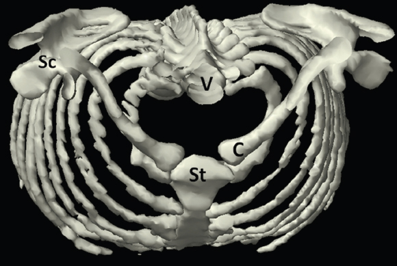
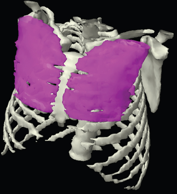
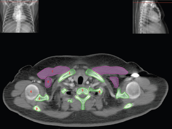
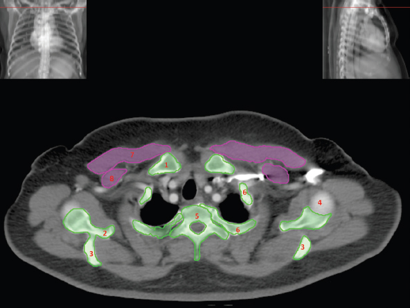
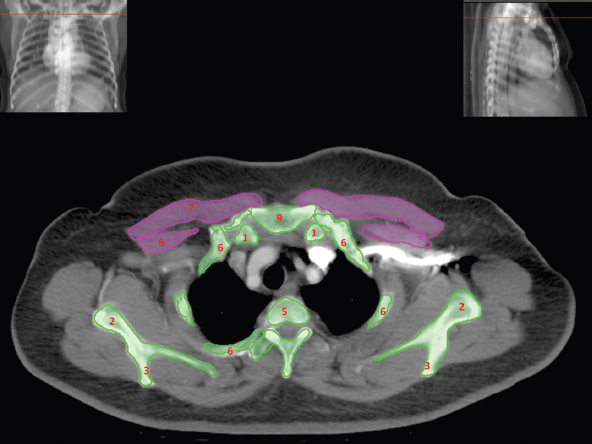
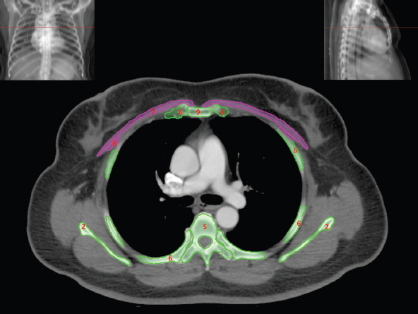
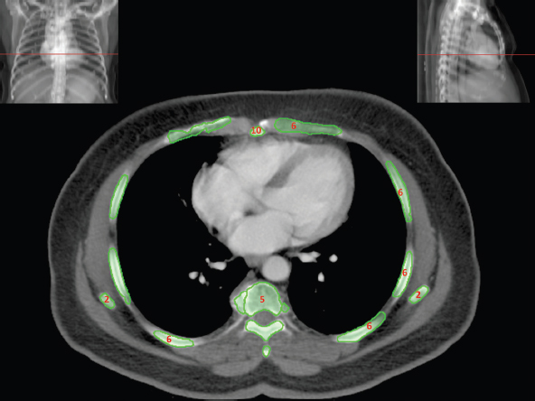
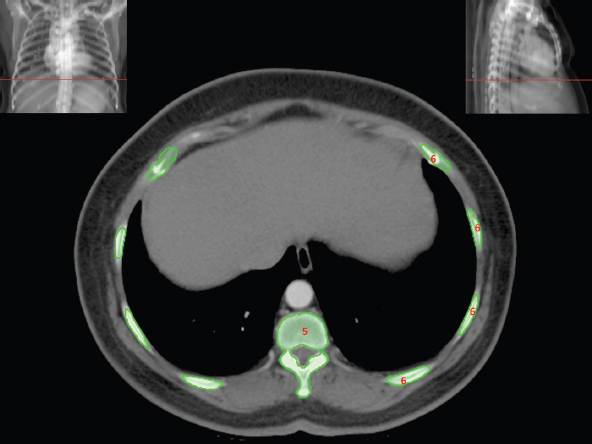
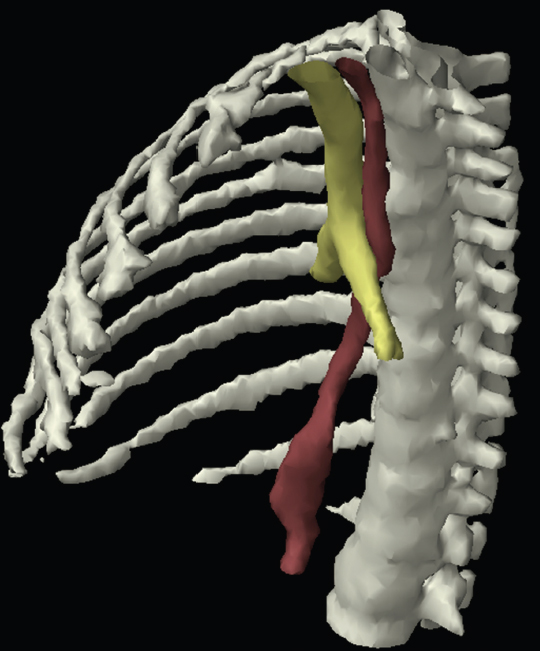
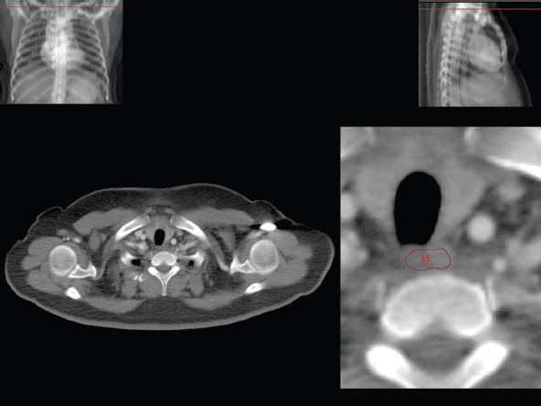
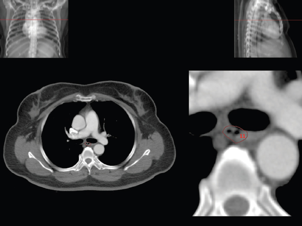
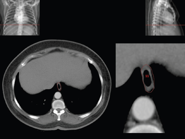
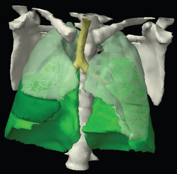
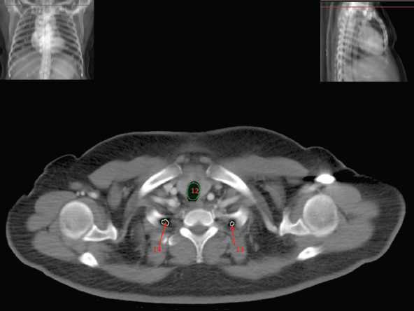
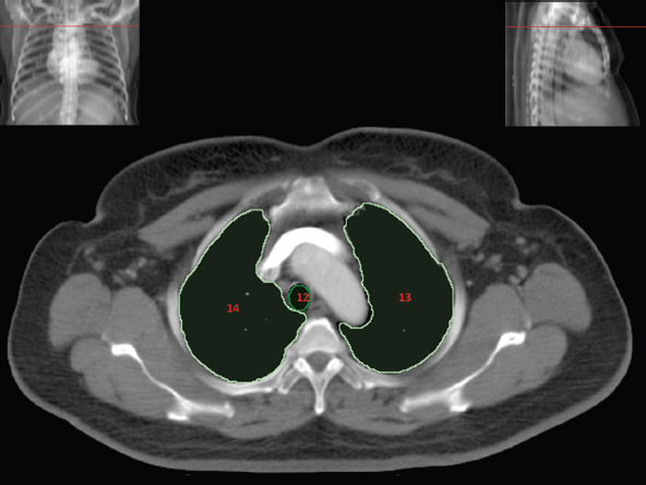
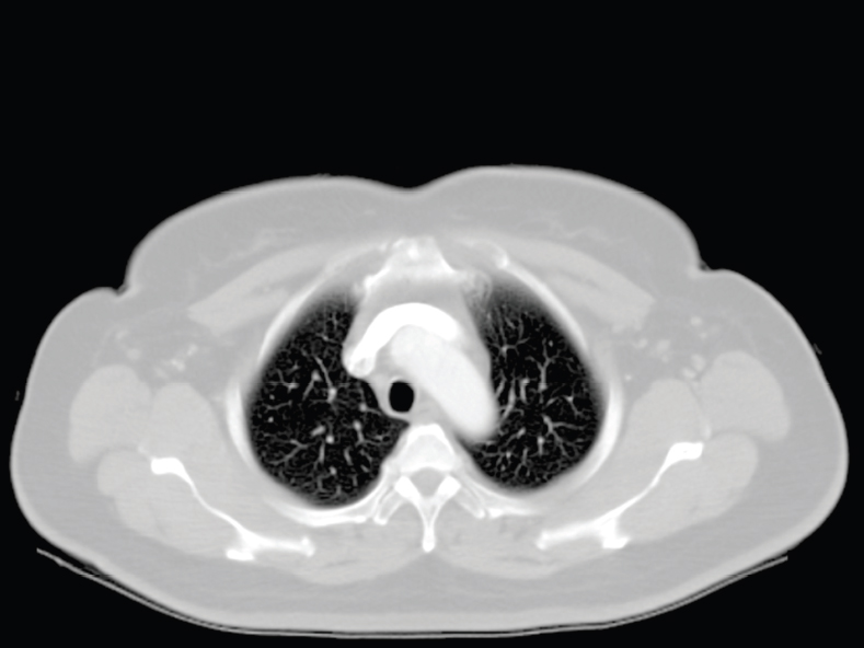
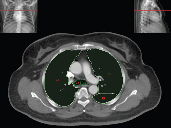
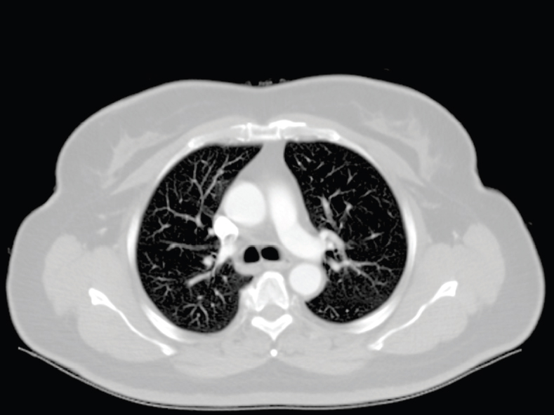
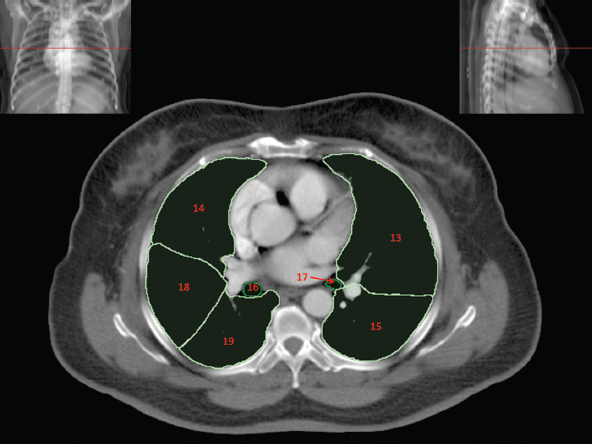
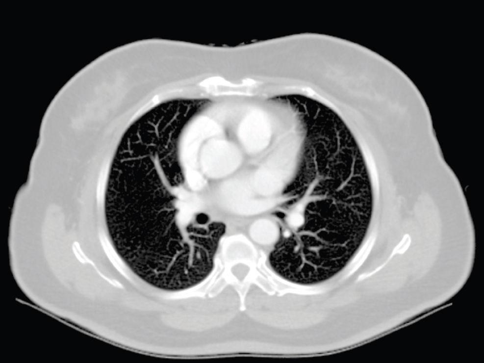
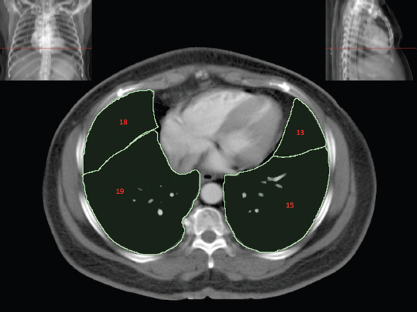
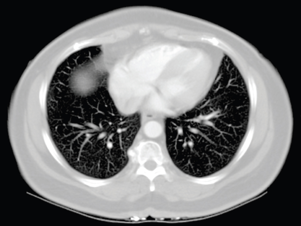
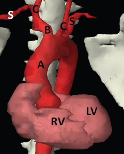
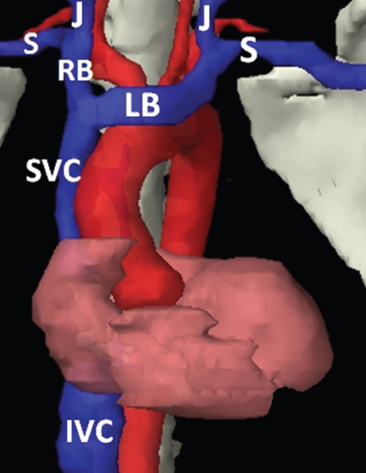
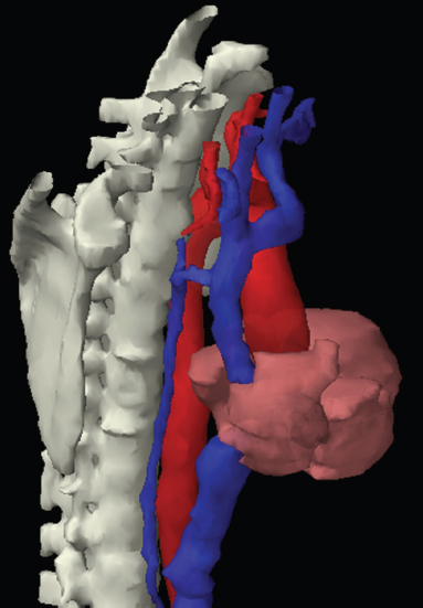
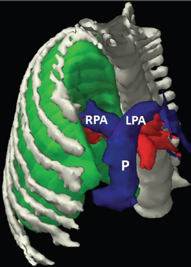
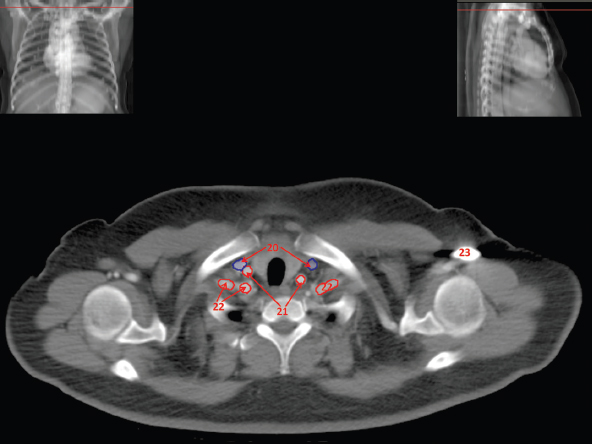
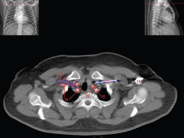
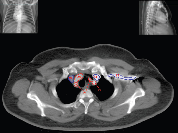
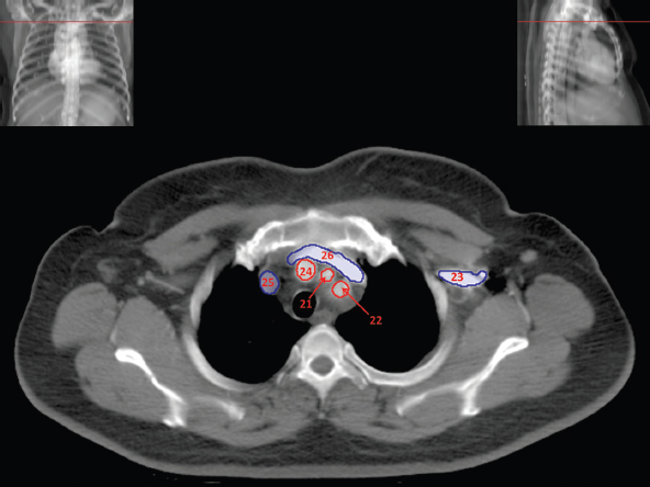
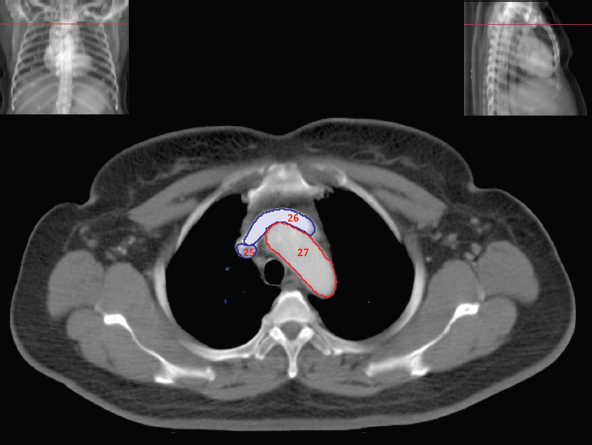
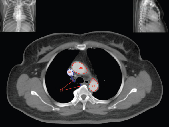
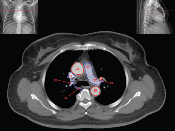
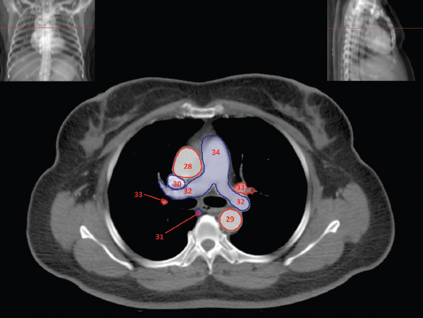
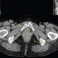
The skeletal system in the thorax is designed to produce a resizable framework within which the lungs can expand and contract while retaining protection. The thoracic cage is sealed interiorly by the muscular sheet of the diaphragm. The superior aspect of the cage is relatively small and bounded by the highly curved upper ribs and the clavicles (C) joining the sternum (St) as seen in Figure 3.1.1. Additional support is provided by the vertebral column (V) posteriorly and the scapula (Sc) supero-posteriorly. Anteriorly, the sternum protects the thorax. The superior of the sternum forms the suprasternal notch with the heads of the clavicles. Interiorly, the sternum tapers to a point known as the xiphoid process, or xiphisternum. On CT, the bony detail is not of major interest but the difference between thoracic and lumbar vertebrae should be noted, in particular the facets for attachment of the ribs. Figure 3.1.1 Figure 3.1.2 Although there are many thoracic muscles, for radiotherapy purposes these are of little direct interest. The pectoralis muscles, however, should be identified in order to help determine the posterior border of the breast tissue and some lymph node groups. Figure 3.1.2 shows how the pectoralis major muscles cover the superior portion of the chest, connecting the sternum and clavicle with the greater tubercle of the humerus. Underneath this lies the smaller pectoralis minor muscle that connects the third, fourth and fifth ribs to the scapula. The other muscle of note in the thorax is the diaphragm. This domed muscle flattens when tensed to expand the thorax. It can be seen on lower thorax CT scans as a thin sheet separating the lungs from the abdominal contents. It is particularly thick at the medial and posterior region near the vertebrae. It is attached to the vertebral column by two crura (one per side). These have already been identified in Chapter 2. Figure 3.1.3 Figure 3.1.4 Figure 3.1.5 Figures 3.1.3 to 3.1.5 show the superior of the thoracic cage formed by the clavicle (1), scapula (2) and upper thoracic ribs (6). In Figure 3.1.3, at about T1, the superior spine of scapula (3) can be seen posteriorly. Laterally to the scapula can be seen the head of humerus (4). Anteriorly lie the pectoralis muscle group (7 and 8). Symmetry of these muscles is dependent upon the choice of immobilisation position adopted. If both arms are raised above the head, the lateral bulk of both pectoralis muscles will be extended and stretched superiorly and will be symmetrical; however muscle bulk appearances will differ if one arm is raised and the other remains at rest by the patient’s torso. Each pectoralis major muscle (7) spans a relatively large proportion of the upper thorax. These paired fan-shaped muscles cross the superior anterior chest wall from the sternum (9) and inferior clavicles (1) to the greater tubercle of each humerus (4). Demarcation between the pectoralis major (7) and pectoralis minor (8) is aided by a fat plane between them. Level II interpectoral lymph nodes (Rotter’s) may be present within this fat plane and can reduce interpectoral fat plane perception, but any resulting asymmetry will be apparent when both sides are compared. The pectoralis minor muscles are the smaller of the two groups as their name suggests. They lie inferior to pectoralis major and slightly laterally and span the gap from the third, fourth and fifth ribs to the coracoid process of each scapula. The fat border between the muscle and deep breast fibroglandular tissue is discernable in Figure 3.1.6. Although superior demarcation of local invasion of underlying musculature is best demonstrated by contrast and fat suppression MRI imaging, the fat plane between the breast glandular tissue and pectoralis major muscle can be clearly seen at this level. Figure 3.1.6 Figure 3.1.7 In Figure 3.1.6, the scapulae have a particularly thin cross-section. As both arms are raised above the patient’s head the scapulae rotate and appear to extend slightly laterally. The normal bony thoracic skeleton will have smooth contours and be symmetrical, providing both arms are either positioned above the head, or down by the torso. Like all skeletal bones there is a high natural contrast between the soft tissue and sternum (9), ribs (6) and spine (5). There are also often calcification deposits present within the costal cartilages, particularly close to the sternum (9). Figure 3.1.7 illustrates the inferior aspects of the scapulae (2) and the xiphisternum (10) at the inferior of the sternum. Figure 3.1.8 Figure 3.1.8, at T11 level, demonstrates the junction between the thoracic and abdominal spaces, which are separated by the diaphragm. The diaphragm is a thin domed sheet of muscle, and should be of regular width with no contour abnormalities. It can be difficult to visualise due to its relatively thin nature and proximity to abdominal soft tissue structures. This is simplified by adjacent intra-abdominal fat deposits, although these may not be apparent above the liver on the right hemi-diaphragm. Cordlike thickening of the paravertebral muscle fibres is sometimes visualised on forced inspiration and crura can be clearly visualised on lower images. Retrocrural evaluation is vital for determining the presence of lymphadenopathy. The spine should be viewed on bony window settings to assess for metastatic deposits. These are frequently involved in destructive processes in the laminae and vertebral bodies (5). Solitary fractures at atypical locations, such as upper and mid thoracic regions, should be treated as suspicious of metastatic disease. The spinal canal should also be examined for soft tissue extension into the canal and cord. After the complexity and diversity of the digestive system in the abdomen and pelvis, the reader will be relieved by the simplicity of the thoracic digestive system. This comprises the thin collapsible muscular tube of the oesophagus. The small cross-section, frequent lack of lumen and absence of surrounding fat often make the oesophagus hard to spot on CT, despite it being a relatively common treatment site. The oesophagus tends to be divided into three distinct sections: an upper, middle and lower third. The cervical section starts at the lower posterior hypopharynx, becomes the thoracic oesophagus to drop through the mediastinum and pierces the diaphragm as the abdominal oesophagus to join the stomach. It can be located for much of its upper course by an understanding of its position posterior to the trachea. In Figure 3.2.1 the brown oesophagus hugs the posterior border of the green trachea. Below the bifurcation, it descends in roughly the same position, moving slightly left and anteriorly towards the stomach before penetrating the diaphragm through the oesophageal hiatus at about T10. Figure 3.2.1 Figure 3.2.2 The upper thoracic oesophagus (11) extends from the level of the suprasternal notch to the tracheal bifurcation as seen in Figure 3.2.2. The upper oesophagus can be difficult to visualise on non-contrast CT by the inexperienced viewer due to the relatively small cross-section and irregular shape. Occasional lack of clear surrounding fat and incomplete distension also further complicate clear demarcation. Localisation can be aided by considering a few simple guidelines. Normally the oesophagus is located in the midline, although lateral displacement is possible. The usual position is posterior to the flat portion of the trachea and anterior to the thoracic vertebral bodies as seen in the enlarged Figure 3.2.2. Figure 3.2.3 Figure 3.2.4 The wall thickness should be relatively uniform along its length. Areas of thickening of more than 3-5mm and prestenotic dilation are indicative of disease. Intraluminal air or well timed administration of intraluminal CT contrast can help visualisation of the lumen and wall thickening. This patient’s lumen can clearly be seen in the enlarged Figures 3.2.3 and 3.2.4. IV contrast agent will help delineate adjacent vascular structures and the oesophagus will be seen in between the azygos vein and aorta. The mid-thoracic portion behind the heart is very close to the left atrium, and can sometimes be poorly visualised due to cardiac motion. Inferior to this level, the path of the oesophagus moves anterior until it reaches the diaphragm. The inferior portion of the oesophagus continues beyond the oesophageal hiatus in the diaphragm until it joins the gastric fundus. The respiratory system comprises most of the bulk of structures within the thoracic cage and is designed to enable gaseous exchange by expanding to draw in fresh air and then contracting to expel used air. The inlet for the air is the trachea which has a horseshoe-shaped appearance in cross-section. The trachea is held open by almost complete rings of cartilage. The rings are open at the posterior of the trachea, causing a flattened posterior wall and the characteristic shape on CT This structure allows for passage of food through the adjacent oesophagus without the rings impeding its progress. The trachea splits into two bronchi and these then conduct the air to the paired lungs. The left bronchus supplies a reduced volume of inferior lung tissue due to the position of the heart so tends to take a more horizontal approach than the right bronchus. On CT, this manifests itself by a more oval cross-section than the circular appearance of the right bronchus. The lungs themselves are spongy in nature and thus differ from the air tubes, which are hollow air-filled structures. This difference is apparent when ‘lung’ window settings are used. On ‘soft tissue’ settings, both lung and air tubes appear black. As previously mentioned, the heart occludes much of the left side of the thorax and this means that the lungs are asymmetrical in structure and size. The left lung has an upper and lower lobe whereas the right has an upper, lower and middle lobe. These terms are somewhat misleading as Figure 3.3.1 demonstrates. The anterior of the upper lobes (light green) can be seen to extend to the inferior part of the thorax. Additionally, the posterior upper lobes (mid green) extend superiorly almost to the lung apices. This can cause confusion if a lower lobe tumour is reported yet appears to be in the superior part of the thoracic cage. The lobes are separated by fissures. These fissures are occasionally visible on CT, but are also identifiable by the relative paucity of vessels within the lung at the edges of the lobes. On the medial aspect of each lung can be found the hilum, where the various tubes, such as the bronchi, nerves and pulmonary vessels, enter and leave the lungs. Figure 3.3.1 Figure 3.3.2 At the level of the sternal notch the most visible part of the respiratory system is the trachea (12). This structure is easily recognisable on CT by its distinctive horseshoe appearance. It contains air with HU of -1000 and is black in appearance on all window width and level settings as seen in Figure 3.3.3. At this level the trachea is partially enclosed by the thyroid gland lobes (laterally) and isthmus (anteriorly). The tracheal cartilages may also contain calcified deposits in some patients. The tips of the lung apices are also just visible here (13 and 14). Figure 3.3.3 Figure 3.3.4 Within the superior mediastinum, Figures 3.3.4 and 3.3.5 show that the trachea (12) varies considerably in cross-sectional shape, and is not always midline. Here it deviates slightly to the right due to the location of the aortic arch. Here, the trachea has a rounded cross-section, but is still easily identifiable as it contains air. The borders of the lung segments are not easily discerned without in-depth knowledge of bronchopulmonary segments. Apical zones of upper lobes of both lungs (13 and 14) are also visible; both are well aerated and are adjacent to the chest walls. The difference in density between air in the trachea and lung tissue can be noted on Figure 3.3.5. Figure 3.3.5 Figure 3.3.6 Still within the superior mediastinum, at T4/5, the trachea has bifurcated into the right (16) and left (17) main bronchi. Both are air-containing structures anterior to the vertebral body, and slightly to the right of centre. The fissures dividing the lungs into lobes can sometimes be seen on thin slices through the lung. Anterior segments of lower lobes of right (14) and left (13) lungs as well as superior segment of left lung (15) are seen. Figure 3.3.7 shows how the pulmonary vessels and bronchi separate further and reduce in size and accompany each other to the periphery. This is termed the bronchial tree. Figure 3.3.7 Figure 3.3.8 In Figures 3.3.8 and 3.3.9, the two main bronchi have further subdivided into the right lower lobe bronchus (16) and left lower lobe bronchus (17). Using lung window settings, it is possible to visualise individual lobes within the lungs as seen on the left in Figure 3.3.9. Lobar segmentation is more complex and might not be apparent on slices thicker than 5mm but may be visualised by following branches of the pulmonary veins. The right lower lobe (19), middle lobe (18) and upper lobe (14) are easily identified. The left lower lobe (15) and upper lobe (13) can also be seen. Figure 3.3.9 Figure 3.3.10 Figures 3.3.10 and 3.3.11 show the middle (18) and lower (19) lobes of the right lung as well as the upper (13) and lower (15) lobes of the left lung. As the pulmonary vessels and branches of the bronchial tree extend deeper into the lungs, they become too small to visualise on soft tissue settings, although they are visible in Figure 3.3.11 due to their high inherent contrast. An osteophyte on the vertebral body is slightly displacing the medial aspect of the lower lobe of the right lung. These osteophytes are normally due to degenerative spondylosis and are often seen on the lateral and anterior aspects of the thoracic vertebral bodies. Figure 3.3.11 Figure 3.4.1 Although some aspects of the cardiovascular system represent a challenge to CT interpretation, it is rare that the therapy radiographer is required to identify specific elements of it. An understanding of the location of the main vessels and structures will, however, enable abnormalities to be spotted, lymph node regions to be identified and assist with general orientation. The heart operates as a fluid pump with two main pumping chambers (the ventricles) and 2 ante-chambers (the atria) that collect blood for pumping. Figure 3.4.1 illustrates the main exit route of blood from the heart. Blood exits the left ventricle (LV) to the main arteries via the ascending aorta (A). This arches superiorly and posteriorly before descending slightly anteriorly and to the left of the vertebral column. The first few branches off the aorta are of some interest. The very first are the tiny coronary arteries that supply the heart muscle itself. These are of considerable interest in radiotherapy as they are increasingly thought to be dose limiting structures associated with cardiac morbidity. Identification of these is addressed in the Structure Focus section (3.5). After the coronary artery branches is the brachiocephalic artery (B). This is an unpaired artery that is necessary due to the left-hand position of the heart and carries blood to the right-hand side of the thorax. It then branches into the right subclavian (S) and common carotid (C) arteries. The subclavian arteries duck under the clavicles to supply the arms while the carotids ascend to supply the head and neck. Figure 3.4.2 The left common carotid (C) and subclavian (S) arteries are the next two main arteries emerging directly from the aorta and do not require a brachiocephalic artery to link them to it. After the arch, the aorta plunges interiorly with only a few branches emerging from it, such as the bronchial arteries that supply the lungs with oxygenated blood. Most of the major arterial branching occurs after the aorta has penetrated the diaphragm, as seen in the previous chapter. The deoxygenated blood from the body returns via the venous system to either the superior or inferior vena cava. The superior vena cava (‘SVC’) returns blood from the head and neck and is fed by left and right brachiocephalic veins. Unlike the corresponding arterial supply, these are paired structures and are in turn supplied by the jugular and subclavian veins. Figure 3.4.2 shows the jugular (J) and subclavian (S) veins on each side joining to form the right and left brachiocephalic veins (RB and LB). These then combine to form the relatively short SVC. The IVC collects most of the blood from the lower body and can be seen slightly anterior and to the right of the aorta as it rises through the thorax. Some blood is also returned via the smaller azygos and hemi-azygos veins which run anteriorly to the vertebral column and connect the superior and inferior vena cavae. Figure 3.4.3 The veins all empty into the right atrium as seen in Figures 3.4.2 (anterior view) and 3.4.3 (lateral view). The azygos vein can be seen clearly in Figure 3.4.3 as the smaller vein posterior to the vena cavae and aorta. Figure 3.4.4 The right atrium pumps the deoxygenated blood into the right ventricle and blood passes from here into the pulmonary trunk. This is a short vessel that runs posteriorly before splitting into the left and right main pulmonary arteries. Figure 3.4.4 illustrates the pulmonary trunk (P) emerging from the right ventricle at the anterior of the body, passing posteriorly and then bifurcating into the left and right pulmonary arteries (LPA and RPA). After penetrating the lungs at the hilum, the pulmonary arteries branch dramatically to perfuse the lungs. After gaseous exchange has occurred, the oxygenated blood is gathered into the four pulmonary veins. Each lobe has a corresponding pulmonary vein apart from the right middle and upper lobes, which both drain into a single vein. The pulmonary veins leave the hilum and empty into the left atrium. They can be seen on CT interiorly to the pulmonary arteries and posteriorly to the atria. From the left atrium, the oxygenated blood is pumped to the left ventricle ready for the circulatory cycle to begin again. Figure 3.4.5 At the thoracic inlet several vessels can be visualised, especially with the aid of IV contrast agent. Depending upon the timing of the injection and scan acquisition, the opacity of the different vessels can vary. This area is conventionally scanned 25-30 seconds from the start of injection, typically injected at 3mls/second. This allows the IV contrast to circulate and mix through the cardiopulmonary system, and enter the aorta. Figure 3.4.5 shows some contrast still entering the system via the subclavian vein (23). This is quite dense as it has not yet mixed and become more diluted with blood within the cardiopulmonary system. In Figure 3.4.5, lateral to the trachea, lie the common carotid arteries (21), medial and posterior to the internal jugular veins (20). Asymmetry of jugular veins is relatively common, and as such has very little pathological significance. The subclavian arteries (22) can be seen extending towards each axilla. Figure 3.4.6 Figure 3.4.6 demonstrates both subclavian arteries (22). On the right can also be seen the subclavian vein (23). Both common carotid arteries (21) are visible lateral to the trachea. Behind the head of the clavicle is the right internal jugular vein (20) adjacent to the right common carotid artery and subclavian vein. Figure 3.4.7 Slightly more interiorly in Figure 3.4.7, the jugular and subclavian veins have converged into the right (25) and left (23) brachiocephalic veins. The effect of contrast within the left brachiocephalic vein can be noted when compared with the appearance of the right vein. Paired subclavian veins and arteries can be seen in longitudinal section posterior to the pectoralis minor, although the high level of contrast on the left (23) obscures details. These vessels are usually easily identified due to the surrounding axillary fatty tissue. Figure 3.4.8 At this level (T2/T3) the left subclavian vein (23) is still visible, posterior to the left pectoralis minor. Within the superior mediastinum, the vessels are fewer and more easily distinguished. There are three main arteries here, and two main veins. There is just one brachiocephalic artery (24). This is the first main vessel arising from the arch of the aorta. The next major branch is the left common carotid artery (21) and then the left subclavian artery (22). The two brachiocephalic veins appear slightly different at this level, as the longer left vein (26) extends across the mediastinum towards the right vein (25). They will meet interiorly to form the SVC. Figure 3.4.9 In Figure 3.4.9 the arch of aorta (27) is visible curving posteriorly and laterally within the mediastinum. Figure 3.4.10 The left brachiocephalic vein (26) can be seen extending around the anterior aspect of the arch of aorta and converging with the right brachiocephalic vein (25) in order to form the SVC (30 in Figure 3.4.10). The trachea and oesophagus can be seen medial to the aortic arch. Figure 3.4.10 is at a level just inferior to the aortic arch (about T4/T5) so both the ascending (28) and descending (29) thoracic aorta can be identified. The SVC (30) is lateral to the ascending aorta, and is relatively radio-opaque due to a higher concentration of contrast. The aorta usually has a diameter less than 4cm. Any increase could suggest aneurysm, infiltration or adjacent disease processes. The azygos vein (31) is arching over the root of the right lung, adjacent to the trachea. The azygos vein, if particularly bulky, can sometimes be mistaken for para-aortic lymph nodes. Figure 3.4.11 Medial to the ascending aorta (28), the main pulmonary trunk (34) arises and passes posteriorly. It then bifurcates and in Figure 3.4.11 the left main pulmonary artery (32) extends into the hilum of the left lung. Just anterior to this are smaller pulmonary vessels (33). Slightly inferior, in Figure 3.4.12, a further subdivision of a right pulmonary vein (33) can be seen. The descending thoracic aorta (29) is clearly visible on both these images posterior to the left main pulmonary artery. Between the ascending aorta (28) and bifurcation of trachea (carina) is the ‘aortopulmonary window’ which contains mediastinal lymph nodes. Any diseased lymph nodes may also be seen inferior to the carina and visualisation of these is made easier by the presence of mediastinal fat. The SVC (30) can be seen adjacent to the ascending aorta (28). It is much smaller than the aorta since it only contains blood from tissue superior to the heart. Although veins are composed of the same three layers as arteries, the walls are much thinner, lack the internal elastic membranes and are subject to reduced internal pressures. As a consequence, veins can be deformed or compressed by neighbouring structures. In these images this is illustrated by the SVC’s flattened borders adjacent to the ascending aorta and right main pulmonary artery. This is also evident throughout the body. Figure 3.4.12
3.1Musculoskeletal System
3.2Digestive System
3.3Respiratory System
3.4Cardiovascular System
Related posts:
Stay updated, free articles. Join our Telegram channel

Full access? Get Clinical Tree


