Introduction
Bone fractures can be complete or incomplete, simple or comminuted, closed or open. Comminuted fractures comprise more than two bone fragments, and open fractures are associated with an open skin wound (Ruedi et al., 2007). Many fractures are treated non-operatively. However, a large number of fractures require operative treatment. If a fracture that requires operative treatment is not treated, nature tries to stabilize the mobile fragments by pain-induced contraction of the surrounding muscles, which may lead to bone shortening. The end result of this process frequently is the lack of proper bone alignment and impaired function, malunion, or non-union (Benjamin & Lund, 1994; Berquist, 1995; Freiberg, 2001; Hunter & Taljanovic, 2001; Ruedi et al., 2007; Wiss, 2013).
The basic goals of fracture fixation are to stabilize the fractured bone, enable fast healing of the injured bone, and return early mobility and full function to the injured extremity. For lower-extremity fractures, stability for weight bearing is the main goal. In the upper extremity, restoration of functional hand and arm motion is most important. For diaphyseal fractures, proper alignment of the fracture fragments is all that is needed for adequate function and prompt healing of the fracture, whereas intraarticular fractures require precise anatomic reduction with articular congruency being paramount.
There are two main types of fracture fixation: internal and external. All internal and external fixation methods that allow appreciable interfragmentary movement under functional weight bearing are considered flexible fixation. Techniques that use compression are considered rigid fixation (Benjamin & Lund, 1994; Ruedi et al., 2007; Wiss, 2013).
Conservative Fracture Treatment
Conservative fracture treatment consists of closed reduction to restore bone alignment and produce bone and soft tissue stabilization. It is achieved either by external splinting (splints and casts) or by external or internal traction (Benjamin & Lund, 1994; Berquist, 1995; Freiberg, 2001; Hunter & Taljanovic, 2001; Ruedi et al., 2007; Wiss, 2013).
Casts and Splints
External fracture immobilization by casts and splints is an everyday occurrence. Large splints composed of metal, airbags, or plastic have been developed to immobilize fractures in the femur and other large bones (Figures 3.1 and 3.2). Somewhat smaller plaster and metallic splints stabilize fractures in the arm, forearm, hand and wrist, tibia and fibula, and ankle and foot (Figure 3.3). There are small metallic splints for finger and toe fractures. Specialized splints have even been developed for particular finger and toe injuries (Figure 3.4).
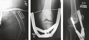
Figure 3.1 80-year-old woman with left femur fracture stabilized by a femur fracture splint and later by femur fracture traction.

Figure 3.2 65-year-old woman with healing patellar fracture stabilized by two cancellous partially threaded bone screws and tension band wires. A hinged knee brace stabilizes the knee.

Figure 3.3 Metallic wrist splint. 50-year-old woman with acute distal radius fracture.

Figure 3.4 Dorsal blocking splint. The patient suffered a volar plate injury to his ring finger from an electrical shock while working on a fish tank!
Casts and splints are composed of many materials, including plaster of Paris, synthetic casting material, and metal. Plaster of Paris is most frequently used to make splints and casts, because it is inexpensive, easy to mold, “breathable,” and absorbent (Figure 3.5). Synthetic casting materials are lighter and stronger, but they are more expensive and non-absorbent (Figure 3.6).

Figure 3.5 (A) Plaster cast. From Benjamin & Lund, 1994. (B,C) Plaster cast. 50-year-old female with acute distal radius fracture (same patient with the metallic splint).
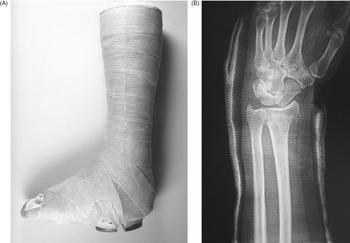
Figure 3.6 (A) Fiberglass cast. From Benjamin & Lund, 1994. (B) 60-year-old woman with healing distal radius fracture.
Casts and splints can be used either for temporary immobilization of an extremity, or they can be used for definitive treatment of an extremity fracture. They are often combined with internal fixation to provide additional support and protection of the extremity. Braces are also used to limit the range of motion of a joint after surgery or after trauma. In many cases, percutaneous pins (“Kirschner or K-wires”; Figure 3.7) are used in combination with a plaster cast to achieve treatment similar to an external fixator, so-called “pins in plaster” (Figure 3.8).

Figure 3.7 50-year-old woman with a distal radius fracture immobilized by four Kirschner wires (K-wires). There is also an ulnar styloid fracture.

Figure 3.8 Five K-wires stabilize a distal radius fracture with a cast in place.
External and Internal Traction Devices
Skeletal traction is the pulling on a bone through a pin or wire inserted into the bone. The pulling is used to reduce and stabilize a fracture. It is most commonly used in the lower extremity. Traction devices are applied along the long axis of the bone. They align the bone fragments and provide a degree of stability (Figures 3.9 and 3.1). Traction devices work only when the bone fragments are still connected to soft tissues. Skeletal traction entails the insertion of either a Kirschner (K)-wire or Steinman pin through the bone. The Kirschner wire has a smaller diameter and produces less injury to the soft tissues than does the Steinman pin, but it requires the use of a tensioned traction bow. Steinman pins come in a variety of sizes. Both Kirschner wires and Steinman pins can be smooth, partially threaded, or fully threaded. The threaded pins are associated with a more traumatic insertion than the smooth pins, but they are less likely to loosen over time.

Figure 3.9 There is a Kirschner wire inserted through the proximal tibial diaphysis with an external metallic traction device.
The most common indication for skeletal traction is a femoral fracture (Figure 3.1). Less commonly, skeletal traction is used for humeral fractures as well as some other lower-extremity fractures and dislocations. Sometimes, intraoperative skeletal traction is used for the reduction of a distal radius fracture (Ruedi et al., 2007; Wiss, 2013).
Traction pins for the lower extremity are placed in one of three sites: the supracondylar femur, proximal tibia, or in the calcaneus. Possible complications with supracondylar traction are quadriceps injury, neurovascular injury, and infection. Calcaneal traction, while not uncommon, should ideally be avoided, because it has a high infection rate (Figure 3.10). When a traction pin, fixation pin, or fixator pin has been removed from the bone, a lucent, hollow cylindrical track is left in the bone, a so-called ghost tract (Figure 3.11). The indications, technique, and complications with lower-extremity traction pins are nicely summarized by Althausen and Hak (2002).

Figure 3.10 Calcaneal traction.

Figure 3.11 Calcaneal ghost tract from removal of traction pin.
The Suzuki frame and Suzuki fixator are specialized devices for reducing and stabilizing complex intraarticular finger fractures. Rubber bands generate traction between two K-wires placed into the bone on either side of the fracture (Figures 3.12 and 3.13). Other specialized traction devices are also used for finger and wrist traction (Figure 3.14).
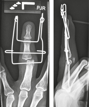
Figure 3.12 Suzuki frame. 41-year-old man with chronic fracture dislocation of the left ring finger proximal phalanx.

Figure 3.13 Suzuki fixator. 53-year-old woman with comminuted fracture involving the proximal portion of the left little finger middle phalanx.

Figure 3.14 External traction wire devices have been placed on the 1st–4th fingers to reduce and stabilize a distal radius fracture.
External Fixation
An external fixator is an externally applied device with bone screws or pins designed for the stabilization and immobilization of open long-bone fractures. It provides fracture fixation based on the principle of splinting. External fixators are the only system that allows the surgeon to control the flexibility of the fixation. External fixators are the standard in treating open fractures with substantial soft-tissue injuries that require vascular procedures, fasciotomy, soft-tissue flaps, or multiple debridements to avoid additional damage to an already compromised limb.
The other indications for the application of an external fixator are polytrauma; fractures in children to avoid pin fixation through the growth plate; temporary joint bridging before later open reduction and internal fixation (ORIF); and arthrodesis of the ankle, elbow, or knee. In these latter cases, external fixators are especially indicated in acute or chronic infections, in limb-lengthening procedures, and occasionally after corrective osteotomies (Benjamin & Lund, 1994; Berquist, 1995; Freiberg, 2001; Hunter & Taljanovic, 2001; Ruedi et al., 2007; Wiss, 2013).
External fixators are made of connecting rods with pins, screws, or wires (Schanz screws, Steinman pins, Kirschner wires) that are placed percutaneously into the bone above and below the fracture site. These pins, screws, or wires are connected by various clamps to the external fixation rods which are composed of stainless steel or carbon fiber.
There are three basic types of external fixators: (a) standard pin (or uniplanar) fixator (Figures 3.15 and 3.16), (b) ring fixator (Figure 3.17), and (c) hybrid fixator (Figure 3.18). Standard uniplanar external fixators consist of percutaneously placed pins that are connected to an external rod. Proper pin or screw placement is very important. These pins or screws should penetrate the near cortex and medullary canal and engage the far cortex without penetrating the muscle compartment. Joint penetration by any of these pins must be avoided. Standard uniplanar fixators can be used for almost every long-bone fracture except those involving the proximal femur or humerus. They are commonly used for the stabilization of complex distal radius fractures. The pins are placed in the distal radius and second metacarpal shaft. This technique uses the surrounding soft tissues or ligamentotaxis to provide indirect stabilization of the fracture. Uniplanar external fixators have a limited use in temporary stabilization of pelvic fractures (Figure 3.19).
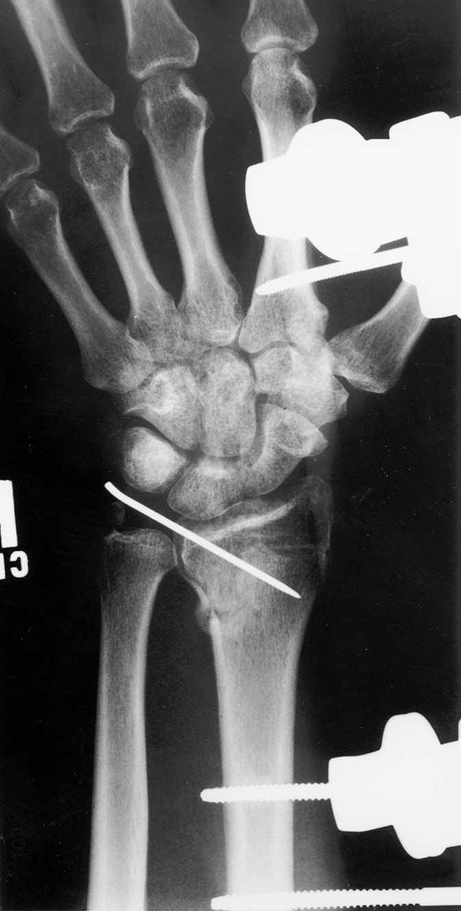
Figure 3.15 Uniplanar external fixator. External fixator used to treat a distal radius fracture (which also has a percutaneous pin in it). There are unilateral threaded pins in the radius and in the index finger metacarpal.
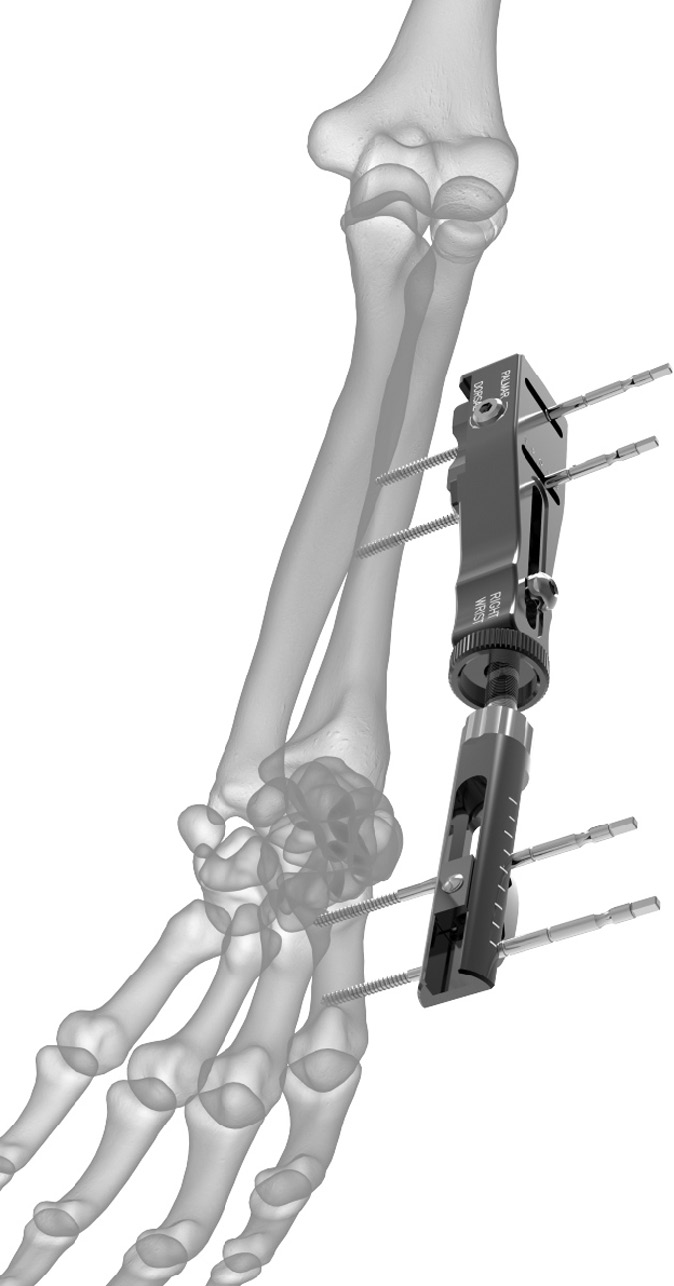
Figure 3.16 Stableloc external fixation system. This system is designed to stabilize otherwise unstable distal radius fractures. Image from Acumed.
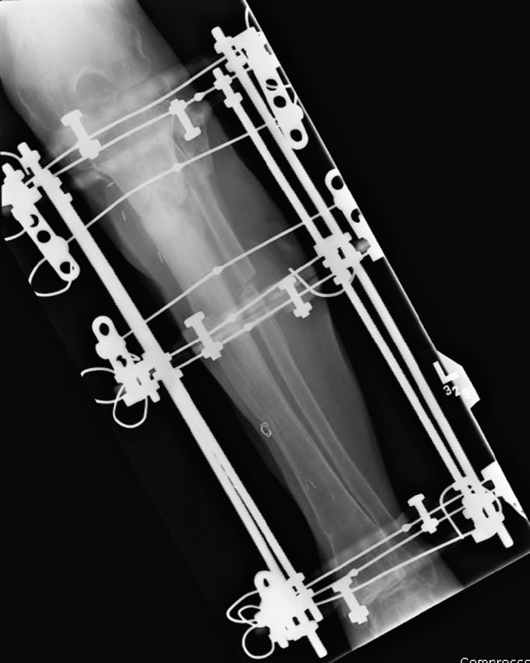
Figure 3.17 Ring (Ilizarov) external fixator. The fixator stabilizes a healing tibial fracture and a fibular osteotomy.

Figure 3.18 Hybrid external fixator. 57-year-old man with chronic fracture deformities treated by tibial and fibular osteotomies and placement of a hybrid external fixator.
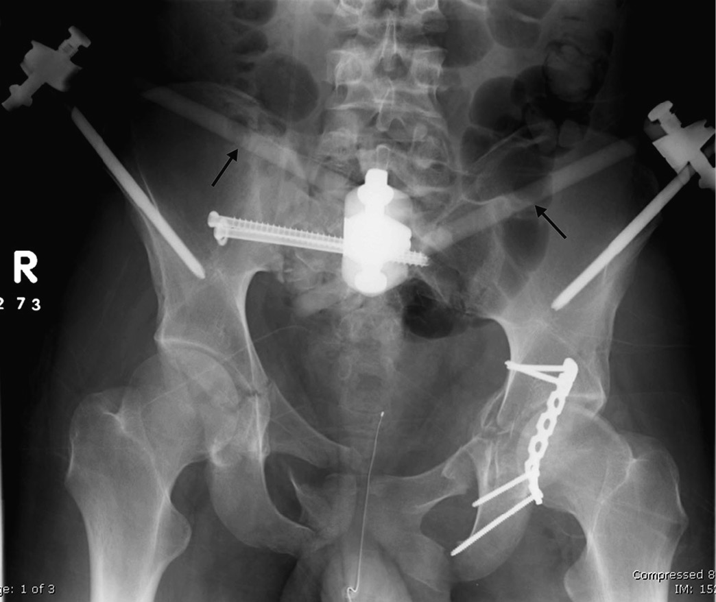
Figure 3.19 Uniplanar external fixator. Patient with multiple bilateral pelvic fractures. There is a uniplanar fixator with Schantz pins that transfix both iliac bones with carbon-fiber interconnecting rods (arrows). Two cancellous cannulated screws (proximal fully threaded, distal partially threaded with a washer) transfix the right sacroiliac joint and right sacral fracture. There is a reconstruction plate with four fully threaded cortical screws transfixing the posterior wall of the left acetabulum.
Ring fixators are made of thin wires under tension that are attached to circular or semicircular rings or frames. This technique was introduced by the Russian surgeon Ilizarov for limb-lengthening procedures. Currently, it has broader applications. The term Ilizarov fixator is frequently used for any type of ring fixator (Figure 3.17) (Benjamin & Lund, 1994; Berquist, 1995; Freiberg, 2001; Hunter & Taljanovic, 2001; Ruedi et al., 2007).
The third type of external fixator is called a hybrid fixator (Figure 3.18). It represents the combination of ring and standard uniplanar fixators. It is commonly used for treatment of the proximal and distal tibial fractures that are close to the joint. This fixator is made of a 3/4 ring proximally, which is attached to the bone by Kirschner wires. The ring is connected to a unilateral external rod, which is attached to the distal bone shaft by Schanz screws.
The adequate care of pin-track sites is important and starts at the day of placement. Daily cleansing and disinfection is necessary to minimize pin-track infection. Radiography is used to evaluate for pin loosening, breakage, and infection. Visualization of the entire device is frequently limited because of the overlapping frame, and additional views and even fluoroscopic evaluation may be needed for adequate assessment of possible complications (Benjamin & Lund, 1994; Berquist, 1995; Freiberg, 2001; Hunter & Taljanovic, 2001; Ruedi et al., 2007; Wiss, 2013).
Pinless fixators are sometimes used for tibial fractures, but they are less stable. With these fixators, the medullary canal is not penetrated because the clamps (forceps) are anchored into the cortex only. This type of fixation allows later safe intramedullary nailing (Ruedi et al., 2007).
Internal Fixation … Pins, Wires, and Screws
Since the late 1950s, open reduction and internal fixation (ORIF) has been used to treat fractures. It enables rapid restoration of bone anatomy and early patient mobilization to overcome the limitations encountered when fractures are treated with skeletal traction or cast immobilization (Benjamin & Lund, 1994; Freiberg, 2001; Hunter & Taljanovic, 2001; Ruedi et al., 2007).
The main goal of internal fixation is the achievement of prompt and, if possible, full function of the injured limb, with rapid rehabilitation of the patient. The majority of internal fixation implants are currently made of stainless steel. Occasionally, less strong but biologically superior and more elastic titanium implants are favored.
Numerous devices are available for internal fixation. These devices can be roughly divided into a few major categories: (a) wires, (b) pins and screws, (c) plates, and (d) intramedullary nails or rods. Staples and clamps are also used occasionally for osteotomy or fracture fixation (Benjamin & Lund, 1994; Berquist, 1995; Craig et al., 2001; Freiberg, 2001; Hunter & Taljanovic, 2001; Parker & Stockton, 2001; Ruedi et al., 2007; Stover, 2001; Wiss, 2013).
Pins
Fixation pins come in many designs and sizes and can be smooth or threaded. Among the most commonly used fixation pins are Kirschner (K)-wires (Figures 3.7 and 3.8) and Steinman pins (Figure 3.20). These devices are mainly used for temporary fixation of fracture fragments during fracture reduction or to attach skeletal traction devices. Sometimes, they act as guides for the accurate placement of larger cannulated screws.
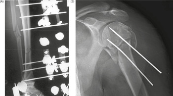
Figure 3.20 (A) Uniplanar external fixator with Steinman pins. The unilateral pins just penetrate the far cortex and are connected with radiolucent rod. The fixator is immobilizing a tibial fracture. From Benjamin & Lund, 1994. (B) Two Steinmann pins stabilize a comminuted left humeral head and neck fracture.
Percutaneously placed Kirschner wires commonly protrude through the skin for ease of later removal. Occasionally, pins are used for definitive fracture treatment and should be especially watched for migration. The Steinman pin is also occasionally used for wrist arthrodesis (Jebson & Adams, 2001). On rare occasions pins may be used for other applications, such as tendon reconstruction or lengthening (Figure 3.21).

Figure 3.21 Achilles tendon lengthening pin. 50-year-old woman with chronic juvenile arthritis.
It should be noted the terms pins and wires are commonly used interchangeably and inconsistently. Pins are more often thought of as straight, thin, metallic rods typically inserted so as to retain their straight form. However, they can be cut and bent for a given treatment situation. Wires are most often thought of as thinner metallic rods easily bent and shaped, similar to common wire used around the house or in the garden. Cables and bands are larger, more rigid wires.
Wires
Wires are sometimes used alone, but more commonly in combination with other orthopedic fixation devices. They are of various diameters and can be braided. Wires are frequently used to reattach osteotomized bone fragments (i.e., the greater trochanter to the femur or the olecranon process to the ulna). In combination with pins or screws, wires are sometimes used to create a tension band, which uses distractive muscular forces to create compression at the fracture site (Figures 3.22 and 3.2).

Figure 3.22 Tension band wire. Tension band fixation of an olecranon fracture using a cancellous screw. The looped wire transforms the distractive pull of the triceps into compression at the fracture site.
Wires are used to suture bone and soft tissue, and they occasionally break (Figure 3.23). However, if there is no loss of bone fragment position, breakage of wires is usually of little significance. Circumferential cerclage wires are commonly used in conjunction with intramedullary fixation to stabilize long-bone fragments and stems of prostheses or fixation plates (Figure 3.24). One of the potential complications with cerclage wires is interruption of the periosteal blood supply with subsequent osteonecrosis or fracture nonunion (Benjamin & Lund, 1994; Berquist, 1995; Freiberg, 2001; Hunter & Taljanovic, 2001; Ruedi et al., 2007; Wiss, 2013).

Figure 3.23 Broken trochanteric wire. A cemented total hip arthroplasty has a trochanteric osteotomy fixed with wires. The wire is broken laterally. The arrows point to evidence of polyethylene wear in the acetabulum.

Figure 3.24 Cerclage wires. A long stem bipolar hip prosthesis has cerclage wires in the diaphysis of the femur.
Screws
A variety of screws are used in everyday orthopedic practice. The main parts of a screw are the screw head, which is its bulbous end and the part engaged by the screwdriver, and the shank or core, which can be of variable diameter and is partially or fully threaded. The distance between the threads is called “pitch” (Figure 3.25).

Screws are of different sizes and can be self-tapping (which have cutting ends) or non-self-tapping. Non-self-tapping screws are easier to insert and remove, but they are not the best choice for fixing fractures in regions with a thin cortex. Some screws have a “standard” point and others a “trocar” point. Screws are commonly used in combination with plates and nails or rods. The use of different types and designs of screws depends on the surgeon’s preference (Benjamin & Lund, 1994; Berquist, 1995; Freiberg, 2001; Hunter & Taljanovic, 2001; Ruedi et al., 2007; Wiss, 2013).
There are two basic types of fixation screws, cortical and cancellous, according to the Arbeitsgemeinschaft fur Osteosythesefragen – known to English-speaking countries as the Association for the Study of Internal Fixation (ASIF). Cortical bone screws are often fully threaded and usually have a smaller thread diameter and pitch (Figure 3.26). Cortical screws are designed to be used in the diaphysis.

Cancellous bone screws are intended to cross long segments of cancellous bone. They typically have deeper threads, larger thread diameters, and a greater pitch than cortical screws. Cancellous screws are usually partially threaded with threads only on their ends (Figures 3.22 and 3.27). Occasionally, cancellous screws can be fully threaded (Ruedi et al., 2007).
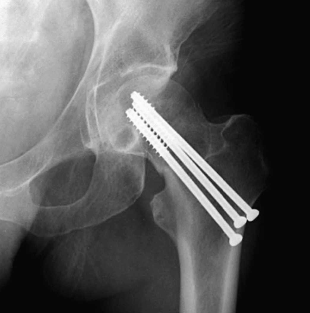
Figure 3.27 Hip cannulated cancellous fixation screws.
Schanz screws have a larger core diameter and less deep self-cutting threads, providing better buttressing against forces that act perpendicular to the long axis of the screw (Figure 3.15). There are other types of diaphyseal unicortical locking screws that are used with plates to provide better anchorage and which can function as a fixed-angle device (Ruedi et al., 2007).
A screw that crosses a fracture line (ideally, perpendicular to the fracture line) is called an “interfragmentary” screw or “lag” screw. This screw provides compression between the fracture fragments to enhance fracture stability and promote healing. Sometimes a lag screw is more specifically defined as an interfragmentary screw with a gliding hole in the near (cis) cortex and a threaded hole in the far (trans) cortex.
Fully threaded cortical interfragmentary screws are used in the diaphysis of bones, because they are easier to remove than partially threaded cancellous screws. Sometimes, an interfragmentary screw is placed through a fixation plate. Interfragmentary screws are preferred in the fixation of articular fractures to obtain anatomic reduction and adequate stability. Interfragmentary screws are also preferred for treating juxtaarticular fractures.
Self-tapping screws, which have cutting ends, are not recommended for use as interfragmentary screws because removal and reapplication of the screw may be needed. Interfragmentary screws are used occasionally to treat open fractures (i.e., in case of very long oblique spiral fractures or in the presence of a large well-vascularized third fragment that requires fixation) (Benjamin & Lund, 1994; Berquist, 1995; Freiberg, 2001; Hunter & Taljanovic, 2001; Ruedi et al., 2007).
In certain situations, a washer (metallic ring) is used with a screw to prevent the screw head from sinking into the bone. Washers enhance the compressive area of a screw in regions of thin cortex, and they prevent fractures under the screw (Figure 3.28).

Figure 3.28 Dynamic compression hip screw, partially threaded cannulated cancellous fixation screw and washer.
Loosening of well-placed screws is induced by micro motion at the interface between the thread and bone. From a radiologic standpoint, it is important to observe and report possible complications including screw breakage, loosening, or change in position (Benjamin & Lund, 1994; Hunter & Taljanovic, 2001; Ruedi et al., 2007). A screw that is used to stabilize the distal tibiofibular syndesmosis is called a syndesmotic screw. This screw is placed across the distal tibiofibular joint parallel and 1–2 cm proximal to the joint line. One or more syndesmotic screws can also be placed through the holes of a fibular fixation plate (Figures 3.29 and 3.30). Syndesmotic screws are usually removed 6–12 weeks after placement, after the interosseous membrane has healed (Benjamin & Lund, 1994; Berquist, 1995; Freiberg, 2001; Hunter & Taljanovic, 2001; Ruedi et al., 2007).

Figure 3.29 (A) Six-hole dynamic compression plate (DCP) and syndesmotic screw. (B) Locking low-contact DCP and screws with two fully threaded syndesmotic screws. A plaster splint is also present about the bimalleolar fracture.

Figure 3.30 Dynamic compression plate and syndesmotic screws as well as two fully threaded cortical medial malleolus screws.
Cannulated screws have a hollow shank, which allows them to be placed more exactly over a guide pin (Figure 3.31). They are commonly used for fixation of subcapital hip fractures and may be inserted percutaneously with fluoroscopic guidance (Figure 3.27). This surgery is commonly performedby using a fracture table to provide traction and maintain reduction during the fixation (Benjamin & Lund, 1994; Berquist, 1995; Freiberg, 2001; Hunter & Taljanovic, 2001; Ruedi et al., 2007).

Figure 3.31 (A) Cannulated fixation screws. Image © Smith & Nephew. Used with permission. (B) Cannulated screw with threaded-tipped guide pin and Herbert screw.
A special type of screw used in the treatment of intertrochanteric proximal femur fractures is called a dynamic compression screw (device) consisting of a large lag screw with distal threads that is inserted into the femoral head and neck. This screw fits into the barrel of a side plate, which is secured to the femoral shaft with multiple cortical screws. The lag screw can slide within the barrel, which results in compression of the fracture site as the patient ambulates (Figure 3.32) (Benjamin & Lund, 1994; Berquist, 1995; Freiberg, 2001; Hunter & Taljanovic, 2001; Ruedi et al., 2007). If the fracture settles, the lag screw slides within the barrel preventing the screw from piercing the femoral head and entering the hip joint space.

Figure 3.32 (A) Hip dynamic compression screw set. 1, lag screw; 2, compression screw; 3, barrel and side plate. From Benjamin & Lund, 1994. (B,C) Dynamic compression hip screw.
Large spiral or helical screws are sometimes used to secure femoral neck fractures, acting as a dynamic compression screw. This design is also used in other circumstances, such as a distal locking screw placed in an intramedullary rod (nail) (Figure 3.33).

Figure 3.33 Blade spiral (helical) distal locking screw. There are also two cortical distal locking screws, an intramedullary rod (nail), and skin staples.
Another “special” screw is a Herbert screw, which was originally designed for the fixation of scaphoid fractures (Figure 3.34). Currently, this screw has a broader application. The Herbert screw has threads of different pitch at both ends, with an unthreaded central shank. It does not have a head. It acts as a countersink, allowing different threads at its ends to draw the fracture fragments together (Benjamin & Lund, 1994; Herbert & Fisher, 1984; Hunter & Taljanovic, 2001; Ruedi et al., 2007). It is sometimes said to have cancellous threads on one end, while the other end has a larger diameter with cortical threads.

Figure 3.34 Herbert screws. (A,B) There is a different screw pitch on each end with headless (recessed) slot for the screwdriver. (C) There is a healing scaphoid fracture, and a fiberglass splint is in place.
A similar screw is the Acutrak screw. It is headless with variable thread pitch on either end, but it does not have an unthreaded central shank (Figures 3.35 and 3.36). It is very commonly used for the treatment of finger and wrist fractures. The Smart (toe) implant is a product of Stryker specifically designed for interdigital fusion of fingers or toes and other small bones. It is sometimes used in conjunction with K-wires and small fixation screws (Figure 3.37).

Figure 3.35 Acutrak screw. (A) The screw stabilizes a scaphoid fracture. (B,C) The Accutrak screws are used for arthrodesis of the distal interphalangeal joints of the right index and long fingers in a woman with severe osteoarthritis.

Figure 3.36 Acutrak screws and endobuttons. 64-year-old woman with thumb “tight-rope” surgery using Endobuttons and Acutrak screws. The trapezium has been resected.

Figure 3.37 Smart toe implants. 71-year-old woman with surgery for recurrent hammer toes. There are Smart toe implants fusing the right second and third interphalangeal joints. A small cortical screw goes through the second metatarsal neck, and there are K wires in the fourth and fifth toes.
For capsular, tendinous, and ligamentous repairs, a variety of anchor screws (suture anchors) are used (Figures 3.38 and 3.39). These screws have barbs and hooks for soft-tissueor bone attachment and allow for suturing of ligaments to the anchor, which is then placed in the bone (Benjamin & Lund, 1994; Hunter & Taljanovic, 2001; Ruedi et al., 2007).

Figure 3.38 Suture anchors in glenoid rim.

Figure 3.39 (A) Suture anchors (anchor screws) in humeral head. Multiple suture anchors are present in the left shoulder humeral head for tacking down the joint capsule in a patient with recurrent shoulder dislocation. (B) Suture anchor (anchor screw) in calcaneus.
Other devices used for soft tissue anchoring are Endobuttons. An Endobutton is a cortical bone fixation device with a continuous loop suture and no fixation knot (Figure 3.40). Endobuttons were designed for anterior cruciate ligament reconstruction and fixation, but are also used for other ligamentous repairs (Figures 3.41 and 3.36) (Melville et al., 2015). There is direct fixation of the repair graft onto a small, metallic, button-like device through which continuous loop suturing is used, with the fixation device secured directly to the external surface of cortical bone.

Figure 3.40 Endobuttons.

Figure 3.41 Anterior cruciate ligament (ACL) reconstruction with bioabsorbable tibial interference screw and femoral Endobutton. 29-year-old man with ACL repair. immediate postoperative images with soft tissue and intraarticular gas from the recent surgery. There is also a fully threaded tibial tuberosity cortical screw.
Fixation techniques for anterior cruciate ligament (ACL) grafts continue to evolve (Figure 3.42). The Kurosaka screw, which is also called an interference screw, is designed to anchor the ACL graft into the lateral femoral condyle and proximal medial tibial metaphysis bone tunnels (Kurosaka et al., 1987) (Figures 3.43 and 3.44). This screw is headless, short, and broad. There are a variety of designs for interference screws that act as anchors for the fixation of ACL grafts (Beevers, 2003; Pena et al., 1996). These screws can be metallic or bioabsorbable and radiolucent (Figure 3.45). Aside from interference screws, there are other devices used for the fixation of the ACL graft, including buttons, washers, staples, cross pins, polyester titanium buttons, and suture posts (Figure 3.46).

Figure 3.42 Anterior cruciate ligament (ACL) artificial graft. Woven Gore-Tex ACL substitute.

Figure 3.43 (A) ABSOLUTE interference screw. From DePuy-Synthes. © DePuy Synthes 2016. All rights reserved. ABSOLUTE™ is a trademark of DePuy Synthes. (B) Biosure intereference screw. Image © Smith & Nephew. Used with permission.

Figure 3.44 Interference (Kurosaka) screws. The screws are used to anchor anterior cruciate ligament graft in femoral and tibial metaphysis. Note the multiple osteochondromas (familial exostosis).

Figure 3.45 Anterior cruciate ligament (ACL) fixation. Shown are an “interference (Kurosaka) screw” for the ACL, and fixation staples for the medial collateral ligament and the patellar tendon/tibial tuberosity.

Figure 3.46 Anterior cruciate ligament (ACL) reconstruction with bioabsorbable tibial interference screw and femoral Endobutton. 29-year-old man with ACL repair. Immediate postoperative images with soft tissue and intraarticular gas from the recent surgery. There is also a fully threaded tibial tuberosity cortical screw.
The radiographic appearance of the knee after ACL reconstruction is usually initially evaluated with standard radiographs (Manaster et al., 1988). On the lateral radiograph, the tibial osseous tunnel should begin distally near the tibial tuberosity, course posteriorly, and exit the tibial articular surface immediately anterior to the anterior tibial spine. On the frontal radiograph, the tibial tunnel begins in the medial tibial side, courses laterally and proximally, and exits the articular surface at the intercondylar eminence of the tibial plateau.
The appropriately placed ACL graft has an oblique orientation and on sagittal oblique magnetic resonance images is posterior to the intercondylar roof line (Blumensaat line). On the lateral radiograph, the femoral osseous tunnel extends from the intersection of two lines, which represent the posterior femoral cortex and the intercondylar roof. On the frontal radiograph, the femoral tunnel begins laterally, just superior to the lateral femoral condyle, and emerges on the superolateral aspect of the intercondylar notch. Once standard radiographs have been obtained, the integrity and possible complications of the ACL graft are evaluated frequently with magnetic resonance imaging (Martin et al., 2002; Resnick et al., 2007).
Plates
Most fracture fixation plates are made of stainless steel or titanium and can be used for both flexible and rigid fracture fixation (Figure 3.47). Flexible fixation means the fracture fragments displace in relation to each other when a load is applied across the fracture site. There is appreciable interfragmentary movement under a functional load. The majority of the fracture fixation methods commonly employed use flexible or “biologic” fixation. Fracture healing under flexible fixation typically occurs by means of callus formation.

Figure 3.47 Fracture fixation plates. (A) One-third tubular plate; (B) Dynamic compression plates (DCP); (C) T-plate; (D) Reconstruction plates.
Compression fixation techniques, which are less common, produce rigid fixation. Rigid fracture fixation with plates and screws is desirable for fractures that involve an articular surface. Articular fractures require exact anatomic reduction and stable fixation to avoid development of abundant callus. This is important because unevenness of the joint surface and presence of callus formation at the articular surface lead to patient discomfort and often development of early and progressive osteoarthritis (Ruedi et al., 2007).
Bridging of any fracture with a stiff splint reduces mobility of the fracture fragments, which allows minimal displacement under a functional load. Although rigidity of the fracture fixation contributes to reducing fracture mobility, the only technique that can effectively abolish motion at a fracture site is interfragmentary compression of the fracture fragments. However, with proper placement and use of plates and screws there is often enough stability to diminish the strain at the fracture site to such extent there is direct healing without formation of visible callus.
Terminology commonly used with fracture plating is “compression plating” and “neutralization plating” (Figures 3.48 and 3.49). Compression plating applies compression to the fracture ends. Severely comminuted fractures and/or fractures with bone loss prevent compression plating. In these cases, thefixation plate is applied in neutral mode to hold the fracture fragments in place without compression during healing. No matter the case, frequently not all the screw holes in a fracture fixation plate are filled.


