Basic Physics and the CT Camera
Kavitha M. Chinnaiyan
Laxmi S. Mehta
Ralph E. Gentry
Gilbert L. Raff
Overivew of Computed Tomography
Dramatic improvements in multi-detector computed tomography (MDCT) technology over the last decade have vastly increased its clinical utility and popularity for cardiac imaging. Because of its easy acquisition, improved spatial and temporal resolution, and flexible interpretation in three dimensions, coronary CT angiography is now considered by some to be the new alternative to invasive angiography.
Evolution of CT Scanners
The basic principle of the CT scanner is the use of a thin, fan-shaped X-ray beam that passes through the body to a detector array, which then measures the degree of the X-ray transmission. This data is then digitized into picture elements called pixels. A pixel is a small region of a grid of the imaged object whose size depends on the size of each detector and its surrounding lead shielding (collimator). Various shades of gray are assigned to the pixels representing the imaged structures. This data is reconstructed into an image using a computer program based on mathematical back-calculation of the attenuation from the body (“algorithmic back-projection”). The anatomic image data can be displayed on computer workstations and can be flexibly sliced and rotated, and displayed in various two- and three-dimensional formats to aid in interpretation, which is critically important in the tortuous coronary circulation.
The first CT scanner was introduced for clinical use in 1973. Since then, the CT technology used for routine clinical diagnostic examinations has progressed through four generations of development. The first generation of CT scanners consisted of an X-ray tube that generated a thin “pencil beam” and a single detector. Both the X-ray tube and the detector moved as an assembly in a rectilinear path across the gantry. A series of 1-degree rotations-translations across a 180° arc were necessary to produce an image, resulting in long scan times. Scan time with the second-generation CT systems using a fan-shaped X-ray beam and a group of detectors (detector array) decreased scan times considerably. Third-generation systems use a fan-shaped X-ray beam and a detector array arranged in a curved arc rather than a straight line. This results in rotation of the X-ray tube/detector assembly around the patient, rather than a rectilinear path across the patient. Continuous rotation (the current third-generation) scanners were introduced to eliminate the problem of winding up of the high-tension cable from the high frequency generator that required stopping the gantry frame and reversing direction with each subsequent scan. Continuous rotation scanners use
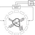
a large rotating ring that surrounds the gantry aperture (the slip ring) and eliminates the winding up of the cable. Electrical brushes convey electrical power and data to the components mounted on the rotating ring. The slip ring conveys scanning instructions from the host computer to the gantry components and may serve to facilitate image reconstruction by conveying information about measured attenuation data from the patient to the computer. The combination of rotation and movement of the patient produces a spiral or helical path of the X-ray tube with respect to the patient. This results in extremely fast scan times. The majority of medical CT scanners in use today, including all cardiac scanners, are third-generation spiral technology. Fourth-generation scanners consist of a fan-shaped X-ray beam with detectors forming a complete circle around the gantry in a ring configuration. In these scanners, the X-ray tube rotates while the detectors are stationary. Because the detectors completely surround the gantry, the number of detectors needed is large.
a large rotating ring that surrounds the gantry aperture (the slip ring) and eliminates the winding up of the cable. Electrical brushes convey electrical power and data to the components mounted on the rotating ring. The slip ring conveys scanning instructions from the host computer to the gantry components and may serve to facilitate image reconstruction by conveying information about measured attenuation data from the patient to the computer. The combination of rotation and movement of the patient produces a spiral or helical path of the X-ray tube with respect to the patient. This results in extremely fast scan times. The majority of medical CT scanners in use today, including all cardiac scanners, are third-generation spiral technology. Fourth-generation scanners consist of a fan-shaped X-ray beam with detectors forming a complete circle around the gantry in a ring configuration. In these scanners, the X-ray tube rotates while the detectors are stationary. Because the detectors completely surround the gantry, the number of detectors needed is large.
Multi-row detector scanners were introduced to decrease scan time without compromising anatomical data. These scanners consist of multiple parallel detector arrays and a thick X-ray beam. Each detector array is in turn composed of several hundred detectors arranged along a curved arc. MDCT scanners collect data from multiple anatomical slices in each rotation of the X-ray tube, leading to faster scan times because of wider coverage. Cardiac imaging became practical once breath-hold was reduced to 20 seconds or less (16-slice technology). This has been improved further by the wide availability of 64-slice scanners that have reduced breath-hold times to 15 seconds or less for most patients.
In the MDCT systems, an X-ray tube mounted on a rotating gantry generates the X-ray photons and an array of detectors is positioned to receive the photons after they “go through” the patient situated in the bore of the gantry. The number of X-ray photons can be increased by increasing the tube current (mA) via a tungsten filament, typically to allow better tissue penetration and diminished image noise in patients with higher body mass indices. With the MDCT systems, the gantry rotates continuously and the table moves the patient through the imaging plane at a set speed. Scan pitch is the relative speed of the gantry rotation table speed, and is important for cardiac gating in the helical mode.
Thus, the faster the table speed, the wider the slices. For high-resolution cardiac imaging, very thin axial slices are required, i.e., lower table speed. The disadvantage of a low table speed is higher radiation exposure. The fastest available rotation time for MDCT systems is 333 milliseconds. Spatial resolution can be preserved by increasing collimator coverage and consequent lowering of the pitch. In the 64-slice systems with 0.625 mm collimation and table feed of 3.8 mm per rotation with the tube current at 120 kV, pitch is equal to 0.1 with an average scan time of 6–10 seconds.
Spatial resolution is the ability of the system to effectively depict and reproduce fine details within an image. Spatial resolution is dependent on slice thickness as well as the reconstruction matrix. Temporal resolution is the amount of time taken to acquire necessary scan data to reconstruct an image (Figure 5.1). For multiscan CT, temporal resolution depends on the time taken by the scanner to complete one gantry rotation, which can be modified using partial scan or “half-scan” reconstruction techniques. Half-scan reconstruction uses scan data from a 180° (in reality, 210° when the fan beam width is considered) gantry rotation to generate a singe axial image. This results in improved temporal resolution, i.e., 60% of the rotation speed of the scanner.
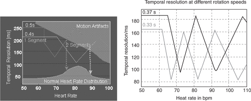 FIGURE 5.1. Effect of rotation speed on temporal resolution. Courtesy of Siemens AG Medical Solutions, Forchheim and Erlangen, Germany. |
Although development of 16- and 64-slice spiral CT systems has resulted in an increase in gantry rotation times (from 500 milliseconds to 330 milliseconds) and subsequent improved temporal resolution, the scanning algorithms of these systems display a nonlinear relationship with heart rate (Figure 5.2), making them sensitive to changes in heart rate during image acquisition. The 330 milliseconds per revolution rotation speed is close to the physical limits the components of the gantry assembly can endure. Because algorithmic back-projection requires only a half-scan (180° rotation) to produce a full image, the effective “shutter speed” of a 330-millisecond rotation scanner is approximately 165 milliseconds (Figures 5.3 and 5.4). This requires both heart rate
reduction (to 60–70 beats per minute) and heart rate stabilization to avoid image artifacts caused by motion (either blurring or “reconstruction” artifacts). Thus, in most patients, lowering of heart rates is achieved by pretreatment with beta-blocking drugs.
reduction (to 60–70 beats per minute) and heart rate stabilization to avoid image artifacts caused by motion (either blurring or “reconstruction” artifacts). Thus, in most patients, lowering of heart rates is achieved by pretreatment with beta-blocking drugs.
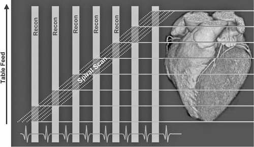 FIGURE 5.2. Scan speed synchronized to heart rate. Courtesy of Siemens AG Medical Solutions, Forchheim and Erlangen, Germany. |
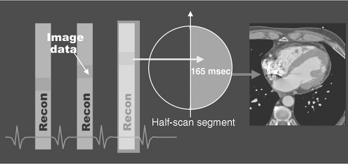 FIGURE 5.3. Single segment reconstruction. Courtesy of Siemens AG Medical Solutions, Forchheim and Erlangen, Germany. |
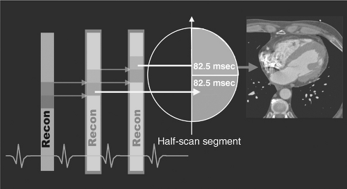 FIGURE 5.4. Multi-segment reconstruction. Courtesy of Siemens AG Medical Solutions, Forchheim and Erlangen, Germany. |
Dual-Source CT
The dual-source CT (DSCT) system is equipped with two X-ray tubes and two corresponding detectors mounted onto the gantry with an angular offset of 90°. One detector covers the entire scan field of view (50 cm), while the other detector covers a smaller, central field of view (26 cm). Each detector has 40 detector rows (32 central rows with 0.6 mm collimated slice width, and four outer rows with 1.2 mm collimated slice width). Two subsequent 32-slice readings with 0.6 mm collimated slice width are combined to one 64-slice projection with a sampling distance of 0.3 mm at the isocenter. Thus, 64 overlapping 0.6 mm slices per rotation are acquired, with a gantry rotation time of 0.33 seconds. The temporal resolution is either 83 milliseconds with a single R-R reconstruction, or 42 milliseconds with a segmented reconstruction algorithm combining data from two cardiac cycles. Dual-source CT enables reconstruction of cross-sectional images with a temporal resolution corresponding to one quarter of the gantry rotation time in the center of the gantry rotation, reducing the effective temporal resolution to approximately 83 milliseconds as of this writing. This generally permits artifact-free scanning without beta-blockers in most patients.
Image Formation
Cross-sectional images are obtained when the thin, fan-shaped X-ray beam passes through the body at many angles. The corresponding X-ray transmission measurements are collected by a detector array. Information entering the detector array and X-ray beam is collimated to produce thin sections while avoiding photon scatter. The data recorded by the detectors are digitized into picture elements (pixels) with dimensions that determine the effective resolution of the scanner. Thus, a scanner that produces pixels that are 0.6 mm by 0.6 mm will effectively produce resolution close to 0.6 mm in tissue. The third dimension, the thickness
of the slices, creates a third side to the cube (a volume-element or voxel), which is incorporated into a three-dimensional dataset incorporating everything within the thorax, or other body parts within the field of view. It is important that the third dimension (slice thickness) be equivalent to the other dimension of the pixel (producing an isotropic volume element or voxel) that is the same on all three dimensions. This allows accurate rotation of the processed image without anatomic distortion (see below). Grayscale values for voxels in the reconstructed tomogram are defined with reference to the value for water, called CT numbers or Hounsfield units (HU). The grayscale information contained in each pixel is reconstructed according to the attenuation of the X-ray beam along its path using a standardized technique called algorithmic back-projection. This back-projection is further filtered mathematically to avoid sharp artifacts, resulting in a filtered back-projection. Once this data is reconstructed, it can be flexibly sampled retrospectively within any plane using the multi-planar reformat technique.
of the slices, creates a third side to the cube (a volume-element or voxel), which is incorporated into a three-dimensional dataset incorporating everything within the thorax, or other body parts within the field of view. It is important that the third dimension (slice thickness) be equivalent to the other dimension of the pixel (producing an isotropic volume element or voxel) that is the same on all three dimensions. This allows accurate rotation of the processed image without anatomic distortion (see below). Grayscale values for voxels in the reconstructed tomogram are defined with reference to the value for water, called CT numbers or Hounsfield units (HU). The grayscale information contained in each pixel is reconstructed according to the attenuation of the X-ray beam along its path using a standardized technique called algorithmic back-projection. This back-projection is further filtered mathematically to avoid sharp artifacts, resulting in a filtered back-projection. Once this data is reconstructed, it can be flexibly sampled retrospectively within any plane using the multi-planar reformat technique.
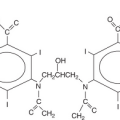
Differences in brightness of the image at different points will depend on physical density as well as the presence of atoms with a high difference in atomic number (for example, calcium, soft tissue, and water). The CT brightness of the image results from atoms absorbing (attenuating) the X-ray beam differently. Blood and soft tissue have similar densities and consist of similar proportions of the same atoms (hydrogen, carbon, and oxygen), whereas bone has an abundance of calcium and fat has abundant hydrogen. The higher the density of the constituent atoms, the brighter the structure on the CT images. Hence, calcium is bright white, air is black, and soft tissue (blood and muscle) is gray. Although non-contrast CT can readily distinguish blood from air, fat, and bone, it cannot distinguish blood easily from muscle or soft tissue. Because the lumen of the coronary arteries contains water-density blood adjacent to similar density muscle, in general the two cannot be distinguished on a non-contrast scan, whereas the high-density calcium is clearly visible. To distinguish blood from soft tissue (for example, lumen from wall of the coronary artery), injection of contrast is necessary. The absorption of the X-rays by calcium and iodine (elements of high atomic number) allows superb visualization of the lumen of the coronary arteries and coronary calcium as well, although calcium scoring must be done on a non-contrast scan. Hounsfield units may range from –1000 (air) through 0 (water) to +1000 (bone) because of differences in attenuation of X-ray. Coronary calcium caused by atherosclerosis generally measures 130–600 HU. Metal found in valves, wires, stents, and surgical clips can measure +1000 HU or greater.
Prospective Versus Retrospective Gating
Historically, CT imaging of the heart has been challenging, primarily because of continuous motion. The development of electrocardiograph (ECG)-synchronized MDCT scanning and reconstruction techniques now enables fast volume coverage as well as high spatial and temporal resolution. In addition, appropriate collimation size and scan acquisition speed should be chosen to minimize motion artifacts. Collimation size for CT calcium scoring as well as coronary angiography is 0.6–3 mm, with acquisition time of 50–250 milliseconds per image. However, this “ultra-fast” speed is not enough to eliminate cardiac motion. Hence, cardiac or ECG triggering is necessary to minimize cardiac and coronary motion during scan acquisition and to improve image quality. Cardiac motion is lower by nearly 30 milliseconds in early diastole, and thus, this interval is most favorable to obtain adequate images.
Related posts:

Stay updated, free articles. Join our Telegram channel

Full access? Get Clinical Tree


