Imaging of the Heart and Great Vessels: Introduction
The heart is often the “forgotten” structure in thoracic imaging studies. Yet a tremendous amount of information regarding cardiac structure and function can be gleaned from careful analysis of studies, regardless of whether they are dedicated to cardiac imaging. This chapter describes the normal radiographic appearance of the heart, pericardium, and great vessels (aorta and pulmonary vessels) and briefly outlines some of the more common pathologic entities in this organ system. Critical evaluation of the findings on the imaging examinations of this region is not possible without paying attention to the lungs, as these two organ systems mirror changes in each other. The most common abnormalities encountered in the cardiovascular system are hypertension, pulmonary arterial hypertension (usually secondary to chronic pulmonary disease), congestive heart failure, atherosclerotic disease, and valvular disease. Less common cardiac and great vessel diseases such as congenital heart disease, neoplasms, and diseases of the pericardium are described in less detail. The last topic, monitoring devices and postoperative changes, is one with which students should be familiar.
It is assumed that the student understands the basic normal anatomy of the cardiovascular system from the basic science and clinical years. At the completion of this chapter, the student should have an understanding of the wide range of imaging modalities used, an appreciation for the potential yield from these examinations, a basic knowledge of the normal imaging anatomy on the conventional radiograph, a familiarity with more common postoperative alterations, and the various monitoring devices that may be present in the intensive care unit (ICU).
Techniques and Normal Anatomy
A variety of techniques have been developed to evaluate the heart and great vessels (Table 3-1). In this section, we briefly describe the major tests used in imaging this system.
Conventional radiographs |
Posteroanterior (PA) and lateral |
Oblique |
Portable anteroposterior (AP) |
Computed tomography (CT) |
Echocardiography |
Transthoracic |
Transesophageal |
Magnetic resonance (MR) imaging |
Angiography |
Coronary arteriography |
Aortography |
Pulmonary arteriography |
Radionuclide imaging |
Positron emission tomography |
The most common imaging test for evaluating the heart and great vessels is the chest radiograph, which consists of an upright posterior-to-anterior (PA) and left lateral (LAT) projections. The terms PA and left lateral refer to the direction the x-ray beam takes through the body before it reaches the radiographic cassette. Chest radiographs are usually obtained with high kilovoltage and milliamperage to minimize exposure time and cardiac motion. When possible, the distance between the x-ray tube source and the film is at least 6 feet to minimize magnification and distortion.
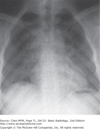
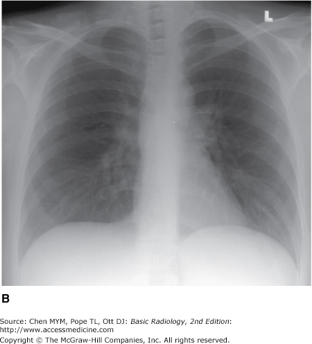
The examination is ideally performed with the patient at maximal inspiration. A good rule of thumb for estimating adequate inspiration is to be able to count 9 to 10 posterior ribs or 5 to 6 anterior ribs from the lung apices to the hemidiaphragms through the aerated lungs (Figure 3-1). When a chest radiograph is taken in the expiratory phase of respiration, the patient may appear to have cardiomegaly, vascular congestion, and even pulmonary edema. This appearance, however, is merely artifactual and caused by the lack of inspiration (Figure 3-2).
Figure 3-1.


Normal PA and lateral radiographs. (A) PA view of normal chest. RA, right atrium; RDPA, right descending pulmonary artery; RPA, right main pulmonary artery; SVC, superior vena cava; AA, aortic arch; DA, proximal descending thoracic aorta; LPA, left pulmonary artery; RV, right ventricle. (B) Lateral view of normal chest. RV, right ventricle; RSS, retrosternal clear space; AA, ascending aorta; LPA, left pulmonary artery; RPA, right pulmonary artery en face; IVC, inferior vena cava; LA, left atrium; LV, left ventricle.
Severely ill, debilitated patients or patients who cannot be transported to the radiology department can have their chest radiographs obtained with a portable x-ray machine. Patients in the ICU who have intravascular catheters or who are undergoing mechanical ventilation frequently have chest radiographs performed as a survey for complications that may not be revealed by physical examination or laboratory data. These examinations are done with the cassette placed behind the patient in bed and are therefore anterior-to-posterior (AP) projections. The technical factors, which are controlled by the technologist at the time of the examination, vary with the size of the patient and the distance of the radiographic plate from the x-ray source (or machine). An attempt is still made to obtain the examination during maximum inspiration, but this objective may be difficult to achieve in some patients, especially those who have dyspnea.
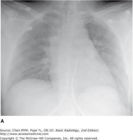
With the patient in the supine position, there is normally a redistribution of blood flow to the upper lobe pulmonary veins (cephalization), and the heart may appear enlarged relative to its appearance on the upright PA radiograph, because of magnification (Figure 3-3). Some patients are able to sit for their examinations, whereas others are radiographed in a semiupright position. Ideally, the technologist should mark the exact position of the patient when the radiograph is obtained, and the date and time of the examination should be recorded in all cases. Changes in patient positioning and ventilator settings can have substantial effects on the radiographic appearance and must be taken into account when evaluating any change in the radiograph from a previous study.
The chest radiograph, whether it is obtained in the upright, semiupright, sitting, or supine position, should almost always be the initial screening examination in the evaluation of the cardiovascular system. Because it is essentially a screening study, the chest x-ray must be correlated with the clinical symptoms and physical examination to determine the overall significance of the radiographic findings. This information is also used to decide if other imaging tests are appropriate and which ones will potentially result in the highest diagnostic yield. Decisions regarding further imaging also depend on the impact on the clinical management of the patient, the potential for treatment of any abnormality that may be discovered, the cost and availability of the technique, and the expertise of the interpreting radiologist.
The conventional radiograph is an excellent screening test for the patient suspected of having disease involving the heart and great vessels, because the overall anatomy of these areas is demonstrated well. Whenever possible, all radiographs should be reviewed with all prior relevant imaging studies. Even when a prior chest radiograph is not available, additional information may be ascertained by reviewing other prior images such as thoracic spine or rib-detail image when available. Advanced imaging studies such as computed tomography (CT) and magnetic resonance (MR) imaging can also be used to help clarify complex findings on chest radiographs.
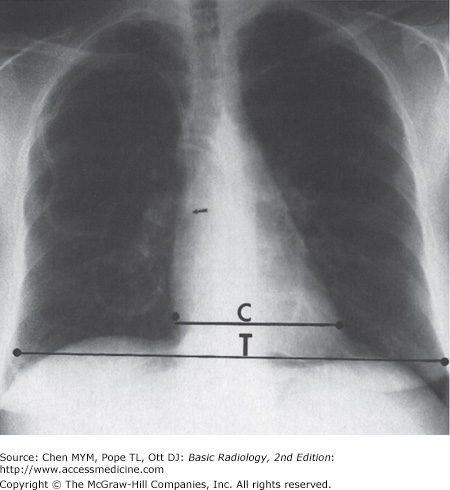
The normal cardiac silhouette size may be determined by the cardiothoracic ratio, a measurement obtained from the PA view. This ratio is calculated by dividing the transverse cardiac diameter (measured from each side) by the widest diameter of the chest (measured from the inner aspect of the right and left lungs near the diaphragm). The average normal value for this ratio in adults is 0.50, although up to 60% may be normal (Figure 3-4). A measurement over 50% is generally considered abnormal in an upright inspiratory-phase PA film, although this may not always be clinically significant. The cardiothoracic ratio cannot be reliably used for the AP projection of the chest, because the heart is magnified (see Figure 3-3). The size of the patient and the degree of lung expansion also should be considered. For instance, in a small person with a petite frame and a small thoracic cage, the heart size may be normal, but the cardiothoracic ratio may measure over 50%. Similarly, if the patient has pulmonary disease such as emphysema, the heart may be enlarged, but because of the overinflation of the lungs, the cardiothoracic ratio may still be normal. In clinical practice, most radiologists do not perform this measurement and rely on experience and “gestalt” to evaluate heart size.
The contours of the heart, mediastinum, and great vessels on the PA view should be evaluated on each chest film (see Figure 3-1 A). A reasonable approach is to begin in the upper right side of the mediastinum just lateral to the spine and below the right clavicle. The curved soft-tissue shadow represents the right border of the superior vena cava (SVC). The border of the SVC forms an interface with the lung and should not be confused with the right paratracheal stripe. Below the SVC is the right cardiac border formed by the right atrium. The inferior heart border, or base of the heart, is the area just above the diaphragm and is composed primarily of the right ventricle, although there is some contribution from the left ventricular shadow. The left ventricle makes up the majority of the apex of the heart, which points to the left of the spine. The origins of the right and left pulmonary arteries are generally well demarcated on the normal PA film as they emerge from the mediastinum. The most prominent and recognizable component of the right pulmonary artery, the right descending pulmonary artery (RDPA), is seen just to the right of the superior cardiac border and descends inferiorly. It can usually be easily followed until it branches. The left main pulmonary artery is less well defined, but its origin can usually be seen above and lateral to the left atrial appendage just before it branches. When enlarged, the main pulmonary artery may be seen superimposed over the left pulmonary artery and filling in the normal space between the left pulmonary artery and transverse aortic arch (the AP window). The aorta originates posterior and to the right of the main pulmonary artery, and the border of the ascending portion of the aorta can usually be seen superimposed on the inferior portion of the SVC. The majority of the transverse arch is not outlined by air and therefore cannot be seen as it crosses the mediastinum. However, the distal transverse and descending aorta can be seen to the left of the mediastinum as it turns inferiorly. The left border of the descending thoracic aorta should be followed down to the aortic hiatus. Any loss of this contour or any contour abnormality may indicate pathology and should be investigated. Dilation or ectasia, localized bulges, and calcification may occur within the aorta as a normal part of the aging process, but should be viewed as abnormal in younger individuals. Of course, the spine, ribs, adjacent soft tissues, and upper abdominal contents should all be scrutinized. The left atrium lies just inferior to the tracheal carina, but it is usually not visualized as a discrete structure on the normal PA view.
The lateral view of the chest also reveals important information regarding the cardiac contour (see Figure 3-1 B). Just behind the sternum there is normally a radiolucent area called the retrosternal clear space (RSS). This region represents lung interposed between the chest wall and the anterior margin of the ascending aorta. Any density present within the RSS may be due to an anterior mediastinal mass or postsurgical changes. The anterior border of the cardiac shadow is composed primarily of the anterior wall of the right ventricle. Right ventricular enlargement may also encroach into the retrosternal clear space. The posterior margin of the cardiac silhouette is formed by the left atrium and left ventricle. Just posterior and inferior to the left ventricle is a linear soft-tissue shadow leading into the heart formed by the inferior vena cava (IVC). The left ventricular shadow should not project more than 2 cm posterior to the posterior border of the IVC. The transverse aortic arch can usually be discerned on the normal lateral chest film as a smooth curving shadow originating anteriorly, crossing the mediastinum in a semilunar fashion, and then descending posteriorly as a linear shadow superimposed over the vertebral bodies. The left pulmonary artery (LPA) produces a similar curvilinear shadow just below the aortic arch before it branches. Just below the LPA, the left main/left upper lobe bronchus can be seen (projected end-on) as a round lucency. The right pulmonary artery (RPA) is seen en face down its lumen as an oval soft-tissue structure anterior to the bronchus intermedius and below and anterior to the left pulmonary artery.
Echocardiography uses high-frequency ultrasound to evaluate the heart and great vessels. The major indications for the technique are listed in Table 3-2. The examination provides a dynamic rendition of cardiac great vessel anatomy and, when combined with the Doppler technique, yields information regarding cardiac and great vessel blood flow (hemodynamics) as well. Because of the high frame rates inherent in ultrasonography, echocardiography can image the heart in a dynamic real-time fashion, so that the motion of cardiac structures can be reliably evaluated. Echocardiography is useful in assessing ventricular function, valvular heart disease, myocardial disease, pericardial disease, intracardiac masses, and aortic abnormalities (Figures 3-5 and 3-6). With Doppler technology, cardiac chamber function, valvular function, and intracardiac shunts frequently seen in congenital heart disease can be assessed. Combined Doppler echocardiography is a commonly performed procedure because it is relatively inexpensive and widely available, provides a wealth of information, is noninvasive, has no risk of ionizing radiation, and can also be performed at the bedside in critically ill patients. Furthermore, the results are immediately available because no special postexamination image processing is required. However, this technique is technically challenging and requires a great deal of operator expertise. Also, a small percentage of patients have poor acoustic windows that can severely degrade image quality. This disadvantage can be obviated by placing the sonographic probe in the esophagus, a procedure called transesophageal echocardiography (TEE). Transesophageal echocardiography yields consistently excellent images of the heart and great vessels, but involves a small amount of discomfort and risk to the patient. More recently, echocardiography has been combined with stress-testing modalities to assess inducible myocardial ischemia using wall motion analysis of left ventricular function.
Figure 3-5.
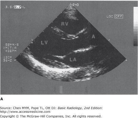
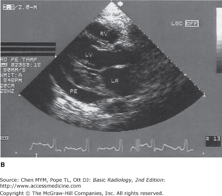
(A) Normal transthoracic echocardiogram from a healthy subject. Views are taken from the left midparasternal region through an intercostal space. The structure closest to the apex of the screen is the chest wall. The mitral valve, separating the left atrium and left ventricle, is partially open in this image from early systole. A, aorta; LA, left atrium; LV, left ventricle; RV, right ventricle. (B) Transthoracic echocardiogram, left parasternal view, from a patient with a moderate-sized posterior pericardial effusion (PE), visualized as a sonolucent space between the epicardium and pericardium. RV, right ventricle; LV, left ventricle; LA, left atrium.
Figure 3-6.

Transthoracic spectral Doppler tracing taken from an intercostal space over the cardiac apex. The Doppler sample is placed in line with the left ventricular outflow and aorta (shown in miniature echocardiogram image at top right). Velocity of flow is denoted along left edge of tracing in cm/s. The Doppler tracing shows that aortic peak velocity (a) is normal (140 cm/s). This technique can reliably assess the presence of and quantitate the severity of aortic stenosis.
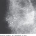
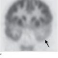
Cardiac radionuclide imaging, primarily used for the patient with suspected myocardial ischemia or infarction, requires an intravenous injection of radioactively labeled compounds that have an affinity for the myocardium. These compounds localize within the myocardium in diseased or damaged areas, and a radioactivity detector such as a gamma camera can image their distribution. These tests are most commonly used in the evaluation of patients with angina and atypical chest pain (Figure 3-7). Gallium scans are occasionally used to assess for intrinsic myocardial disease such as myocardial sarcoidosis. Positron emission tomography (PET) with 18F-FDG (18F-fluorodeoxyglucose) is a problem-solving tool that has shown promise in assessing myocardial viability in patients with known coronary artery disease and to assess for metabolically active infiltrative disease (Figure 3-8). In addition, rubidium-82 and nitrogen-13 ammonia have been used as PET agents to evaluate myocardial perfusion.
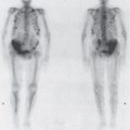
Figure 3-7.
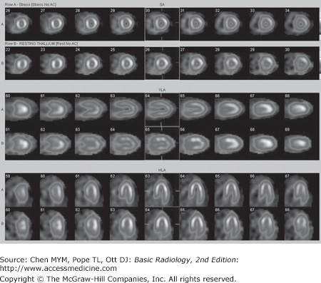
Normal myocardial stress/rest study. Stress imaging performed with technetium-99m tetrofosmin following treadmill exercise achieving target heart rate. Resting images performed using thallium-201. Homogeneous perfusion of the left ventricular cavity is seen with both stress images (top of image pairs) and rest images.
Cardiac computed tomographic angiography has undergone a revolution over the past decade. Owing to improved detectors, increased detector rows, and decreased scan times, breath-hold imaging of the heart can now be performed in many cases without pharmaceutical intervention (Figure 3-9). The major indications for cardiac CT are to evaluate the coronary arteries in subjects with indeterminate nuclear stress tests, to characterize or confirm coronary or cardiac anomalies, to assess location and patency of bypass grafts, and, in some cases, to assess for the presence of atherosclerotic disease in subjects presenting to the emergency department with atypical chest pain. The last is often performed with an extended coverage of the chest to concomitantly evaluate for pulmonary embolism and aortic dissection (triple rule-out). At the present time, some physicians also use the measurement of calcium in the coronary arteries detected at unenhanced ECG-gated CT to stratify the risk of future cardiovascular events (Figure 3-10). Contrast administration is mandatory when there are questions related to intrinsic cardiac anatomy or abnormalities of the thoracic aorta such as dissection or for evaluation of the pulmonary arteries for pulmonary embolism. For many of these applications, rapid administration of contrast is necessary (up to 4–5 mL per second), and a well-functioning large-bore (at least 18- to 20-gauge) IV catheter must be present to ensure a high-quality study.
Figure 3-9.


Normal anatomy at cardiac CT angiography. (A) Axial composite image and (B) 3D volume rendered images in right anterior oblique, left anterior oblique, and cephalad projections (from left to right). Ao, aorta; AV, aortic valve; CS, coronary sinus; Diag, diagonal branch; IVC, inferior vena cava; LA, left atrium; LAA, left atrial appendage; LAD, left anterior descending artery; LCX, left circumflex artery; LM, left main coronary artery; LIPV, left inferior pulmonary vein; LPA, left pulmonary artery; LSPV, left superior pulmonary vein; LV, left ventricle; MV, mitral valve; MPA, main pulmonary artery; RA, right atrium; RCA, right coronary artery; RIPV, right inferior pulmonary vein; RPA, right pulmonary artery; RSPV, right superior pulmonary vein; RV, right ventricle; RVOT, right ventricular outflow tract; SVC, superior vena cava.
The major drawback to CT for cardiac imaging at present is the use of ionizing radiation, which without careful management can be 4 to 5 times higher than for a standard chest CT. Fortunately, many techniques have been developed that lower radiation exposure. These include, but are not limited to, limiting scan distance, pulsing the x-rays to limit exposure during systole, prospectively gating rather than retrospectively reconstructing oversampled data, and modulating the x-ray beam based on patient size.
MR imaging has also gained rapid acceptance for cardiac evaluation, as it does not use ionizing radiation, can provide morphologic and physiologic data, and can be performed to give cine-loop images. MR cardiac imaging remains a challenge because of the inherent difficulty of simultaneously dealing with respiratory and cardiac motion, the competing needs for spatial and temporal data, and the hands-on approach to tailor the examination to the specific clinical question. Thus, MR imaging is largely a problem-solving tool, rather than a screening study. The major indications for MR imaging are congenital heart disease and suspected intracardiac masses, valvular dysfunction, pericardial disease, and aortic abnormality. From a functional standpoint, MR has the ability to asses cardiac function and motion, distinguish infarct from ischemia and help determine the advisability of revascularization (Figure 3-11), and measure flow across valves or coarctations. On the research side, MR imaging has also shown some promise in measuring the degree of damage from coronary artery atherosclerosis and evaluating the composition of atherosclerotic plaque.
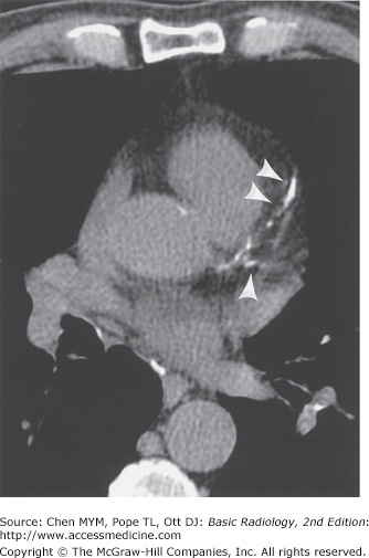
Figure 3-11.

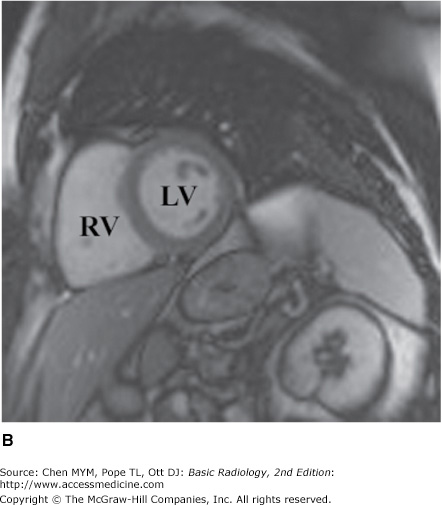
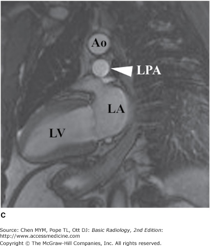

Axial (A), short-axis (B), and long-axis (C) gradient echo “white blood” MR images with normal anatomy. (D) Delayed gadolinium enhancement study in a different case reveals extensive delayed enhancement of inferior wall (arrows) indicating infarct that is not amenable to revascularization. Ao, aorta; LA, left atrium; LPA, left pulmonary artery; LV, left ventricle; RA, right atrium; RV, right ventricle.
Conventional angiography is one of the most commonly performed imaging tests for evaluating the heart and great vessels. After the introduction of a catheter into a peripheral vessel (usually, the femoral or axillary vein or artery), the angiographer, under fluoroscopic visualization, positions the catheter in the region of interest, injects contrast material to confirm the location of the catheter, and then injects larger amounts of contrast material for diagnostic purposes. This injection of contrast material can be videotaped, recorded as standard or digital radiographs, or digitally stored for later review. There are four major types of angiography: angiocardiography (heart), coronary arteriography (coronary arteries) (Figure 3-12), aortography (aorta) (Figure 3-13), and pulmonary angiography (pulmonary arteries and lungs). Techniques developed by radiologists, angiocardiography and coronary arteriography, are now almost exclusively performed by cardiologists.
Figure 3-12.


(A) Coronary arteriogram. Images were obtained from the left lateral projection with contrast injection into the left main coronary artery. The left anterior descending (L), left circumflex (CX), and first obtuse marginal (O) branches are visualized. Severe stenosis is seen in the midportion of the left anterior descending artery (arrow) in this patient, who had unstable angina pectoris. (B) Coronary arteriogram, same projection and patient as in (A), obtained 1 day later. The stenosis in the left anterior descending coronary artery (arrow) has been reduced after percutaneous balloon angioplasty.
Figure 3-13.
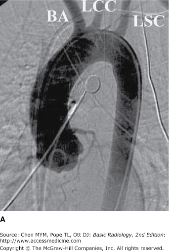

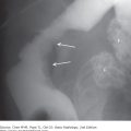
(A) Normal aortogram of transverse arch in patient suspected of having traumatic aortic injury. Note the normal origins of the brachiocephalic artery (BA), left common carotid artery (LCC), and left subclavian artery (LSC) from the arch of the aorta. (B) Aortogram in a patient with acute traumatic aortic injury. The site of injury is the focal outpouching at the insertion of ductus arteriosus (arrow).
Technique Selection
There is a wide array of imaging tests that can be used to evaluate the cardiovascular system (see Table 3-1). After a thorough history and physical examination, the initial screening study should always be a chest radiograph. Ideally, the PA and lateral views should be obtained with maximum inspiration. This study gives important information about the cardiac contour and the status of the lungs, and it is a good examination for excluding disorders that would require immediate treatment, such as pneumothorax. Furthermore, evaluation of the chest radiograph can often lead to a specific diagnosis and treatment, such as in congestive heart failure, or can help determine the need for another imaging study.
Depending on the history and physical examination findings, echocardiography, nuclear cardiac imaging, CT, MR, or conventional coronary angiography may follow. Echocardiography is a good screening test to assess cardiac and great-vessel valvular motion and structural abnormalities, cardiac chamber morphology, and flow. Angiography delineates the structural status of the coronary arteries and can give information on blood flow through the cardiac chambers, valves, and proximal great vessels, mainly in patients with suspected atherosclerosis. It is also used to guide interventions such as stent placement in the coronary arteries. Because of its inherent risks, coronary arteriography is usually reserved for patients with signs and symptoms of myocardial ischemia or infarction on the basis either of history or of results of electrocardiography, echocardiography, or radionuclide myocardial imaging.
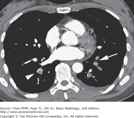
In patients with suspected pulmonary emboli, helical CT is the most appropriate test in the setting of an abnormal chest x-ray (Figure 3-14). The ventilation-perfusion (V/Q) scan can be performed if the chest radiograph is normal and is also the preferred examination in young females because of the radiation dose to the breast by CT. Both of these tests can confirm the clinically suspected diagnosis of pulmonary embolic disease and often provide a useful “map” of the most suspicious regions of the lung for the angiographer if an angiogram is required for the definitive diagnosis of pulmonary embolism. CT can also detect important alternative diagnoses not detected by either V/Q scan or pulmonary angiography. More frequently, patients with atypical chest pain are being referred for the triple rule-out examination. This test is not appropriate for patients with clear signs or symptoms of myocardial ischemia and should be reserved for intermediate- to low-risk patients with a nondiagnostic ECG and negative first set of troponins.
Echocardiography, MR imaging, or CT or cardiac angiography may be selected for patients with suspected congenital heart disease. The advantages of MR imaging in this setting is that it is noninvasive, generally needs no contrast material administration, and uses no ionizing radiation, an important consideration in the pediatric patient. For these reasons, MR imaging has become the preferred imaging test in the pediatric population. As dose reduction techniques have improved, the use of CT for congenital heart disease has also increased.
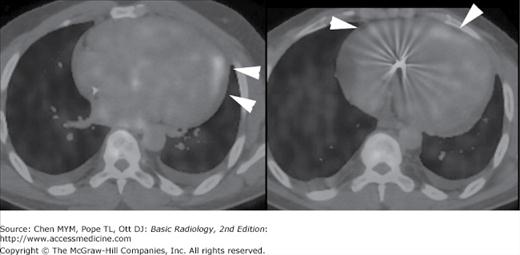
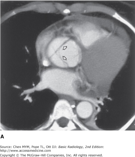
Suspected aortic dissection (either atherosclerotic or traumatic in origin) can be evaluated by helical CT, TEE, aortography, or MR imaging. Helical CT is the imaging modality of choice for acute dissection because of its accuracy and availability (Figure 3-15). With multislice technology, CT angiography can provide images in multiple planes to show the relation of the dissection to key branch vessels. TEE has the advantages of being quick and noninvasive, and the examination can be performed expediently at the bedside. MR imaging is noninvasive, uses no ionizing radiation, is less operator-dependent, and can be performed in multiple planes. It is limited by availability and imaging time and because it cannot be used in patients with certain implanted devices, particularly pacemakers. Angiography has mostly been relegated to minimally invasive treatments such as stent-graft placement. Because survival rates often depend on early surgical intervention, availability and timeliness of the examinations is important.

In patients whose chest radiographs suggest intrinsic pulmonary or mediastinal processes, a standard chest CT is currently the preferred modality. The use of contrast depends on the indication, the preference of the radiologist, and any possible contraindications to administration of intravenous contrast for individual patients.
Finally, regardless of the situation, it is reasonable for the clinician and radiologist to decide together which imaging tests are most appropriate. In many instances, the choice of the next most efficacious and least costly imaging examination is not always clear-cut. In fact, in some circumstances, it is not necessary to perform another test because of the limited potential yield from the examination or because there is no adequate therapy for the suspected abnormality. It is hoped that future recommendations for test selection will be determined by well-designed prospective unbiased outcome studies comparing all of these modalities in various clinical scenarios. In the meantime, a commonsense approach, taking into consideration the history and physical examination findings, the information gleaned from the conventional radiograph, and the potential yield from the array of other available imaging tests, is the most appropriate. In all instances, communication between the clinician and radiologist is critical for the best patient care.
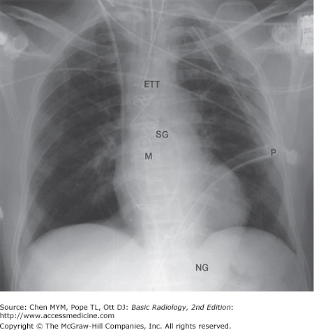
In clinical hospital practice, particularly in the ICU setting, a variety of catheters and tubes are used to monitor various parameters in patients (Figure 3-16). The student should be familiar with the normal routes and positions of these devices, as well as inappropriate positions and complications. Table 3-3 lists the most common monitoring devices.
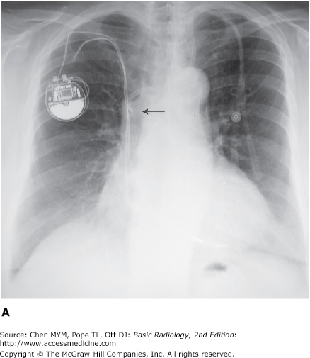
The basic venous anatomy of the upper mediastinum should be reviewed and kept in mind when evaluating catheter placement. The most common routes of catheter insertion in the chest include the internal jugular and subclavian veins. Radiographs obtained after insertion show the catheter following the course of either the internal jugular or subclavian vein and passing through the brachiocephalic vein. It then curves gently downward to terminate in the superior vena cava proximal to the right atrium (Figure 3-17). One normal variation of venous anatomy is the persistent left superior vena cava. In this situation the catheter descends down the left mediastinum terminating in the left SVC. The left SVC ultimately drains into the coronary sinus, which then enters the right atrium.

Intrathoracic central venous catheters are used mainly for monitoring central venous pressure (CVP), maintaining proper nutrition, delivering medication, and hemodialysis. It is standard practice to request a chest radiograph after catheter placement to verify its location (Figure 3-18) and to check for potential complications, such as pneumothorax (Figure 3-19) or hemothorax. Measurement of CVP is optimally obtained when the tip of the catheter is proximal to the right atrium and distal to the most proximal valves of the large veins. A catheter tip proximal to the veins gives an inaccurate reading of CVP, and a tip too close to the right atrium may cause arrhythmias from irritation of the right atrial myocardium. The reason for catheter insertion is critical for identifying its appropriate position. If it has been placed just for fluids and/or medications, a termination in the brachiocephalic vein is satisfactory. Conversely, a plasmapheresis catheter should never be located in the right atrium because of the risk of complications. More frequently, central venous catheters are being placed centrally via a peripheral vein. These catheters have minimal risk, can remain in place for longer periods of time without being exchanged, and are primarily used for the delivery of fluids and long-term antibiotics.
Figure 3-18.

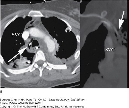
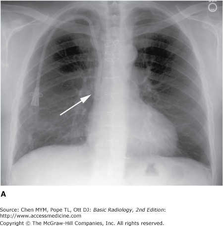
Malposition of central venous catheter. (A) Portable frontal radiograph reveals central venous catheter overlying the expected region of superior vena cava (arrow). Because of lack of blood return, CT with contrast was obtained. Note also the widening of the right paratracheal stripe (*). (B) Axial and curved planar reformation reveal catheter has perforated the posterior wall of the superior vena cava with the tip residing in the mediastinum (arrows). SVC, superior vena cava.

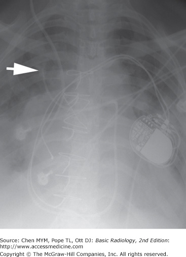
The major potential complications from catheter placement are outlined in Table 3-4. A malpositioned central venous catheter may result in inaccurate CVP measurement, thrombosis, catheter knotting, and infusion of substances into the mediastinum or pleura. Catheter tips against the wall of the SVC may erode into the mediastinum or may extend retrograde into tributary veins, particularly the azygous vein (Figure 3-20).
Malposition |
Catheter knotting/fragmentation |
Pneumothorax |
Vascular injury |
Thrombosis (venous) |
Infarction (pulmonary arterial) |
Infection/septic emboli/endocarditis |
Air embolism |
Cardiac arrhythmias |
Fistulas |
Arteriovenous |
Venobronchial |
Arteriobronchial |

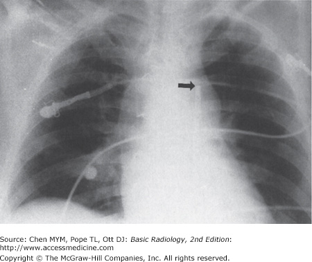
Flow-directed arterial catheters are also regularly used in cardiac and ICU patients to monitor cardiac output. The most common flow-directed catheter is the Swan-Ganz (SG) catheter (see Figure 3-16). It is usually inserted percutaneously into the left or right subclavian vein and threaded through the brachiocephalic vein, superior vena cava, right atrium, tricuspid valve, right ventricle, pulmonic valve, and directed out into the main pulmonary artery. Usually terminating in the right or left pulmonary arteries, the SG tip should be distal to the pulmonary valve and proximal to the smaller pulmonary arterial vessels so it will not cause occlusion and, potentially, thrombosis. A simple rule of thumb is that the catheter should not extend past the mediastinal borders. It may then be intermittently “wedged” into a distal pulmonary artery branch to obtain a pulmonary capillary wedge pressure.
Complications of SG catheter placement are similar to those with other central venous catheters. The tip may be positioned in a number of inappropriate vessels or locations, and a chest radiograph should be obtained after catheter insertion to confirm its position (Figure 3-21). Introduction of any catheter into the subclavian vein, because of its close proximity to the lung apex, can cause pneumothorax (see Figure 3-19). A catheter tip position in the right ventricle can lead to ventricular arrhythmias, and leaving the catheter tip too distal may result in a pulmonary artery pseudoaneurysm or pulmonary infarct.
An intraaortic counterpulsation balloon pump (IABP) is occasionally used in patients with cardiogenic shock. This catheter measures approximately 26 cm in length and is surrounded by a balloon, which inflates with helium or carbon dioxide gas during diastole and deflates during systole. Deflation during systole decreases afterload and results in diminished left ventricular work and oxygen requirements, while the inflation of the balloon during diastole increases cardiac pressure to help ensure adequate perfusion of the coronary arteries. The catheter, introduced percutaneously into the thoracic aorta via the common femoral artery or placed into the ascending aorta at the time of surgery, should be positioned so that its tip is just distal to the origin of the left subclavian artery. The tip of the catheter has a small radiopaque marker so that this position can be ascertained on the chest radiograph (Figure 3-22). The major complications of the IAPB result from positioning of its tip proximal to the left subclavian artery, which may cause occlusion of the left subclavian vessel orifice, cerebral artery embolization, or aortic tear. If positioned too low, the balloon may occlude the celiac, superior mesenteric, and renal arteries.
Unipolar or bipolar pacemakers are most common and are usually implanted in the chest wall with leads inserted into the subclavian vein. The unipolar pacemaker tip is normally situated at the apex of the right ventricle. The bipolar pacemaker has a proximal lead that terminates in the right atrium and a distal lead that terminates within the right ventricle (similar to the unipolar pacemaker position). Biventricular pacemakers have a third lead present in the coronary sinus, appearing superior to the right ventricular lead (Figure 3-23
Related posts:

Stay updated, free articles. Join our Telegram channel

Full access? Get Clinical Tree


