Techniques and Normal Anatomy
Conventional radiography is the most commonly used imaging technique to evaluate the joints of the musculoskeletal system. This technique should always be the first imaging study performed in a patient suspected of having joint problems. Radiography has the following important advantages: It is almost universally available, is relatively inexpensive compared to other imaging studies and delivers only a small radiation dose to the patient. When possible, orthogonal projections should be obtained, meaning two images of the joint that are perpendicular to each other (usually a frontal projection in either in the anteroposterior [AP] or posteroanterior [PA] directions and a lateral). In some instances oblique images may also be obtained, depending on the preferences of the referring physician or radiologist or the clinical situation. In certain instances it may also be important to obtain images of the joint proximal and distal to the injury. Examples of this include the forearm and lower leg (paired bones), as the joints proximal and distal are often injured. Because conventional radiography uses ionizing radiation, it should be used judiciously, especially in pediatric patients and pregnant women.
Historically, radiographic images were printed on film. However, with widespread adoption of PACS (picture archiving and communications system), images can be electronically processed and viewed on computer work screens. These images then can be transmitted anywhere electronically via the Internet.
Conventional tomography is mentioned mainly for historical interest. High radiation dose, relatively poor image resolution, and imaging that is only possible in one plane were its major disadvantages. The technique has been almost totally replaced by other imaging tests, especially computed tomographic (CT) and magnetic resonance (MR) imaging. Orthopantograms are one of the few remaining vestiges of this imaging technique.
Arthrography is a technique in which contrast is injected into the joint using fluoroscopic guidance. The joint is then imaged using radiography, CT, or MR imaging or a combination of these techniques. The injected contrast may be an iodine-containing water-soluble compound (eg, Conray), subsequently imaged with radiography or CT (Figure 7-1). Alternatively, a paramagnetic compound (eg, gadolinium pentazocine) may be injected and imaged with MRI. MR arthrographic images of the joint may also be performed after intravenous injection of the paramagnetic contrast agent, although this technique does not distend the joint, and thereby is not used commonly today. MR arthrography is mainly used to evaluate the labrum of the hip or glenohumeral joint (Figure 7-2) but is also useful in the evaluation of the structures of the wrist and elbow joints. CT arthrography, and less commonly conventional arthrography can be useful in patients who cannot undergo, or have contraindications to, MR imaging (Figure 7-3).
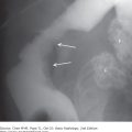
Figure 7-1.
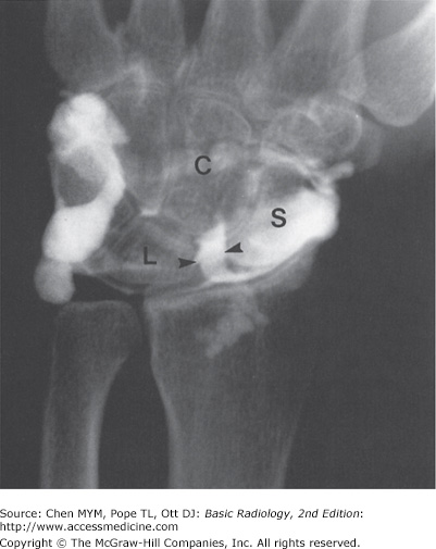
Contrast arthrogram with plain radiograph: AP wrist arthrogram view obtained after injection of contrast material into the radiocarpal joint shows contrast material passing through the scaphoid (S) and lunate (L) space from the radiocarpal joint into the mid-carpal joint (arrowheads). This indicates a tear in the scapholunate ligament (C, capitate bone).
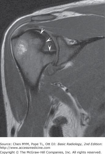
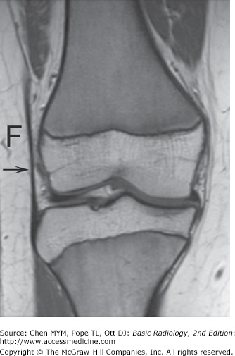
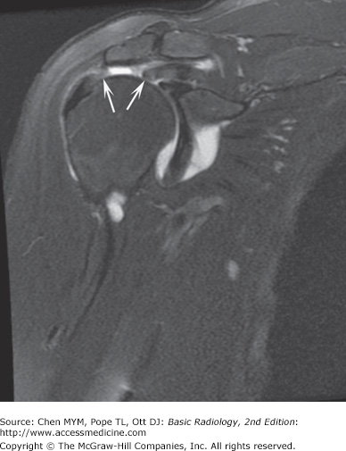
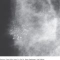
Figure 7-2.
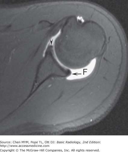
Axial T1 weighted, fat-saturated MR arthrogram of the shoulder shows marked joint distention with contrast (F) and the normal glenoid labrum anteriorly (arrowhead) and posteriorly (arrow). MR arthrography is used mainly to evaluate the shoulder for tears of the labrum and symptoms of instability.
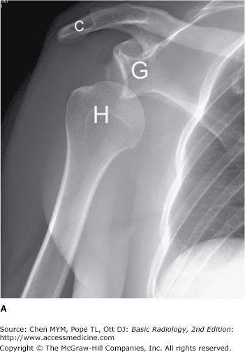
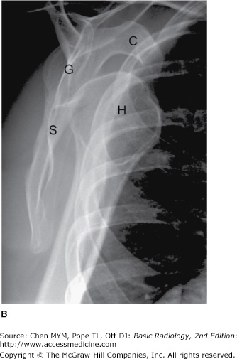
Figure 7-3.
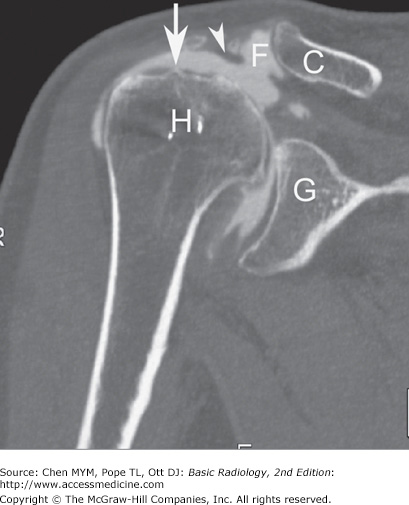
CT arthrography. Coronal reformatted CT image of the shoulder after fluoroscopically guided, intraarticular contrast administration. CT arthrography is often used when the patient has contraindications to MR imaging. The image reveals a full-thickness rotator cuff tear with contrast in the subacromial-subdeltoid bursa (arrow) and contrast interposed between the acromioclavicular joint, the CT “geyser sign” (arrowhead). H, humeral head; G, glenoid; C, distal clavicle; F, contrast.
Computed tomography (CT), a technique that makes individual axial (transverse) slices of the patient, uses the same ionizing radiation as in conventional radiography. CT technique has been vastly improved in the past decade. The development of spiral or helical CT has major advantages over earlier CT technology. With the spiral CT technique, axial (transverse) images are acquired much more rapidly with dramatic decreases in radiation dose. For instance, a CT of the chest, abdomen, and pelvis can be performed in about 16 seconds. CT data is stored in three-dimensional packets that can then be reconstructed and displayed in almost any other plane. The most common images reconstructed from the axial plane are the sagittal and coronal planes (Figure 7-4).
Figure 7-4.
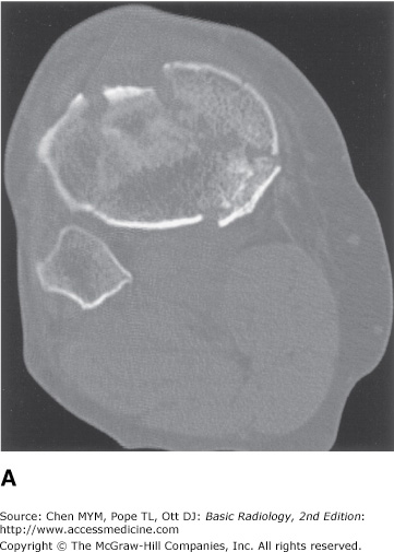
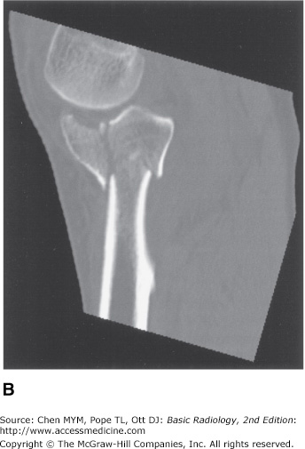
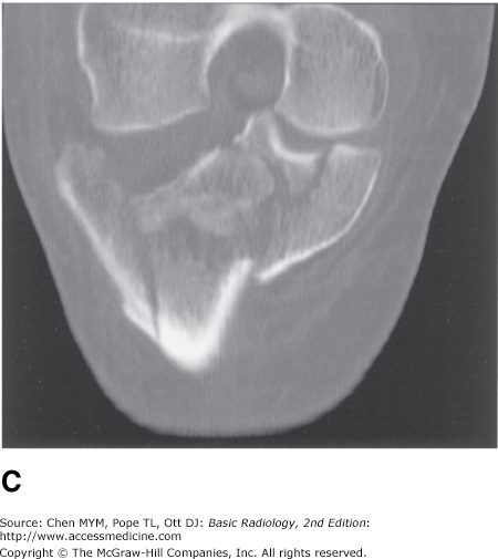
(A) Axial CT scan showing a comminuted fracture of the proximal tibia. (B) Sagittal reconstruction of the axial data, again showing the comminuted tibial fracture. (C) Coronal reconstructed CT image showing the markedly comminuted fracture of the proximal tibia with extension into the joint. Current CT applications can be used to reconstruct data in multiple planes.
MR imaging has revolutionized the imaging evaluation of almost all body areas, but particularly those of the central nervous system and musculoskeletal system. It has tremendous advantages over other imaging modalities in the evaluation of joints because of its excellent soft-tissue contrast, high resolution, and ability to image in every plane. This technique may show pathophysiologic events even before they are seen on conventional radiographs or CT, for example, revealing the early changes of avascular necrosis (Figure 7-5). Because of its exquisite soft-tissue contrast, MR imaging allows radiologists to visualize subtle differences in soft tissues that had never before been seen with other imaging modalities. For example, the subtle contrast between fat and muscle seen on a conventional radiographs or CT is dramatically highlighted with the use of MR imaging because of their very different chemical compositions (Figure 7-6). MR imaging can also depict subtle changes within the bone marrow cavity, an area difficult to evaluate with conventional radiography or CT. Therefore, MR imaging is a tremendous aid to preoperative evaluation of any patient who has unexplained joint pain or who has had joint trauma. One of the major disadvantages of MR imaging is that some patients with claustrophobia cannot tolerate the prolonged imaging time in the small bore of the magnet. In addition, patients with metallic foreign bodies or non-MR-compatible medical devices or hardware have contraindications to MR imaging. Concerns include motion of the objects, abnormal electrical arcs resulting in burns, and device malfunction.
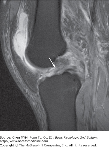
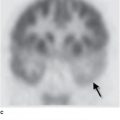
Figure 7-5.
Coronal, T2 weighted fat-saturated MR image of avascular necrosis of the humeral head. MR image of the shoulder reveals an area of bone infarct adjacent to the articular surface of the humeral head (arrowheads). MR imaging can show this abnormality much earlier than conventional radiography.
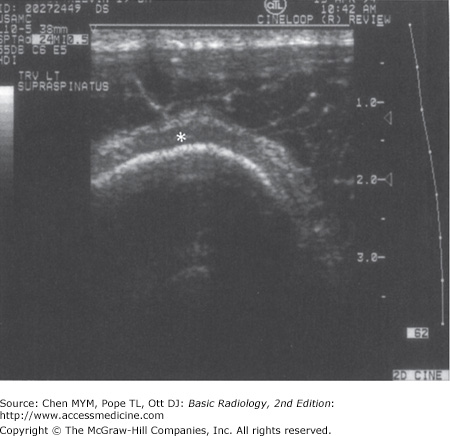
Ultrasonography, first developed for use in World War II for detection of submarines, was adopted after the war for use in medical imaging. High-frequency transmission of sound can be used to evaluate the soft tissues, tendons, ligaments, and even the cartilage of the joint. The ultrasound waves cannot be transmitted through cortical bone, so the intramedullary cavity cannot be imaged with this technique. Ultrasound is used more extensively in Europe than in the United States; however, there is increasing interest in this modality within the United States. The main drawback of this modality is that it is highly user-dependent, relying heavily on the skill of the operator (Figure 7-7).
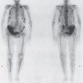
Radionuclide imaging uses radioactive materials that are injected intravenously and then localize in regions of abnormally increased blood flow (hyperemia), increased osteoblastic activity, or heightened metabolic activity. The major uses of bone scanning are in patients suspected of having metastatic disease or infection. This modality is very sensitive, but it has limited specificity, and often the findings must be correlated with other imaging modalities, especially radiography. Therefore, this technique is not usually used as a primary modality for the evaluation of joint disease.
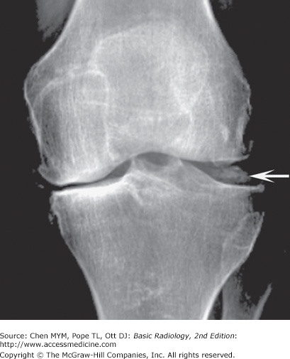
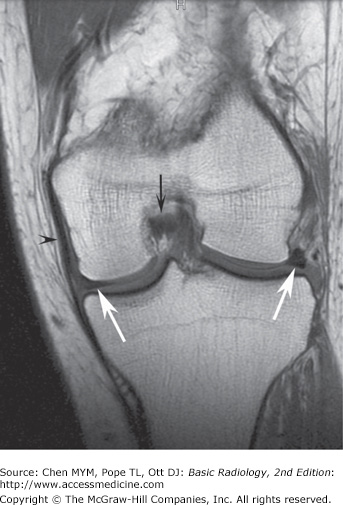
The typical normal synovial joint consists of at least two articulating bones enclosed in a synovium-lined joint capsule. The apposing bony surfaces are covered by smooth articular cartilage (hyaline cartilage). On radiographs, the normal joint has a separation between the adjacent bones representing the region occupied by the hyaline or articular cartilage, menisci, and joint fluid (the so-called articular space) depending on which joint is imaged. Because of the limited soft-tissue contrast of the technique, these structures are not normally depicted on radiographs unless they are calcified (Figure 7-8). However, MR imaging exquisitely shows the components of the normal joint (Figure 7-9).
The clinical signs and symptoms of joint disease are manifestations of abnormal function such as reduced mobility, hypermobility, and pain. Altered function may be due to pain, discomfort, apprehension, or instability. The wide range of joint abnormalities is summarized below, and many of these processes are discussed in the exercises. Any of these signs may occur in isolation or in combination with any others.
Radiographically, joint disease may be diagnosed by any of the following:
Incongruity of the articulating bone as is seen with dislocations, for example, traumatic dislocation or dislocations caused by arthropathies such as lupus arthritis or rheumatoid arthritis.
Irregularity of articulating bone surfaces and margins, as in erosions (eg, in psoriasis or gout).
Increased density or sclerosis of articulating bone surface (also called “eburnation”), as in osteoarthritis.
Bony outgrowths (proliferation) at bone ends, known as osteophytes.
Diffuse decrease of bone density adjacent to articular surfaces, described as juxtaarticular or periarticular osteopenia (eg, rheumatoid arthritis, tuberculous arthritis).
Focal, well-defined, spherical lucencies within subchondral bone, known as subchondral cysts or geodes (eg, osteoarthritis, rheumatoid arthritis).
Loss of articular joint space from articular cartilage destruction (eg, septic arthritis, osteoarthritis).
Accumulation of excess joint fluid within the joint (joint effusion). Excess joint fluid is a common manifestation of joint disorders. The fluid may be synovial fluid, blood, or even pus, depending on the etiology of the joint disease.
Calcification of articular (hyaline) cartilage or fibrocartilage (chondrocalcinosis), or intraarticular soft-tissue calcification such as that seen in scleroderma or polymyositis or dermatomyositis.
Synovial proliferation or abnormal increase in the synovial lining, such as that seen with pigmented villonodular synovitis (PVNS).
Technique Selection
Radiography should always be the initial imaging test to evaluate the joints and should be obtained after the patient has had a thorough history and physical examination and there is a clear indication to obtain the study. Various projections may be used depending on the clinical indication or the situation, but at least two orthogonal projections should be obtained. Often radiographs alone will confirm or refute the clinical diagnosis. In many instances, however, it may be necessary to use more sophisticated imaging techniques to clarify the radiographic findings or to further evaluate depending on the clinical scenario. The following paragraphs discuss the selection of the imaging techniques in a few common clinical scenarios.
Conventional radiographs should be the initial modality of choice when confronted with a possible congenital anomaly or pediatric joint abnormality, or in a child presenting with a limp.
Given that the joint structures are not well mineralized in children, further evaluation of the joint with ultrasonography or MR imaging is often required to make a definitive diagnosis, as these modalities have superior soft-tissue resolution. If MR imaging facilities are not available, congenital abnormalities can be investigated with a combination of conventional radiography, ultrasonography, and CT.
In acute trauma, the conventional radiograph remains the mainstay of the initial imaging assessment. If fractures are identified, additional imaging will depend on the needs of the clinician or sub-specialist physician as dictated by the clinical situation. Generally, fractures that extend into the joint surface (intraarticular fractures) are treated with greater concern because of the importance of reestablishing the integrity of the joint. Intraarticular fractures are frequently treated by operative reduction and internal fixation, especially if the fracture fragments are severely displaced. CT examination of the injured limb and joints is used preoperatively for surgical planning and postoperatively to assess the results of surgical intervention. The advantages of CT are that it enables precise assessment of joint reconstitution and also identifies any intraarticular bone fragments or entrapped tendons that could interfere with proper reduction and healing (see Figure 7-4).
Conventional radiographs are used initially to determine the integrity of the joint. If the joint is normal and there is a persistent clinical suspicion of injury, MR imaging should be employed because of its superior soft-tissue contrast and resolution. It is, therefore, particularly suited for investigation of the intraarticular and periarticular soft-tissue structures and cartilage (see Figures 7-5, 7-6).
Likewise, if the initial conventional radiographs are normal, MR imaging is the next modality of choice in the patient with a painful joint. MR imaging may detect evidence of a small joint effusion, inflamed synovium, and subtle erosions that could suggest the diagnosis of an inflammatory arthropathy or a septic joint. Percutaneous joint aspiration of synovial fluid, often fluoroscopically guided, may result in confirmation of infection or yield abnormal crystal deposits within the joint, such as with gout.
Exercise 7-1. Congenital Joint Disorders
bilateral developmental dysplasia of the hips (DDH).
Legg-Calvé-Perthes disease.
proximal focal femoral deficiency syndrome (PFFDS).
neuropathic joint disease.
tomography of both hips.
MR imaging of the hips.
radionuclide bone scan of the pelvis.
CT of the hips.
7-3. The patient in Case 7-3, whose film is shown in Figure 7-12, most likely suffers from what condition?
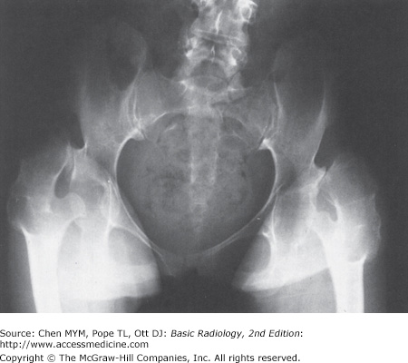
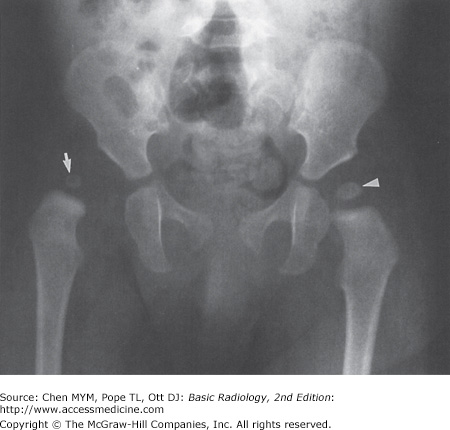
7-1. Both hips in the patient in this case (Figure 7-10) are abnormal. The femoral heads and necks are malformed and dislocated from the acetabula fossae superiorly. The acetabulae are also malformed and oriented more vertically than normal. The patient had bilateral congenital dislocation of the hips that had been ignored by her parents (A is the correct answer to Question 7-1). This diagnosis should have been made at birth or shortly thereafter so that corrective therapy could have been instituted.
7-2. In this case (Figure 7-11), the capital femoral epiphysis on the right (arrow) is laterally displaced and smaller than the left epiphysis (arrowhead). The acetabular fossa on the right side is also malformed and more vertical than the one on the left. The normal development of the acetabulum is dependent on a normally located femoral head, and this is the explanation for this abnormality. These findings are the classical radiographic features of developmental dysplasia of the hip (DDH). When this finding is encountered, MR imaging is the next most appropriate imaging test (B is the correct answer to Question 7-2).
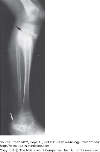
7-3. In this case (Figure 7-12), the calcaneus is deformed (white arrow). The talus is poorly visualized because of its complete dislocation from its normal position below the tibia, and there are subluxations at the tibiotalar, talocalcaneal, and talonavicular joints. There is overall frank disorganization of this ankle joint, and clinically there was diffuse soft-tissue swelling around the ankle (not appreciated on this lateral film). There is also a metaphyseal fracture of the proximal tibia with exuberant periosteal/callus formation (black arrow). All of these findings in this patient are caused by chronic repetitive trauma in a patient with congenital insensitivity to pain (D is the correct answer to Question 7-3).
Congenital joint disorders are uncommonly encountered, but they should be diagnosed as early as possible after birth because delayed diagnosis complicates management. Some of the more common congenital joint disorders include:
Congenital dislocation of the hips
Arthrogryposis multiplex congenita
Congenital insensitivity to pain (asymbolia)
Congenital hip dislocation is actually a bone dysplasia manifesting as a joint disorder. The femoral head is dysplastic and does not provide adequate stimulation for proper development of the acetabulum. Usually, the femoral head is displaced laterally out of an unusually shallow (ie, more vertically oriented) acetabulum (Figure 7-11). Once the diagnosis of DDH is confirmed, treatment should begin at birth or in the perinatal period to minimize complications.
Historically, hip arthrograms were used to define the location of the femoral head in the neonate because the structure is cartilaginous at birth and therefore radiolucent. Ultrasonography is an excellent test to assist in the diagnosis of DDH in utero and in the neonatal period because it requires no ionizing radiation. However, the interpretation of ultrasound is observer dependent, and the diagnosis and characterization of DDH can be difficult at times. MR imaging can show the soft-tissue and osseous structures, as well as the articular cartilage, and is currently the modality of choice in the evaluation of DDH. If patients are not treated or are incompletely treated, they will eventually develop secondary, premature osteoarthritis. MR imaging offers limited diagnostic value over conventional radiographs in late-stage disease.
Proximal focal femoral deficiency (PFFD) is a disease of uncertain etiology that is characterized by congenital absence of a segment or all of the proximal third of the femur. The incidence is higher in children of diabetic mothers, and there is also an association with congenital hip dysplasia. MR imaging is also the imaging modality of choice in evaluating children with these disorders.
Arthrogryposis multiplex congenita is a noninheritable congenital disease of uncertain etiology characterized by multiple joint contractures. It is believed to be due to neuromuscular events occurring in utero. The joints of the lower limb are almost invariably affected. There may be other associated extraskeletal congenital anomalies.
A neuropathic joint is caused by chronic repetitive trauma in the setting of impaired or absent sensation. The characteristic features of neuropathic joint include soft-tissue swelling, fragmentation of the bony structures, and general disorganization of the joint. Joint effusion is often present. The more common causes of neuropathic joints in the lower extremities include diabetes mellitus and tabes dorsalis (neurosyphilis). Asymbolia or congenital insensitivity to pain, as exhibited in Case 7-3 (Figure 7-12), is a group of uncommon congenital disorders in which there is a variable degree of loss of pain sensation and is an unusual cause of neuropathic joints. Patients with asymbolia almost always acquire deformities of the extremities after repeated trauma. This diagnosis should be considered in the young patient with multiple healing fractures with soft-tissue swelling and joint disorganization in whom nonaccidental trauma has been excluded.
Exercise 7-2. Joint Trauma
lunate dislocation.
perilunate dislocation.
transcaphoid fracture-dislocation.
distal radius fracture.
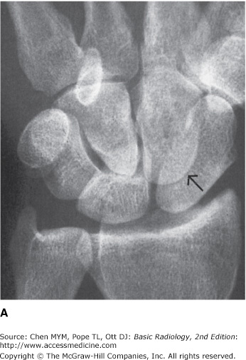
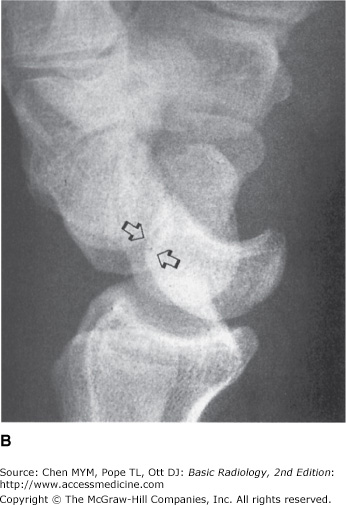
7-4. In the frontal projection (Figure 7-13 A), there is disorganization of the carpal arcs. The capitate is no longer articulating with the lunate and partly overlaps the scaphoid (arrow). The scaphoid is elongated on this view but not fractured. On the lateral projection (Figure 7-13 B) the lunate is still in line with the distal radius, but the capitate has been dislocated dorsally (open arrows). Therefore, the patient has a dorsal perilunate dislocation (B is the correct answer to Question 7-4).
Related posts:
Stay updated, free articles. Join our Telegram channel

Full access? Get Clinical Tree


