Digital Breast Tomosynthesis
As described in Chapter 27, Digital Mammography, the development of full-field digital detectors for x-ray imaging of the breast has opened new opportunities for breast cancer detection and diagnosis that were not possible with film/screen technology. Digital detectors permit the definition of an image using nothing but digits to identify the row number, column number, and a number indicating the amount of energy deposited at every pixel in the detector (Fig. 28-1). By having an image that can be evaluated by a computer, major opportunities arise to improve x-ray imaging of the breast. Digital breast tomosynthesis (DBT) is a major advance made possible by the availability of digital detectors.
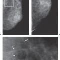
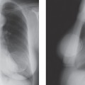
One of the major problems with conventional two-view, two-dimensional (2D) mammography is the fact that the normal breast tissues can be superimposed on a breast lesion and get in the way by obscuring a small cancer. This is most evident when comparing the clarity with which a cancer is visible on a specimen radiograph to the difficulty seeing it while it was still in the breast (Fig. 28-2). Of course, the geometry of the imaging of the specimen, with the object immediately against the detector, is superior to imaging the lesion when it is displaced from the detector by intervening breast tissue, but it is also clear that the lesion in the specimen is much better seen because of the elimination of the normal structures of the breast tissues that are projected on top of the projection of the lesion and obscuring it. This “structure noise” is a major impediment to the detection and diagnosis of many breast cancers.
In 1971, Miller et al reported on a technique to help reduce the problem of overlapping normal structures. They took a relatively small number of projections using an x-ray beam coming from different angles (1) and used those images to “synthesize” slices though the tissues. The approach worked in the following fashion. The projections of structures onto a detector shift less between images obtained from different angles if they are closer to the detector than if they are further away from the detector (Fig. 28-3). This is the well-known phenomenon of parallax shift. Based on the differing parallax shifts of structures in different planes, they showed that they could line up the images and add them together so that only the structures that were in the same plane were perfectly aligned, reinforcing one another, while structures in other planes were out of alignment. The aligned structures in the same plane were reinforced and as a result much more visible, while those that were out of alignment were harder to see because they were misaligned. The structures in one plane could be sharply defined, while those in the other planes were essentially eliminated. By shifting the images and adding them again in a programmed fashion, every plane through the structure could be “synthesized” in sharp registration, while those out of the plane were made less conspicuous by misregistration. This technique, now known as “shift and add,” effectively blurred the out-of-plane structures so that only the plane of interest was visible in sharp detail. In this way the images could be “shifted” and “added” to align and synthesize any and all planes parallel to the detector.
Unlike conventional linear or hypocycloidal tomography, where the x-ray source and detector need to be moved for each slice and a full exposure is required for each slice, tomosynthesis requires a relatively few projections, yet permits all planes through the object to be “synthesized” from these few images. We recognized the potential for this technique for imaging the breast in the late 1970s, but the technology to make it practical did not exist (digital detectors and high-speed computers). Since registration was critical and complex, an electronic detector was needed so that the images could be “shifted and added” using a computer. Unfortunately, there was no detector available in the 1970s that had sufficient resolution to develop this approach for x-ray imaging of the breast. I brought the idea of tomosynthesis to the attention of our physicist, Loren Niklason, when he joined MGH Radiology and the Breast Imaging Division, and he agreed that we should explore this for breast imaging. At the start of the 1990s, with the help of our Director of Breast Imaging Research, Richard Moore,
we realized that the full-field digital detector that was under development by General Electric was suited for use in a prototype tomosynthesis system for breast imaging. Dr. Niklason, PhD, Laura Niklason, MD, and Brad Christian, PhD, developed the physics and mathematics to make it practical for mammography, and we invented the technique for imaging the whole breast. Using phantom material and mastectomy specimens we confirmed that high-resolution x-ray tomography could be accomplished (2). There was initial resistance from General Electric to support tomosynthesis development, but they agreed to build the first prototype whole-breast unit when we received support from a grant from the Department of Defense (3). With input and guidance from Richard Moore and Dr. Niklason, General Electric constructed a DBT prototype unit that underwent clinical trials at MGH.
we realized that the full-field digital detector that was under development by General Electric was suited for use in a prototype tomosynthesis system for breast imaging. Dr. Niklason, PhD, Laura Niklason, MD, and Brad Christian, PhD, developed the physics and mathematics to make it practical for mammography, and we invented the technique for imaging the whole breast. Using phantom material and mastectomy specimens we confirmed that high-resolution x-ray tomography could be accomplished (2). There was initial resistance from General Electric to support tomosynthesis development, but they agreed to build the first prototype whole-breast unit when we received support from a grant from the Department of Defense (3). With input and guidance from Richard Moore and Dr. Niklason, General Electric constructed a DBT prototype unit that underwent clinical trials at MGH.
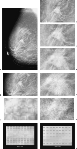 Figure 28-1 In this series of 10 images, progressive zoom is applied. As the image is enlarged the individual pixels can be seen, and ultimately the pixels and the value of the energy detected at each pixel are demonstrated (I,J). |
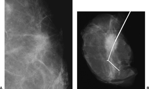 Figure 28-2 Lesions are more clearly seen when the structure noise of the breast is removed. Even when surrounded by fat, the breast cancer is difficult to see on the enlarged image from a standard mammogram (A). Once it has been removed from the breast and the normal tissue structures are out of the way, as seen on this specimen radiograph (B), its morphologic characteristics are clearly evident. |
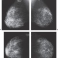
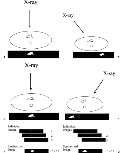 Figure 28-3 Tomosynthesis allows the “synthesis” of innumerable slices through the breast from a relatively small number of projection images. In a standard 2D image, all of the structures from one side of the breast to the other superimpose, obscuring the details (A). When images are taken from differing angles (B–E) structures in a plane closer to the detector appear to move a shorter distance than those further away (parallax shift). By electronically lining up the images so that only structures in the plane of interest perfectly align, objects out of the plane will misregister and be inconspicuous, while those in the plane will be reinforced and become more apparent (F). By shifting the images (G) and adding them again, structures in the next plane are reinforced above those out of the plane. This can be done for all planes through the breast. |
The First “Whole Breast” Digital Breast Tomosynthesis System
The prototype MGH/GE DBT system was built around the General Electric Senovision 2000 digital mammography detector system. The detector was uncoupled from the x-ray tube so that the tube could be motorized and could move independently while the compression/detector system remained stationary. With the breast held in position in the standard compression system, the x-ray tube could be moved through an arc of 50 degrees in 7 seconds. The system stopped 11 times during the 7 seconds and obtained a mammographic image of the entire breast each time it stopped. Since the synthesized images were to be a compilation of all 11 of the projection images, each of the 11 projection images was made using a fraction of the total dose of a conventional mammography system. Thus, the total dose for the 11 images was approximately 1.50 times the dose of a single MLO conventional 2D mammogram (50% more than a single, conventional, mammography image) and only 75% of the dose used for a standard two-view conventional screening mammographic study.
Once acquired, the projection images can be used to synthesize slices though the breast using the “shift and add” approach. The standard filtered back-projection processing used for CT scanning can also be used to produce synthesized images. Filtered back-projection essentially takes the
images produced at the detector and projects the x-rays backwards as they pass through the structures to form the image. Since the x-rays come from multiple directions, back-projecting them along their trajectory can be used to determine the attenuation and location of structures through which the x-ray beams passed to form the multiple projection images (Fig. 28-4).
images produced at the detector and projects the x-rays backwards as they pass through the structures to form the image. Since the x-rays come from multiple directions, back-projecting them along their trajectory can be used to determine the attenuation and location of structures through which the x-ray beams passed to form the multiple projection images (Fig. 28-4).
The “shift and add” approach to image reconstruction produces numerous artifacts on the images, since every projection image is included in every synthesized image. Filtered back-projection can increase the noise and is not optimized for demonstrating masses. To reduce these artifacts and produce high quality slices, Tao Wu, PhD (4), developed an algorithm to synthesize the slices that greatly reduces artifacts. This approach uses a maximum likelihood iterative approach. The computer makes successive models of the breast tissues. It compares how the projection images made through the model compare with the actual images, and then adjusts the model to get closer to the actual breast structure orientations. By performing multiple iterations, the approximations become closer and closer to the actual tissue structures (maximum likelihood). This approach requires
powerful computational capability. It initially took several hours to process a single breast study. Tao Wu and Richard Moore developed a parallel computing solution that could be run using a parallel processing cluster of 32 computers that reduced the computational time to several minutes, and the Mercury Computer Company developed a board that can do the calculations in less than 4 minutes. This makes DBT a clinically viable technology.
powerful computational capability. It initially took several hours to process a single breast study. Tao Wu and Richard Moore developed a parallel computing solution that could be run using a parallel processing cluster of 32 computers that reduced the computational time to several minutes, and the Mercury Computer Company developed a board that can do the calculations in less than 4 minutes. This makes DBT a clinically viable technology.
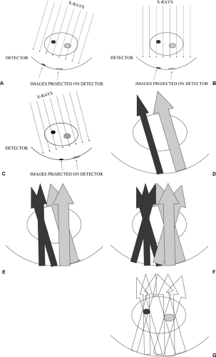 Figure 28-4 Filtered back-projection. Cross-sections of the body can be created from multiple projection images. X-ray images are obtained from multiple different projections (A–C). The beams pass through the entire object so that the projected features recorded on the detector are a combination of all of the features through which the x-rays passed. The object that was imaged and the structures contained within it can be reconstituted by projecting the amount of radiation that was collected at each point in the detector backwards in the direction that the x-rays had come (D–F), using the total attenuation distributed evenly along the back-projection, since there is no way of telling how much the beam was attenuated at each point along its path. If a sufficient number of images are obtained from a sufficient number of projections, the cross-section can be reconstituted (G). Applying various mathematical “filters” can correct for artifacts that are inherent in the technique. |
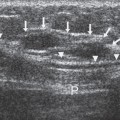
Although DBT does a remarkable job of eliminating superimposed structures, it cannot produce accurate cubic voxels that perfectly reflect the tissues through which the x-ray beam passed. The only way to do this would be to collect projection image over an arc of 180 degrees or more (like a CT scanner). By imaging from directions less than over a 180-degree arc, tissues behind a structure are seen only from an angle and not at right angles. Data are not collected that perfectly demonstrate the “back” of a structure. This means that the information about small structures, although very sharp in the x and y dimensions (essentially the pixel resolution of the detector being used) is stretched in the z (depth) dimension (Fig. 28-5). Without orthogonal data, the computer cannot be precise in determining the tissue through which the x-ray beam passed. There are numerous possible “solutions” that could give the same projection data. Our algorithm seeks the one with the “maximum” likelihood of being the true definition of the structures.
The reconstructed images are presented on a high-resolution monitor using a 1-mm slice separation so that the radiologist can rapidly “page” through the slices. The entire breast is included by the system. Although we have chosen 1-mm slice separation, this can be easily reduced by computer processing without needing additional images. Our approach to imaging calcifications involves using 0.5-mm slice separation.
Tomosynthesis is similar to CT in that it presents slices
through the breast. The advantage of DBT is that it provides cross-sectional imaging at the spatial resolution of a digital mammogram. The slices that we obtain have the in-plane (x and y) resolution of the detector that is used so that the detail in the slices is better than that of a 2D conventional mammogram because the overlapping structure noise is removed. The technology offers the potential for three-dimensional (3D) reconstructions. Using the 50-degree arc, although the x and y resolution is high, as noted above, there is uncertainty in the z (thickness) resolution. Because the 50-degree arc does not permit imaging behind structures, there is some uncertainty in the z direction. This is no problem with standard breast tomosynthesis, but it does not permit isotropic voxels. The z resolution is improved by increasing the angle of the arc.
through the breast. The advantage of DBT is that it provides cross-sectional imaging at the spatial resolution of a digital mammogram. The slices that we obtain have the in-plane (x and y) resolution of the detector that is used so that the detail in the slices is better than that of a 2D conventional mammogram because the overlapping structure noise is removed. The technology offers the potential for three-dimensional (3D) reconstructions. Using the 50-degree arc, although the x and y resolution is high, as noted above, there is uncertainty in the z (thickness) resolution. Because the 50-degree arc does not permit imaging behind structures, there is some uncertainty in the z direction. This is no problem with standard breast tomosynthesis, but it does not permit isotropic voxels. The z resolution is improved by increasing the angle of the arc.
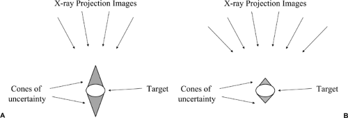 Figure 28-5 Tomosynthesis produces a variable z resolution.
Get Clinical Tree app for offline access
Stay updated, free articles. Join our Telegram channel
Full access? Get Clinical Tree


|