Introduction
Intensity-modulated proton therapy (IMPT) using pencil beam scanning (PBS) technology is advancing rapidly for delivering precise and more conformal doses to target volumes while sparing surrounding normal and critical tissues. To fully use the advantages of IMPT, immobilization and simulation is a critical step, similar to intensity-modulated radiation therapy (IMRT) and volumetric-modulated therapy (VMAT) using photons. The goal is to have small intra- and interfraction variations for the patient setup and have the setup uncertainty be well understood. It does not matter how precisely the machine can deliver the treatment; if the setup is not reproducible and appropriate for the treatment site, a precise delivery is hard to achieve. A well-designed immobilizing system can also reduce the time for daily patient setup. Devices such as headrests, Vaclock, body bags, and so on, are constructed to reduce external setup uncertainty and patient movement, whereas rectal balloons are used to reduce internal motion during treatment of prostate patients, and spacers are used to create more separation between the target volume and critical normal structures.
For radiation therapy, immobilization needs to not only immobilize the patient but also place them in a stable and reproducible position for each treatment. , Therefore, indexing of devices is very important: if there is only one device, it should be indexed to the treatment couch; if there is more than one device, each of them needs to be indexed relative to each other, and the system as a whole is indexed to the treatment couch. Accurately determining and maintaining the water-equivalent thickness (WET) along the beam path, including immobilization devices, is critically important in proton therapy. It helps to reduce the range uncertainty and the effect on proton beam penumbra. It should be pointed out that the setup uncertainty could result in a combined effect of range variations in inhomogeneous tissues of a patient, which can also alter the ranges of protons and influence dose distribution. Therefore, a good immobilization system could effectively reduce range uncertainty as well.
In general, simulations for proton therapy are similar to IMRT and VMAT because they are done using computed tomography (CT) scanners to acquire volumetric images. Magnetic resonance imaging (MRI) and other imaging modalities are also used to facilitate target volume delineation. However, a proton beam has a finite range compared with the photon. Protons deposit much of their energy at the end of the range, also known as the Bragg peak. Proton range and interaction depend on tissue or material density in the beam path; hence, CT scanners for proton therapy simulation require special considerations for calibration to establish a relationship between Hounsfield unit (HU) values and proton stopping powers (see Chapter 3 ). The interactions between photons and media are functions of the x-ray spectrum; different kV will result in different spectra. For the same kV, different scanners may have different spectra because of the difference of x-ray tube housing construction, which can act as a filter for the x-ray spectrum. Therefore, when performing a CT simulation for proton therapy, the staff should only use the CT scan protocol that is calibrated for proton therapy. In addition, one should not apply a CT-stopping power calibration curve from one scanner to CT images from a different scanner, even if the kV is the same, unless it has been verified.
Immobilization devices: General considerations
Immobilization devices for radiation oncology should have the following general properties: (1) reproducible and comfortable for the patient, (2) ease of use and setup, (3) easy in making and cleaning, (4) maintaining the rigidity and shape throughout the course of treatment for patient-specific devices, and (5) indexing to the treatment table.
Additional considerations for immobilization devices for proton therapy have been discussed by Wore et al. , At MD Anderson, we include, but are not limited to, the following considerations when designing and selecting immobilization devices for proton therapy: (1) uniform, low-density if possible, material (i.e., minimal part-to-part variability) so that it would introduce minimal range perturbation in the beam path; (2) devices with gradual slope and no sharp edge; (3) devices producing minimal imaging artifacts; and (4) avoiding the field passing part of the frame and/or table edge during treatment planning.
Various external immobilization devices, including the headrest, mask, bit block, Vacloks, wing board and T-bar, and leg-knee device, are used, depending on the disease site being treated. For moving targets, some motion mitigation strategies may have to be used, including compression boards, breathhold, and gating.
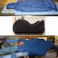
The Hitachi treatment tabletops used at MD Anderson are rectangular slabs, as shown in Fig. 4.1 , made of a foam core with a carbon fiber shell. These tabletops have the desirable properties of low density and of being homogeneous. They come in three lengths: long, medium, and short. The short one was originally intended for head and neck (HN) and brain patients. However, the rectangular shape would create large airgaps for lateral or lateral oblique fields often used for HN and brain patients. Large airgaps will enlarge the penumbra for passive scattering beam with aperture and the spot sizes with a range shifter for spot scanning beam for shallow targets. To minimize airgaps, HN couch tops specific for proton therapy were designed and manufactured. Shown in Fig. 4.2 is an example used at MD Anderson manufactured by CIVCO (Kalona, IA), in which the superior end of the couch top is contoured to have the shape of head and shoulder. Similarly, the BoS Headframe developed by Qfix (Avondale, PA) is used by some of the other institutions.


Although it has many advantages for radiation therapy, such as high mechanical strength and low specific density, the carbon fiber couch top is conducting, which limits its compatibility with MRI. On the other hand, MRI has become an indispensable imaging modality in modern radiation therapy because of its superior soft tissue contrast and other advanced imaging applications, such as diffusion-weighted imaging and diffusion tensor imaging. It is recommended to have MRI-compatible immobilization devices for proton therapy. Other materials, such as a composite of polypropylene and fiberglass, have been developed as an MRI-compatible alternative to carbon fiber. Two approaches have been suggested : (1) use the MRI-compatible couch top and immobilization devices with the same foam factor, shape, and size for imaging while the patient would be simulated and treated with the carbon fiber couch top; and (2) replace the carbon fiber all together using MRI-compatible materials for CT and MRI imaging and treatment. At MD Anderson, we currently use the first approach for all patient simulation and MRI imaging during the course of proton therapy.
Immobilization devices and modeling by the treatment planning system
The effects of the devices external to the patient receiving radiation therapy, including increased skin dose, reduced tumor dose, and altered dose distribution, were traditionally ignored as if the patient was suspended in air. Recently, this issue has been addressed by the Task Group Report 176 (TG176) of the American Association of Physicists in Medicine (AAPM). Although the dosimetric effects on photon therapy should be incorporated in the planning process and they are nevertheless small, the range errors introduced by these devices could result in the dose changes up to 100% of a proton beam to a part of the target volumes and/or normal tissues. For proton therapy, the immobilization devices, including immobilization and treatment couch top, in the beam path act as range shifters. Anything in the beam path would contribute to the WET for the beam and should be correctly accounted for by the treatment planning system (TPS). Based on these considerations, TG176 recommends that, for proton therapy, TPS should be used to calculate the WET values of the devices, comparing the TPS calculated values with measurements to ensure the devices are properly modeled.
To model the external devices in TPS, it is necessary to have the devices correctly represented in the planning CT images. A direct approach would be to include all devices used in treatment delivery during CT simulation. The treatment couch top is typically different from the CT simulator couch top. Several approaches have been used at MD Anderson to address this topic:
- 1.
For patients to be treated with beams not passing any device and couch top, such as prostate patients using lateral fields only, no special consideration is needed in this regard.
- 2.
For HN and brain patients, an identical couch top is placed on top of the CT simulator, and the patient is immobilized to the HN couch top. During CT simulation, special attention is paid to ensure the CT images include the entire couch top. A software tool was developed at MD Anderson to remove the CT scanner couch top. Fig. 4.3 shows a CT image for an HN patient with and without the CT couch top. The WET thickness of the HN couch top is 8 mm, which is within 1 mm of measured values.

Fig. 4.3
A computed tomography (CT) image for a head and neck patient with and without a CT couch top.
- 3.
For any patient to be treated with the posterior beam passing through the regular Hitachi couch top at MD Anderson, the CT couch top is replaced by a digital model of treatment couch using a different function of the same software tool mentioned in 2. Fig. 4.4 displays a CT image for a thoracic patient, with a CT scanner table and with the digital treatment couch top.

Fig. 4.4
A computed tomography (CT) image for a thoracic patient with the CT scanner couch top and with the digital treatment couch top.
After the external devices are correctly represented in CT images, it is critical to verify the WET values predicted by TPS are within the established tolerance. Typically, TPS calculates the WET value based on the CT number of each voxel and the corresponding relative linear stopping power through the CT number and stopping power calibration curve accumulated over the beam path.
The WET value of a particular device can be determined by measuring the depth dose curve with and without the device. Depth dose curves for particle beams can be measured by scanning an ionization chamber in a water tank or a multilayer ionization chamber (MLIC). , Fig. 4.5 is an example of depth dose curves with and without the Hitachi tabletop used at MD Anderson Cancer Center measured in a water tank. It was determined that the WET of the tabletop was 1.10 ± 0.05 cm. In TPS, this tabletop has been confirmed to have the same value of WET. Wroe et al. performed a WET analysis for various immobilization devices used in their clinic. It was found that multiple inserts of a commercial couch system had the WET values that were predicted by TPS within 1 mm. If the measured WET value could not be predicted by TPS, one would have to contour the device and override the HU or stopping power value such that the WET was within 1 mm of the measured value of WET of the device. In a recent study, Fellin et al. investigated the range errors introduced by modeling of WET in TPS and validation by measurements using MLIC. They found the all the devices could be predicted by TPS except one.