Mammography: Equipment and Basic Physics
In the late 1980s the American College of Radiology (ACR) developed the Mammography Accreditation Program (MAP). Initially a voluntary program, the MAP was an effort to standardize and improve the quality of mammography and mammographic equipment. In 1992 the U.S. Congress enacted the Mammography Quality Standards Act (MQSA) and appointed the Food and Drug Administration (FDA) to develop guidelines and oversee the basic quality of mammography equipment and mammography facilities in the United States. In turn the FDA certified several organizations to perform the mandated inspections of equipment and facilities. The first to be certified and the largest accrediting body is the MAP of the ACR. Several states also have been certified to accredit mammography facilities.
The ACR periodically reviews the requirements for mammography equipment and generates detailed specifications as part of the MAP (1). These have evolved over time, and the reader is referred to the ACR and FDA for up-to-date guidance and specific information. Because specifications will change as technologic advances are made, this chapter discusses general principles of x-ray imaging, many of which cannot change. An additional valuable reference is the syllabus for the 1993 and 1994 Categorical Course in Physics for the Radiological Society of North America, Technical Aspects of Breast Imaging (2). More recently Hendrick and Berns provided a detailed analysis of image optimization for screen film mammography for those seeking greater detail (3). The latest information on ACR requirements can be found at http://www.acr.org/departments/stand_accred/accreditation/mammo/mammo.html.
The latest mammography equipment specifications can be found at http://www.acr.org/departments/stand_accred/accreditation/qcm/doc/mqsa_eqpt_rqmts.doc.
Although digital mammography systems have become commercially available, they have not yet replaced conventional film/screen systems because of their increased cost, the need for a digital archiving system, and the fact that, other than logistical improvement, digital mammography has not been shown to be better at detecting breast cancer than conventional mammograms (see “Digital Mammography”). Digital mammography systems have been shown to be equivalent in lesion detection and analysis to film/screen systems, but it is still not clear that they are superior. Once digital breast tomosynthesis becomes commercially available, there will be a rapid shift to this new digital technology (see “Digital Breast Tomosynthesis”) because these three-dimensional digital mammography devices will lead to an increase in breast cancer detection (sensitivity) while reducing the false-positive callback rate (specificity). Nevertheless, the generation of x-rays, the physics of x-ray interaction with breast tissues, and the conversion of the x-rays exiting the breast into a mammographic image will still follow the basic physical principles described below.
Basic Principles of X-Ray Mammography
The ultimate goal of x-ray mammography is to produce detailed images of the internal structures of the breast to permit the earlier detection of breast cancer. Because fine detail is needed, the process requires images with high spatial resolution. Because the inherent x-ray attenuation differences (tissue contrast) between normal and diseased breast tissues is so small, high-quality mammography requires the ability to enhance those differences and provide high-contrast resolution. Producing such images involves a complex interaction of many interrelated factors (Fig. 8-1).
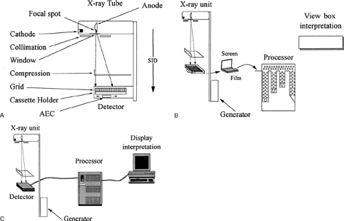 Figure 8-1 The mammography imaging chain. Conventional mammography requires that all components of the imaging sequence be performed properly. This includes the x-ray device and its components, including the x-ray tube and its cathode, anode, focal spot, window, filtration, collimation, source-to-image distance (SID), and the compression system automatic exposure control (AEC) A; the detector and its components, including the cassette, film, and screen; or the solid-state detector, the film processor, and its components; and the interpretation system (view box or computer display). All of these components are interrelated. Alterations at any point in the sequence can influence the operation of the other elements. Even though the detector and display are different between conventional mammography B and digital mammography C, the interactions of the constituents of the system must be carefully matched and properly adjusted. |
Every component of the imaging sequence influences the resulting image and can affect the ability to detect early breast cancer. Ultimately, the image is formed by the detector, and it is the requirements of the detector that dictate the imaging parameters. Film/screen combinations, for example, require sufficient exposure to be certain that when the image is processed, the resulting picture will be optimized for viewing on a view box. This has inherent disadvantages because the characteristics of the film as a viewing medium dictate the various components of the imaging sequence and the exposure values. The development of digital mammography permits greater optimization of the exposure parameters because image generation and viewing is independent of exposure.
Film has a complex, sigmoid-shaped response to x-ray exposure and the light the photons stimulate in the intensifying screens. Because low levels of exposure produce little change on the film, there is little contrast between tissues of high x-ray attenuation (the white areas of the film) because of the characteristics of the film at the “toe” of the curve. To enhance the attenuation differences between normal and malignant lesions and to provide contrast in the high-attenuation areas of the breast (the fibroglandular tissues), greater exposure is needed to move to the portion of the Hunter and Driffield (H&D) curve (Fig. 8-2) to where small changes in the amount of radiation reaching the detector lead to large changes in film blackening (higher contrast). This can be seen by comparing optical density on the film to contrast on a gamma plot. Optimal imaging is at the peak of the gamma plot. Contrast is improved when the peak is high and over a large range of optical density. This corresponds to the exposures that record the x-ray attenuation on the steeply sloped linear portion of the H&D curve where small differences in tissue contrast are amplified. At high exposures, the film density changes begin to level out (the “heel” of the curve) and contrast is no longer enhanced. The toe and heel of the film’s response to light are among where contrast is the poorest, and part of the limitations of film.
Direct digital acquisition of an x-ray image is not restricted in this fashion because the image display is not affected by the factors involved in image acquisition. Digital detectors have essentially a straight-line response to x-ray photons, regardless of the level of exposure. This permits the maximum contrast separation and greater room to explore potentially even better ways to image the breast with x-rays.
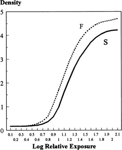 Figure 8-2 These Hunter and Driffield (H&D) curves relate the amount of exposure to the density (blackening) of the film for a system (S) with a longer gray scale and less contrast than (F), which represents a faster film (less exposure is needed for the amount of blackening) with greater contrast (the curve rises more quickly with increasing amounts of exposure). |
Film and Screen Imaging
Haus (4) has summarized the various components of the film and screen mammographic image. He divided radiographic sharpness into contrast and blur (“unsharpness”).
Contrast
The inherent “subject contrast” is the difference in x-ray attenuation of the various breast tissues through which the x-rays pass relative to the adjacent tissues, and this is determined by their thickness, density, and atomic composition. The contrast that can be demonstrated by an image is related to the transmission of x-rays through the tissues (penetration). This is influenced by the beam quality (the energy and number of photons), which is a function of the anode/target material, the kilovoltage of the beam, and the material used to filter the x-ray beam. The ultimate contrast is also influenced by the amount of scatter reaching the film, which is influenced by the collimation of the beam, thinning of the breast by compression, any air gap between the breast and the detector, and by scatter-reducing grids or slit collimation. The inherent tissue contrast is amplified by the contrast generated on the film or digital detector system. The film image is influenced by the type of film used, its processing (i.e., chemistry, temperature, time, and agitations) and factors that compromise the photographic image, including fog from improper storage, inappropriate safelights, and light leaks.
Blur
Haus breaks blur into several components, beginning with direct blurring due to actual breast movement during the exposure. Blurring due to motion can be reduced by compression to immobilize the breast and also by shortening the exposure time. Geometric blur (formally called geometric unsharpness) is the blurring of detail due to various components of the imaging chain, many of which interact with one another. Altering one component may negatively influence the other. One source of blur is related to the size of the focal spot. The blur due to a large focal spot can be balanced by using a longer distance from the tube to the breast and the detector (the source-to-image distance). The amount of blur is also related to the distance of the object to the detector. There is also blur related to the thickness of the phosphor of the screen that converts the x-ray photons to light. Blur is also influenced by the particle size of the phosphor, and the contact between the film and the screen. The amount of blur influences the ability to see fine detail. One goal for improving x-ray imaging of the breast is to minimize blur.
Noise
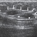
Noise is another source of image degradation. Noise can come from various sources. It is essentially a random signal that can hide the signal that provides the useful information. Noise in an x-ray image begins with the x-rays themselves. Nonuniformity, or mottle, in the image is a function of the quality of the x-ray beam (kVp and mAs), which influences that quantity of x-ray photons reaching the detector (quantum mottle). An x-ray image can be thought of as being painted by a series of dots. Each dot is produced by an x-ray photon. Too few photons make the image “noisy,” with inhomogeneities and reduced definition of structures (Fig. 8-3). The more dots that make up the picture, and the closer together they are, the clearer the picture. When there are more x-ray photons reaching the detector, the image is much clearer than when fewer photons reach the detector. The grain of the film is another source of noise. These are finite in size, and if the film image is enlarged, the inhomogeneity of the film grain becomes apparent. When the size of calcifications, for example, is very small, the spot on the film caused by the calcification cannot be differentiated from the grain of the film emulsion.
Mottle is also influenced by the speed and contrast of the film, the absorption characteristics of the screen, and its efficiency in converting x-ray photons to light photons. Although film responds to x-rays directly, this is very inefficient, and the image is made by converting x-rays to visible light, which is much more efficient at exposing film. The conversion of x-rays to light photons by a fluorescing screen adds additional noise to the image and adds blur because the light is diffused by the screen, reducing the sharpness of the ultimate image. Finally, the normal breast tissue structures that superimpose on one another and can hide cancers produce what is termed “structure” noise. All of
these factors conspire to reduce the sharpness and contrast and make it more difficult to interpret mammograms.
these factors conspire to reduce the sharpness and contrast and make it more difficult to interpret mammograms.
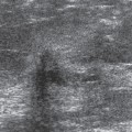
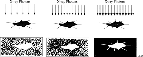 Figure 8-3 Quantum mottle is a function of the number of photons that reach the detector. If few photons reach the detector, the shadow of the object will be indistinct A. Increasing the number of photons improves the clarity of the object being imaged B. The greater the concentration of photons, the clearer the image C. |
Artifacts
There are numerous sources of artifacts that also compromise the image. These may be on the patient, such as antiperspirant, ointments, and powders. The film may be crimped or scratched during handling. Fingerprints may cause negative as well as positive artifacts. Static electricity can also cause artifacts. The film processor can produce streaks, spots, and scratches, among other artifacts.
Film/Screen Detectors
The primary problem in using film as the detector as well as the display medium is that virtually all imaging parameters are interrelated, and a modification of any one component may dramatically influence other parameters affecting the resultant image. Each improvement in one component usually forces a compromise in another to compensate. Although an improvement, even digital detectors result in compromises.
Most film/screen mammographic systems represent a balance among the various elements of the imaging sequence. This process begins with the generator, the generation of electrons, the composition and shape of the focal spot, and the type of beam filtration. Together these generate an x-ray spectrum that should be optimized for the tissues being imaged and the requirements of the recording system. The generator is one of the major determinants of the speed with which the exposure can be made and the quality (energy) of the x-ray beam. The type of material chosen for the focal spot influences the focal spot size and x-ray output. Because the inherent contrast between breast tissues and lesion in the breast is fairly low, efforts have gone into trying to amplify those subtle contrast differences. The beam quality determines x-ray and tissue interactions that produce contrast separation. Tissue differences are enhanced using “softer” x-rays. This is very important for film/screen imaging. Because of computer manipulation, digital imaging does not require soft x-rays because the contrast can be recaptured by computer processing.
The quality of the beam also influences the amount of image-degrading scatter from x-ray interactions at the atomic level in the tissues. When the direction of some of the primary beam photons is altered (scattered), contrast is compromised. This results in the need for a scatter-reduction grid or slot-type collimator, as used in the Fisher digital mammography system. With the exception of the Fisher system, which protects the breast from unused primary x-rays, the addition of a scatter-reduction grid necessitates increased dose. The grid blocks the scatter photons but also blocks the primary beam, and essentially a second exposure must be made to image the area under the grid after it is moved to its other position (assuming half the image is covered when the grid is stationary).
As with all x-ray systems, as the focal spot size is reduced, the potential spatial resolution increases. Unless heat is more efficiently dissipated, however, photon output must diminish as the size of the focal spot is reduced so that the heat generated by concentrating the electron flux on a smaller area of the anode does not destroy the tube. Because photon flux drops as the square of the distance that the
x-ray source is moved from the detector, a decline in output influences the distance that the focal spot can be from the object to be imaged and from the detector, which affects sharpness, blur, and spatial resolution. Output, based on the generator, x-ray tube, and tube distance, and the detection efficiency of the recording system influence the time required to produce an optimal exposure. Longer exposures lead to disproportionately higher doses in film/screen systems as a result of reciprocity law failure (see “Reciprocity Law Failure”). The engineering characteristics of the system influence the object (breast structures and lesions)-to-detector distance, affecting magnification and spatial resolution. The body habitus of the patient and the interface between the patient and the machine may be limited to accommodate technical requirements.
x-ray source is moved from the detector, a decline in output influences the distance that the focal spot can be from the object to be imaged and from the detector, which affects sharpness, blur, and spatial resolution. Output, based on the generator, x-ray tube, and tube distance, and the detection efficiency of the recording system influence the time required to produce an optimal exposure. Longer exposures lead to disproportionately higher doses in film/screen systems as a result of reciprocity law failure (see “Reciprocity Law Failure”). The engineering characteristics of the system influence the object (breast structures and lesions)-to-detector distance, affecting magnification and spatial resolution. The body habitus of the patient and the interface between the patient and the machine may be limited to accommodate technical requirements.
Ultimately, resolution is limited by the ability of the detector to record and display the detail that the other elements of the system present to it. The optimization of the components of the imaging chain is limited by the available technology, and compromises are often necessary. An ideal mammography system would have an infinitely small focal spot capable of the instantaneous production of an unlimited number of appropriately low-energy photons, with a detector that had unlimited dynamic range and was able to detect every photon that directly transited the breast. There is no ideal mammographic system.
X-Ray Production
Kilovolt Peak
X-ray tubes are designed to take electrical energy in the form of electrons that are boiled off a filament and accelerated toward a piece of metal so that the collision with the metal converts the electron energy into x-ray photons. Virtually all x-ray tubes used for medical imaging (with the exception of experimental devices) generate x-rays by passing an electrical current through a metal wire or ribbon (the cathode filament). Because of the resistance of the filament, some of the energy of the current passing through the filament is converted to heat. The high temperatures cause electrons to “boil” off the metal cathode. Electrical forces are used to accelerate these electrons away from the cathode and toward the anode, which is composed of a metal specifically selected for the types of x-rays generated by the electron impacts. When the electrons strike the anode, part of their energy is converted into x-ray photons and part is converted to heat. Many of the limitations of standard x-ray tubes lie in the heat limitations of the cathode filament and the capacity of the anode to handle the heat that is generated by the beam of electrons focused on it.
The type and energy of the x-ray photons generated are determined by the energy of the electrons and the composition of the anode. Many photons are created by bremsstrahlung, which is German for “breaking radiation.” As electrons penetrate the anode, those that pass close to the nucleus of the anode atoms are slowed by the attraction to the nucleus. In slowing, they give up varying amounts of energy, which is converted to x-ray photons of correspondingly varying energies.
The energies of the bremsstrahlung photons depend on the energy of the electrons that produce them and the proximity of the electrons to the nucleus as they pass through the atom. These photons cannot have any higher energy than the electrons that were responsible for their production, but they produce a spectrum of low-energy x-ray photons. The highest energy in a beam of photons is determined by the energy imparted to the electrons as they are accelerated from the cathode to impact on the anode. This energy is described as the kilovolt peak (kVp); it represents the peak energy of the photons being generated.
X-Ray Spectra
The spectrum of energies included in the entire beam is determined by other factors, including kVp. Most of the interactions produce heat and no x-rays. The majority of photons emitted due to bremsstrahlung are usually generated with energies that are considerably lower than the kVp. These photons are most abundant at the low energies but range up to the kVp.
Characteristic X-Rays
Some x-ray photons are generated with specific energy characteristics. Interactions between the accelerated electrons and the atoms of the anode produce “characteristic” x-rays. This term is given because they have energies that are characteristic of the material that generated them. For characteristic x-rays to be generated, accelerated electrons must have sufficient energy to knock out an electron in one of the outer shells of the atom. The loss of an electron produces an unstable situation. The displaced electron is quickly replaced by another of the atom’s electrons from a higher energy level. In dropping from a higher energy level to a lower energy position, the electrons release energy in the form of x-ray photons. Because these photons are generated by electrons moving between discrete energy levels that are dictated by the atomic number of the atom, their energies are discrete and “characteristic” of the atom that generated the photons. The generation of these photons, with their specific energies, is one reason the composition of the anode is so important.
The quality of the characteristic radiation depends on which electron shells are involved. The most common anodes used for film/screen mammography are molybdenum, rhodium, and tungsten. The characteristic x-ray photons emitted by a molybdenum target are predominantly at 17.4 keV of energy, with a smaller contribution from 19.7 keV. Those produced by rhodium are predominantly at 20.2 keV, with a small contribution at 22.8 keV; tungsten
has a characteristic emission at 59 keV (along with other very low-energy peaks). The characteristic radiations of molybdenum and rhodium are particularly valuable for film/screen imaging because they provide an abundant source of low-energy photons that help enhance the inherently low contrast between tissue of the breast and breast cancer. It is likely that digital detectors will be able to take advantage of more heat-tolerant focal spots such as tungsten because computer processing can recover much of the contrast that is lost by using higher-energy photons. More heat-tolerant tubes that produce more energetic (and penetrating) photons will allow faster exposures and improved imaging using digital detectors.
has a characteristic emission at 59 keV (along with other very low-energy peaks). The characteristic radiations of molybdenum and rhodium are particularly valuable for film/screen imaging because they provide an abundant source of low-energy photons that help enhance the inherently low contrast between tissue of the breast and breast cancer. It is likely that digital detectors will be able to take advantage of more heat-tolerant focal spots such as tungsten because computer processing can recover much of the contrast that is lost by using higher-energy photons. More heat-tolerant tubes that produce more energetic (and penetrating) photons will allow faster exposures and improved imaging using digital detectors.
X-Ray Generators
The electrical power supply of the mammographic system is among several factors that determine the x-ray output and beam quality. The generator determines the kVp and the timing involved in x-ray production. Constant potential generators produce an essentially continuous output at a single voltage level. The least efficient generators were single phase, in which the kVp was reached over a period of time. Three-phase generators were an improvement, but constant potential is needed to provide more uniform photon energies. Uniform photon energy is important because it provides a “purer” x-ray output. Constant potential virtually eliminates the fluctuations (ripple) in x-ray generation that were inherent with three-phase as well as the earlier single-phase equipment. By producing an almost immediate and constant voltage and beam energy, exposure times are diminished and beam energy profiles are more uniform.
Focal Spot Size and Geometric Considerations
X-ray mammography demands high resolution to image the fine structures of masses and the morphologic characteristics of small calcifications that often indicate early-stage breast malignancy. Particles as small as 150 μm can be imaged under optimal conditions, and greater resolution is being sought. The visibility of lesions is related not only to the spatial resolution of the imaging system but also to the contrast of the lesions compared to the surrounding tissue and the sharpness of the imaged structures (the opposite of blur). Resolution is determined by the size of the focal spot, by its distance from the structure within the breast to be imaged, by the distance of that structure to the detector, and ultimately by the ability of the detector to produce the image and the display to display the image.
The focal spot is a key component of the mammographic system. The configuration of the focal spot varies with the x-ray tube. Various methods of generating x-rays from the anode are used, which result in focal spots that vary from round, to rectangular, to bipolar. The focal spot is actually an area on the anode where the electrons, accelerated from the cathode, strike the anode. In addition to the generation of x-ray photons, these impacts result in the production of heat. If the energies and time to generate photons were not limited, the heat would melt and destroy the anode. The capacity of the tube to dissipate this heat (heat capacity) determines its output characteristics. The design of focal spots is a compromise between the need to have as small a spot size as possible, but one that can produce large numbers of photons over short periods of time, balanced against the need to prevent the anode from melting. Tube designs rely heavily on geometry to accomplish this.
To keep heat loading down, milliamperes (photons) up, and focal spot size small, the area on the anode that constitutes the focal spot is actually larger than the “apparent” focal spot. In addition, in most modern tubes the area struck by the electrons is constantly changed by rotating the anode to reduce heat buildup. The electrons are focused on a large area that is tilted relative to the incident beam of electrons and the breast (Fig. 8-4). In this fashion, the area over which the anode generates photons (and heat) is much larger than the apparent focal spot. This can be understood by looking from the breast back up at the
anode. Depending on its location on the breast, the focal spot will appear to be quite small (toward the nipple side), and it will appear to enlarge as the perspective moves toward the chest wall (Fig. 8-5). This means that the sharpness of the image varies over different parts of the breast related to the apparent size of the focal spot, and the geometric unsharpness or blur will depend on which part of the image is being considered. Unfortunately, as the apparent focal spot gets smaller away from the chest wall, there is also a drop of photon flux due to the heel effect (see below).
anode. Depending on its location on the breast, the focal spot will appear to be quite small (toward the nipple side), and it will appear to enlarge as the perspective moves toward the chest wall (Fig. 8-5). This means that the sharpness of the image varies over different parts of the breast related to the apparent size of the focal spot, and the geometric unsharpness or blur will depend on which part of the image is being considered. Unfortunately, as the apparent focal spot gets smaller away from the chest wall, there is also a drop of photon flux due to the heel effect (see below).
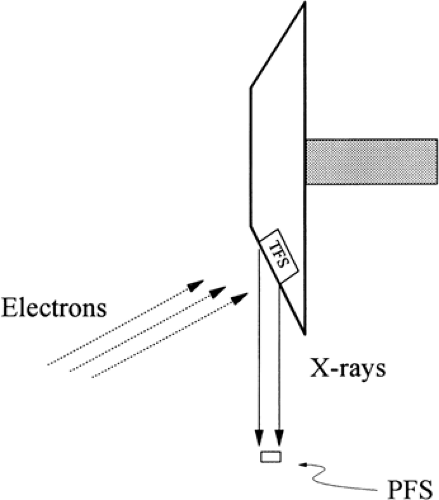 Figure 8-4 The anode surface is at an angle relative to the stream of electrons generated from the cathode and to the breast. This presents a larger area from which to generate photons (TFS), but the “projected” focal spot (PFS) looks smaller on the breast, increasing spatial resolution. |
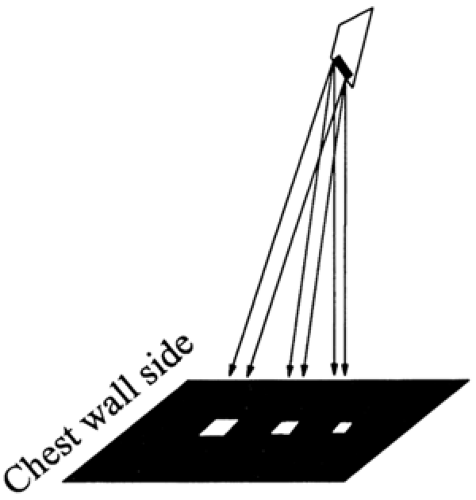 Figure 8-5 Mammography tubes are oriented by angling either the anode or the tube so that the smallest projection of the focal spot is at the nipple side; it becomes progressively larger toward the chest wall. This schematic demonstrates how the “apparent” focal spot becomes progressively smaller away from the chest wall. Because the heel effect begins to limit the photon flux as the projected spot size diminishes, the orientation of the focal spot is matched to the thinner front of the breast, which can be properly exposed with the diminished flux. The thicker chest wall side of the breast receives the most output. |
“Nominal” Focal Spot Size
Geometric unsharpness would be eliminated if the focal spot were infinitely small. The closer the focal spot is to the idealized “point source,” the better the possible spatial resolution of the system. Manufacturers are permitted to claim focal spot sizes that may, in reality, be considerably larger than the “nominal” figure that they quote. Dimensions of the focal spot may be 50% larger than the stated “nominal” size. For example, a nominal 0.4-mm focal spot may be as large as 0.6 mm. The actual size of the focal spot should be measured before a system is accepted.
Heel Effect
As with most factors involved in mammography, because the small focal spot is achieved by angling the anode, as the apparent focal spot size decreases, the output of the focal spot also decreases because of the heel effect. This occurs in the portion of the x-ray field in which the focal spot-to-detector angle is the most obtuse. Because the angle of the exiting x-rays generated from this part of the focal spot is so steep, the apparent focal spot at this end is very small, but unfortunately many of the photons generated at this end are reabsorbed by the anode itself. This means that the output, seen at the breast, is diminished. Tubes are oriented so that this heel falls on the thinnest anterior portion of the breast, where lower flux can be tolerated.
Blur Due to Geometric Unsharpness
One major form of blur in the image is due to geometric unsharpness. Although they approximate a point source, even the smallest focal spots produce geometric blurring if they are too close to the structure to be resolved, the structure is too small to be resolved, or the structure is too far away from the detector. As noted above, the blur from geometric unsharpness is the result of x-rays that are emanating from all over the focal spot. If, for example, the focal spot is rectangular, then x-rays are generated from both ends as well as the middle. The shadows cast from the x-rays generated from the ends of the focal spot are slightly different from one another, and their inexact overlap (as well as the shadows from those generated in between) causes the blur. This produces a main shadow (the umbra) of structures in the breast that is surrounded by a less sharp secondary shadow (the penumbra) (Fig. 8-6). The penumbra blurs detail. As the name implies, geometric unsharpness is loss of sharpness due to the geometry of the system as it relates to the size of the focal spot, the object whose shadow is being cast, and the distance of the object from the detector (Fig. 8-7). If the object is in direct contact with the detector, then there would be no blur from the geometry of the relationship;
the shadow of the image would be crisp. If the object is at some distance from the film, its edges will be blurred in relation to the distance it lies away from the detector, the size of the focal spot that is generating, the x-rays, and the distance of the focal spot from the object being imaged and from the detector. This is because the focal spot, although very small, has a finite size, and x-rays come from all along its surface following divergent paths. Blur from geometric unsharpness is reduced by using equipment that is designed for mammography and uses as small a focal spot as possible.
the shadow of the image would be crisp. If the object is at some distance from the film, its edges will be blurred in relation to the distance it lies away from the detector, the size of the focal spot that is generating, the x-rays, and the distance of the focal spot from the object being imaged and from the detector. This is because the focal spot, although very small, has a finite size, and x-rays come from all along its surface following divergent paths. Blur from geometric unsharpness is reduced by using equipment that is designed for mammography and uses as small a focal spot as possible.
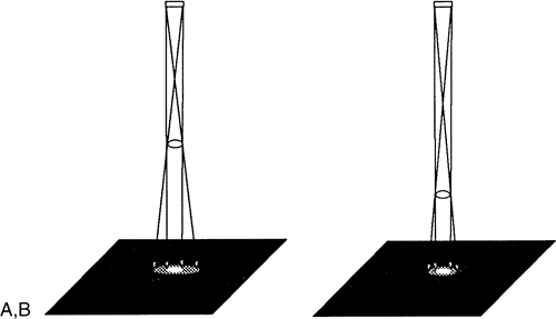 Figure 8-6 Because the focal spot has a finite size and x-rays come from both ends as well as the middle, a secondary shadow (the penumbra) is produced A that can overlap and blur the primary shadow. This can be reduced by pressing the object (breast structures) closer to the detector, which reduces the size of the penumbra and improves the sharpness of the shadow B. |
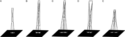 Figure 8-7 Because the focal spot has dimension (it is not infinitely small), photons come from both ends as well as the middle. This causes an object to cast primary (umbra) and secondary (penumbra) shadows A. The ability to resolve objects and distinguish one as separate from another, such as these two round structures B, is related to many factors. The spatial resolution of a system can be reduced, causing geometric unsharpness (blur). If the shadows (both primary and secondary) do not overlap, the two objects will be seen as separate. Blur is increased when the secondary shadows of two adjacent structures are enlarged so that they overlap. This makes it less likely that the observer will be able to tell that the structures are indeed separate. This occurs when the objects are moved farther away from the detector C, the focal spot is made larger D, or the focal spot is brought closer to the objects E. |
Blur due to geometric unsharpness is easily understood by comparing the generation of a mammogram to projecting the shadow of your hand on a white wall using a bright light. The less focused the light source (comparable to a large focal spot), the closer the object is to the light source, or the farther the object is from the white wall, the greater the blurring of the shadow of your hand. This phenomenon is easily demonstrated using the light from a slide projector. If an object is held up between the light and the screen, its shadow becomes increasingly better defined as it is moved closer to the screen. As it is moved away from the screen, its margins become blurred. Similarly, the smaller the light source or the farther away the light source is from the object and the screen, the sharper the shadow of the object.
To reduce geometric unsharpness using x-rays, the focal spot must be moved as far away from the object and detector as possible, the focal spot must be as small as possible, and the object to be imaged must be pressed as close to the detector as possible. This latter requirement is one reason the breast needs to be physically compressed against the detector surface.
Haus et al (5) calculated that a 1-mm focal spot 28 cm from a structure can resolve 6 line-pair (lp)/mm for structures 5 cm above the recording surface. Because the size of the penumbra relative to the main shadow cast on the film is reduced as the focal spot is moved away, this same focal spot can resolve 15 lp/mm if it is positioned 75 cm from the object to be imaged. This might be desirable, but because the photon flux decreases with the square of the distance (the inverse square law) that the focal spot is moved away, the demands on the x-ray tube increase rapidly.
The resolution of a system is governed by the interaction of its components, but by holding these constant, Haus et al used actual mammographic systems to determine the changes in resolution that occur with variation in focal spot size, in focal spot-to-object distance, and in distance of the object from the detector. The experimental findings correlated well with the theoretic prediction that the resolution of a system is inversely related to the size of the focal spot and the distance of the structure from the detector, and directly related to the distance from the focal spot to the lesion. This relationship is summarized in the empirically derived equation: ALP/mm = 1.1 × [FOD/(FS × ODD)], where ALP/mm is the approximate resolution in lp/mm, 1.1 is a constant, FOD is the distance (in cm) from the focal spot to the object to be resolved, FS is the size of the focal spot (in mm), and ODD is the distance (in cm) from the object to the detector.
Thus, for a specific focal spot size and a lesion a given distance from the detector, resolution increases directly with the distance of the focal spot from the object to be resolved. Doubling the distance doubles the resolution. Similarly, making the focal spot half the size will also double
the resolution, as long as none of the other variables is changed.
the resolution, as long as none of the other variables is changed.
Resolution can also be increased by taking advantage of the divergence of the x-ray beam and moving the focal spot closer to the object being imaged and moving the object away from the detector. Because of beam divergence, the shadows enlarge and magnification will result (see “Magnification Mammography”). This will be useful only if sharpness is maintained, which requires that the focal spot size be reduced to avoid the geometric blurring that increases as the distances are changed. Although the improved visibility of structures with actual radiographic magnification is primarily due to a reduction of noise (6), if the focal spot is sufficiently small, magnification will result in an absolute increase in spatial resolution (see below).
Variation in Actual Spatial Resolution
The relationships discussed above assume that the detector itself can display the resolution achievable by the system, which may not be the case. Modern mammographic film/screen combinations have an inherent resolution capability of approximately 15 to 20 lp/mm. Because of the other contributions to unsharpness, however, the actual resolving power of film/screen mammography systems, operating as clinical instruments, is considerably less. Systems are required to be able to resolve approximately 13 lp/mm with the line pair bar pattern placed 1 to 2 cm from the chest wall side of the detector and 4.5 cm above the film plane with the lines of the phantom oriented parallel to the anode–cathode axis. When the pattern is turned so that its lines are perpendicular to this axis, the resolution may be even lower, because most focal spots are usually narrower than they are tall.
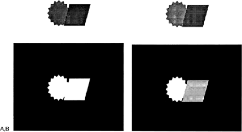 Figure 8-8 Spatial resolution has little benefit if there is no contrast. Even though there is high spatial resolution, these two objects A appear as one on the film because there is insufficient ability to separate their slight differences in contrast. With improved contrast resolution, they can be distinguished B. |
Stay updated, free articles. Join our Telegram channel

Full access? Get Clinical Tree


