Practical Aspects of External Beam Therapy
Key Points
Patient positioning, immobilization, and placement of an isocenter (or a reference point) are critical components for planning external beam radiotherapy.
Supine position is most desirable for the vast majority of patients.
Use of radiopaque markers can aid delineation of target volume.
Positional or shielding stents are useful for decreasing radiation dose to normal tissues in certain cases.
CT-based plan with heterogeneity correction is the current standard method.
Intensity-modulated radiation therapy (IMRT) is increasingly used for treating head and neck cancer for improving target volume coverage around the skull base (e.g., nasopharyngeal and sinonasal carcinomas) and for reducing radiation exposure of normal tissues such as salivary glands, cranial nerves, spinal cord, brain stem, etc.
Unilateral radiation is preferred for selected patients with lateralized neoplasms such as cancer of the buccal mocosa, retromolar trigone, parotid, etc.
Bolus, missing tissue compensator, and other devices can improve dose distribution but their use is diminishing with the introduction of IMRT that provides better conformation of radiation to the target volumes.
PATIENT POSITIONING
The supine position is most frequently used to deliver radiation with the conventional technique or intensity-modulated radiation therapy (IMRT). An isocentric technique is applied for matching opposed-lateral fields or IMRT upper neck portals to an anterior or anterior-posterior (AP-PA) lower neck portal(s).
The “open neck” position, in which the head is rotated on the trunk, resulting in flattening of the contours of the neck, is used for irradiating lateralized tumors and the ipsilateral neck. This position is suitable for irradiations with adjoining appositional electron fields or with a wedge-pair photon portal matched to an appositional electron field for lower neck.
The true lateral position is used in very select cases, for example, postoperative situations in which patients are unable to control secretions in the supine position but nonetheless need to be treated with opposed-lateral fields.
The seated position is used very rarely, primarily for those who have difficulty managing their secretions or those who have difficulty breathing in the supine position. Treatment is accomplished using a specially designed chair mounted to the treatment couch. This chair enables the same immobilization and allows the same treatment accessories to be used as in the supine position. The chair is used only if other options are not feasible because complex treatment planning and dosimetry are difficult and because computed tomography (CT) scanners cannot accommodate patients in this position.
PATIENT IMMOBILIZATION
Virtually all patients nowadays are immobilized with thermoplastic masks that are individually made in the desired treatment position. A variety of commercial
neck pads and head holders are available for the purpose of immobilization in different positions. When making a mask, care should be taken to stretch the thermoplastic sufficiently thin to avoid unwanted bolus effect. For treatments limited to the neck region, the mask can be constructed so as to avoid the portals altogether. Figures 3.1 and 3.2 outline briefly the general procedure of constructing immobilization devices.
neck pads and head holders are available for the purpose of immobilization in different positions. When making a mask, care should be taken to stretch the thermoplastic sufficiently thin to avoid unwanted bolus effect. For treatments limited to the neck region, the mask can be constructed so as to avoid the portals altogether. Figures 3.1 and 3.2 outline briefly the general procedure of constructing immobilization devices.
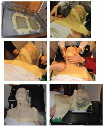 Figure 3.1 Procedure for making a thermoplastic mask in a supine position. A: Thermoplastic sheet is submerged in a warm water bath (72°C) until it becomes flexible. B,C: The thermoplastic sheet is placed over the head and shoulders of the patient, aligned in the desired position, and the frames are then fixed to a head holder by clamps. Care is taken to stretch the thermoplastic sheet sufficiently thin to avoid unwanted bolus effect. D: Gentle pressure is applied to make the thermoplastic sheet conform to the contours of the head and shoulder while cooling off and becoming more rigid. E,F: Isocenter or reference point is marked and thin-slice CT images are obtained for delineation of target volumes or portals and dosimetric planning. |
Introduction of IMRT to reduce radiation morbidity or to escalate radiation dose to improve tumor control demands more precise and reproducible immobilization technology. Several methods have been introduced, which can be grouped into invasive and noninvasive techniques. Invasive techniques use head immobilization frames similar to those used for stereotactic radiosurgery. The frame is affixed to the patient’s skull by several screws, usually placed by a neurosurgeon.
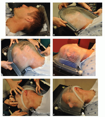 Figure 3.2 Procedure for making a thermoplastic mask for treatment in an open neck position. A: The patient is positioned with the head rotated on the trunk to flatten the contours of the neck. B-D: The thermoplastic sheet is stretched over the head of the patient and the frame is then fixed to a head holder. E,F: Gentle pressure is applied to make the thermoplastic sheet conform to the contour of the patient and the sheet is rolled up cranially to expose the area of irradiation to minimize perturbation of electron beams. Simulation can take place while the mask is cooling down and becoming more rigid. |
Numerous noninvasive immobilization techniques have been described. They are based on thermoplastic mask immobilization or customized polyurethane cradles. Thermoplastic masks can be reinforced with additional straps to increase rigidity. Some systems add individualized cradles for support of the occiput. We currently use a longer headboard for attachment of a mask that extends from the vertex of the scalp to the upper chest, giving additional support to the upper neck and shoulder (Fig. 3.1).
RADIOPAQUE MARKERS AND STENTS
Although CT scan-based simulation and dosimetry are widely used, radiopaque markers can still be useful for delineating the scars and, in select cases, the primary lesion. It is important to realize that it is often difficult to visualize superficial tumors in the diagnostic or planning CT scan. This simple procedure helps in designing treatment portals to minimize the risk of a geographic miss and to avoid unnecessary inclusion of normal tissues. Several types of custom-made stents are useful in reducing the volume of normal tissues irradiated.
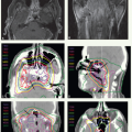
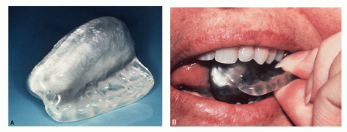 Figure 3.3. A 37-year-old woman presented with a 1.5-cm mass at the left angle of the mandible. The head and neck examination was otherwise unremarkable, and the facial nerve function was intact. Material for cytologic study was obtained by fine needle aspiration and was interpreted as pleomorphic adenoma. At surgery, the tumor was found to be mainly located in the deep lobe of the parotid gland. It was well encapsulated and was dissected out along with the surrounding normal parotid tissue. The facial nerve was preserved. Pathologic examination revealed an acinic cell carcinoma measuring 2.4 cm in maximum diameter. All gross tumor was resected, but tumor cells extended to the surgical margin. Therefore, postoperative radiotherapy was recommended. The left parotid bed was treated with an ipsilateral appositional field using a combination of 20-MeV electrons and 18-MV photons, weighted 4:1, respectively. A dose of 56 Gy was delivered in 2-Gy fractions, specified at the 90% isodose line. To reduce the dose to the underlying brain during the electron treatments, 2 cm of beveled bolus was placed over the superior part of the field. After a dose of 44 Gy, the field was reduced off the spinal cord, and treatment to the postauricular and posterior cervical area was completed with 12-MeV electrons. A custom-made intraoral stent containing cerrobend (Lipowitz’s metal, Cerro Metal Product, Bellefonte, PA, or Belmont Metal Inc, Brooklyn, NY) with a flange containing occlusal registration (A) was used to shield the tongue and contralateral oral mucosa from the electron beam treatments. The stent was held in place by the teeth fitting in the flange on the lateral side (B), which positioned the main stent between the alveolar processes and the tongue and, thereby, shielding as shown on the portal image |
Wires and seeds placed on the skin, on the thermoplastic mask, or inserted into the tissue are helpful in marking the boundaries of the primary tumor, nodal biopsy sites, or surgical scar.
Stents can be custom-made, such as those used to depress or shield the tongue or to protrude the lip. In general, these devices can be categorized into two basic types: shielding stents and positional stents. A shielding device serves to reduce the radiation dose administered to normal tissues by incorporating shielding material, whereas a positional device serves to displace normal tissues out of the treatment fields (Figs. 3.3, 3.4, 3.5, 3.6 and 3.7).
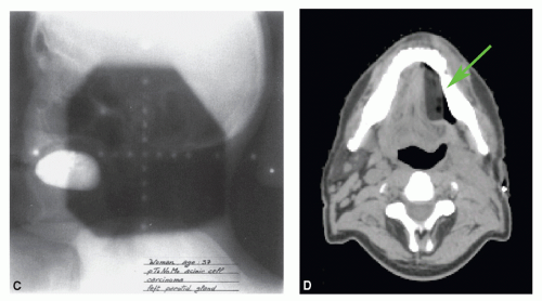 Figure 3.3 (Continued) (C) and displacing the tongue toward the contralateral side as shown on planning CT scan (green arrow) (D). Because 80% of the dose was delivered by electrons, there was still a significant protection of the tongue and contralateral oral mucosa so that mucositis could be prevented. |
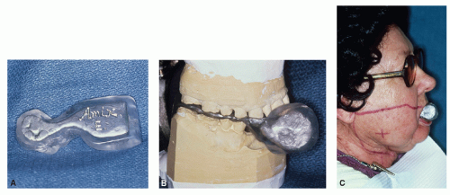 Figure 3.4 A 66-year-old woman presented with a right buccal mucosa lesion. On physical examination, she was found to have an infiltrative tumor measuring approximately 3.5 cm in largest diameter, extending anteriorly almost to the oral commissure. The tumor was 1.0 to 1.5 cm thick, without apparent skin involvement. There were two right submandibular nodes palpable, the largest measuring 2 cm in diameter. Biopsy revealed squamous cell carcinoma. The patient underwent resection of the tumor and a right modified neck dissection. Pathologic examination revealed a well-differentiated squamous cell carcinoma of the buccal mucosa with microscopic extension into the skeletal muscle and skin of the cheek. Nine lymph nodes were recovered in the surgical specimen, four of which contained metastatic squamous cell carcinoma with extension beyond the capsule. The patient received postoperative radiotherapy. The tumor bed and right upper neck were subjected to an ipsilateral appositional 13-MeV electron field to a given dose of 60 Gy in 30 fractions. The ipsilateral mid and lower jugular nodes and the posterior cervical chain were encompassed by a 9-MeV electron field. These areas were treated to a given dose of 50 Gy in 25 fractions. The scar extending into the mid neck was given a 4-Gy boost with 6-MeV electrons. A variation of the stent as described in Figure 3.3 was used for this patient. As in the previous case, the stent-containing cerrobend was placed between the alveolar processes and the tongue, serving to displace the tongue and to shield the tongue and contralateral oral mucosa. In this case, the right oral commissure needed to be included in the field and, therefore, fall off was required anteriorly. The stent protruded anteriorly to shield the contralateral part of both lips and the left oral commissure. A: Lateral view. B: Stent mounted on an articulator. C: Anterior end of the stent protrudes through the mouth for shielding part of the lips and the left oral commissure. (From Kaanders JHAM, et al. Devices valuable in head and neck radiotherapy. Int J Radiat Oncol Bio Phys 1992;23:639-645.) |
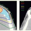
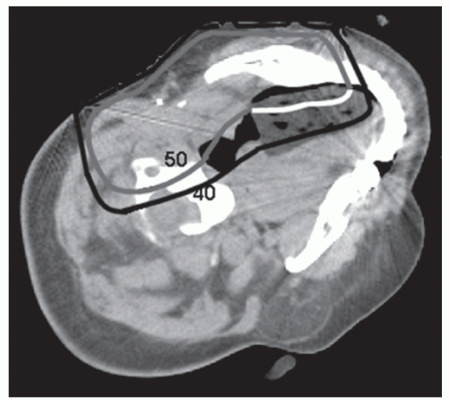 Figure 3.5 Axial computed tomographic (CT) scan images of patient with parotid carcinoma treated with an appositional 16-MeV electron field. A dose of 50 Gy was prescribed to the 90% line. To avoid artifact, a wax pattern of the stent was used for obtaining CT scan images. The stent captures the 50-Gy line at the edge of where the lateral tongue would normally be positioned. Without the stent, the 40-Gy line would have penetrated to the midline of the oral tongue. |
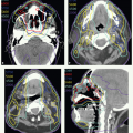
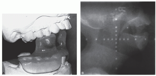 Figure 3.6 A 49-year-old woman presented with a 3-month history of enlarging neck masses. On examination, she was found to have a 3-cm exophytic lesion on the left side of the tongue base, extending laterally to the glossopharyngeal sulcus. Mobility of the tongue was normal. There were three palpable nodes in the neck (a 3.5 × 3 cm right upper jugular node, a 2.5 × 2 cm left jugulodigastric node, and a 2 × 2 cm left mid-jugular node). Biopsy of the primary lesion revealed squamous cell carcinoma. The patient received radiotherapy followed by neck dissection. The primary tumor and upper neck nodes were treated with lateral parallel-opposed portals with 6-MV photons to a dose of 45 Gy in 25 fractions, delivered to the isocenter. Reduction of the spinal cord was made and therapy was continued to a tumor dose of 54 Gy in 30 fractions. The posterior cervical strips were supplemented with electron beams. The mid and lower jugular nodes were treated through an anterior appositional field and were supplemented with a smaller posterior field to a tumor dose of 54 Gy in 30 fractions. During the last 2.5 weeks of this basic treatment, the primary tumor and palpable nodes were boosted to a total tumor dose of 72 Gy. The boost was delivered in 1.5 Gy per fraction, given as second daily treatments using the concomitant boost technique. The stent for this patient consisted of a horizontal tongue positioner with protrusions fitting the occlusal surfaces of the mandibular and maxillary teeth, which served to separate the upper and lower jaws. The horizontal portion depressed the tongue so that it could be treated with adequate margins without encompassing the hard palate, upper gums, and most of the buccal mucosa. A: Stent mounted on maxillary and mandibular casts. B: Portal film showing the position of the tongue held down by the depressor and the mouth kept open by the stent so that the palate, gum, and most of the buccal mucosa were excluded from the field. (From Kaanders JHAM, et al. Devices valuable in head and neck radiotherapy. Int J Radiat Oncol Bio Phys 1992;23:639-645.) |
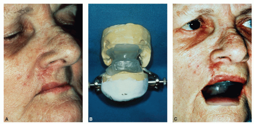 Figure 3.7 A 76-year-old woman presented with a lesion on the right side of the upper lip. On examination there was a slightly raised, erythematous lesion extending from the vermilion of the upper lip to the nasal ala with upward retraction of the lip (A). The lesion was 2.2 cm in largest dimension and involved almost the entire thickness of the lip. The inner mucosal lining was, however, intact. There were no palpable lymph nodes in the neck. A biopsy of this lesion showed basal cell carcinoma of which the patient received radiation therapy through an appositional 9-MeV electron field, which encompassed the tumor and a 1-cm margin of normal tissue. A lead cutout was used for skin collimation and a bolus of 1-cm thickness was placed over the skin to ensure an adequate dose at the surface of the tumor. Also, a bolus was placed in the right nostril to enhance the dose homogeneity. A dose of 50 Gy was given in 25 fractions, specified at the 90% isodose line, which was followed by an implant with radium needles. A stent was placed over the upper and lower alveolar processes to open the mouth and separate the lips, thereby excluding the lower lip from the radiation field (B,C). It also displaced the tongue posteriorly so that it was out of the range of the electron beam. To shield the gum, the part of the stent that was between the upper lip and the alveolar ridge was filled with Cerrobend. Acrylic coating prevents overdosage to the mucosa of the upper lip by backscatter. At the completion of electron beam treatment, confluent mucositis occurred at the upper lip mucosa, whereas no appreciable reaction was observed on the mucosa of the gum. A: A woman with a slightly raised lesion extending from the vermilion of the upper lip to the nasal ala with upward retraction of the lip. B: The stent used mounted on an articulator. The upper part of the stent that separated the upper lip from the alveolar process contained Cerrobend to shield the latter. C: The stent in treatment position. The lower flange held the lower lip away from the radiation field. (From Kaanders JHAM, et al. Devices valuable in head and neck radiotherapy. Int J Radiat Oncol Bio Phys 1992;23:639-645.) |
Related posts:

Stay updated, free articles. Join our Telegram channel

Full access? Get Clinical Tree


