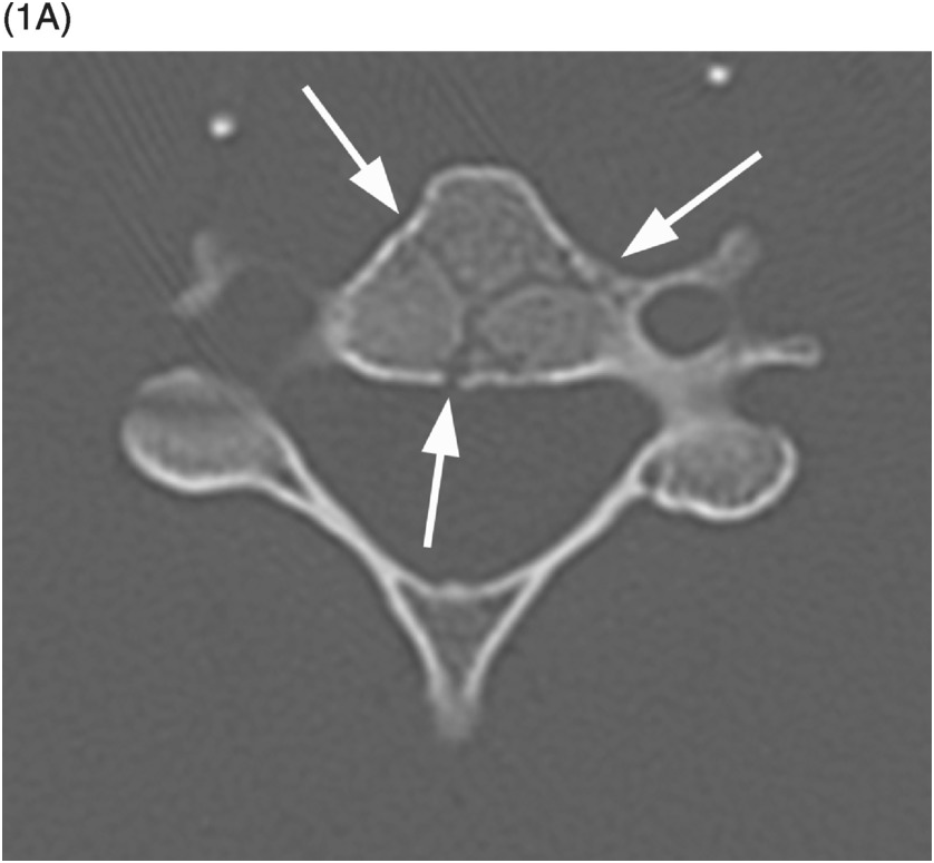
A) Axial CT image shows branching linear lucencies (arrows) at C5 vertebral body, which may potentially be concerning for fractures, although the curvilinear course is very typical for vascular channels. There is also a suggestion of sclerotic margins of the lucencies.
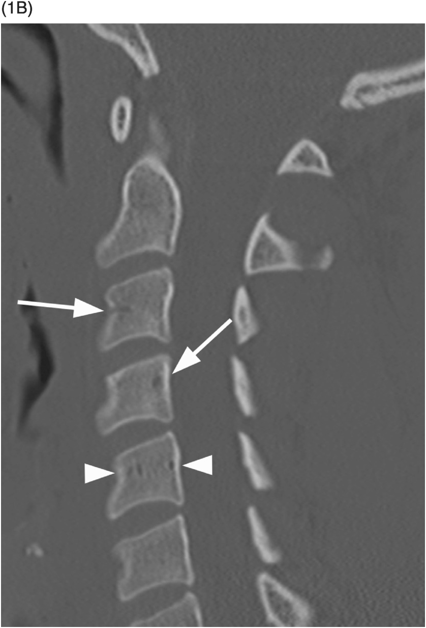
B) Reconstructed sagittal CT shows the C4 vascular channels as oval structures with well-corticated margins (arrowheads). Additional vascular channnels are present at C3 and C4 vertebral bodies (arrows).
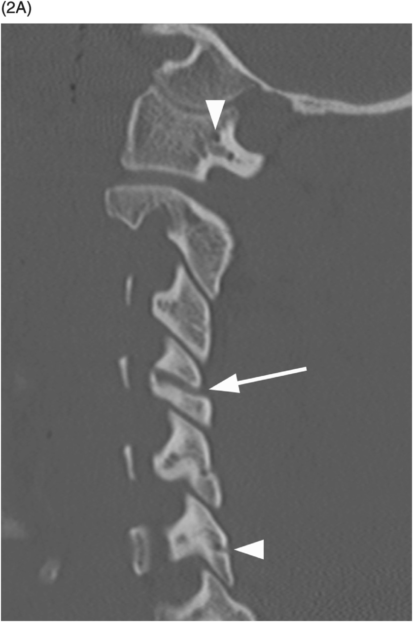
A) Sagittal CT image shows a probable vascular channel at C4 articular pillar (arrow). Note additional vascular grooves (arrowheads on some).
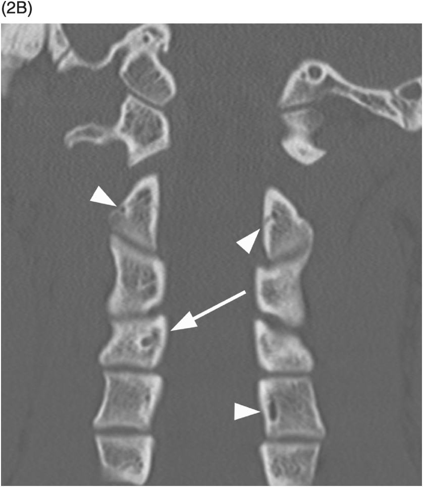
B) Coronal CT confirms sclerotic margins of the right C4 channel (arrow); multiple other grooves (arrowheads on some).
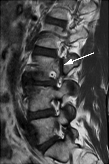
Figure 1.3 Sagittal T1-weighted MRI reveals a linear corticated defect (arrow) at L3 pedicle, consistent with a retrosomatic cleft.
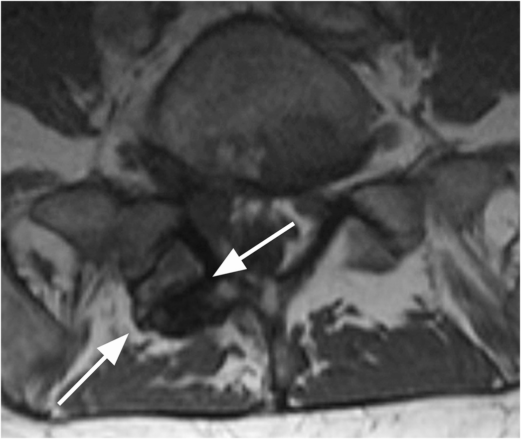
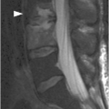
Figure 1.4 Axial T1-weighted MRI in a different patient shows a linear defect of the right lamina (arrows) with some bony overgrowth – a retroisthmic cleft.
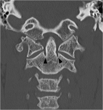
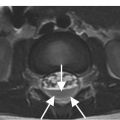
Figure 1.5 Coronal CT image demonstrates bilateral indentations (arrowheads) at the base of the axis, on either side of the dens with well-corticated margins. The findigs are consistents with bilateral clefts, a developmental variant.
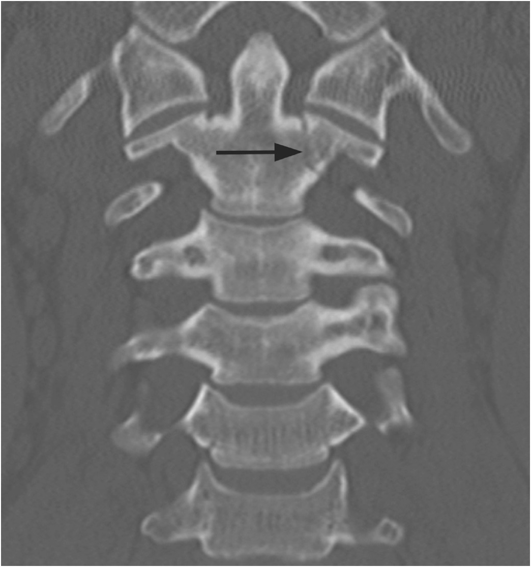
Figure 1.6 Coronal CT image in another patient shows shallow bilateral clefts along the superior aspect of C2 body; the one on the left extends through the body in a curvilinear fashion (arrow), consistent with a vascular channel.
Imaging Findings
Modern multidetector CT scanners frequently reveal the vertebral vasculature perforating through the cortical surface of the vertebral body and other parts of the vertebrae. These vascular (also known as nutritive) channels may simulate fracture lines, with which they may occasionally be confused. Careful review of images reconstructed in different planes typically allows identification of their characteristic vascular course, round to oval appearance on images that are perpendicular to their long axis, and their sclerotic margins.
Clefts at the base of the dens, which are remnants of a synchondrosis, may have similar appearance. They are commonly bilateral, but may also be unilateral, potentially simulating a fracture.
Clefts may occur at several locations within the more inferior vertebrae, most commonly through the spinous process (spina bifida occulta), resulting from failed osseous fusion of the posterior synchondrosis. A cleft may also occur within the pars interarticularis (spondylolysis), pedicle (retrosomatic cleft), or lamina (retroisthmic cleft). The characteristic location, sclerotic margins, and associated degenerative changes are typical features that allow distinction from acute fractures.
Differential Diagnosis
Acute Nondisplaced Fracture
Straight, sometimes irregular lucent lines, without sclerotic margins, typically extending through the entire bone, without rounded appearance on images perpendicular to their long axis.
Chronic Fracture
Typically straight lines with corticated margins, usually extending through the entire bone, without rounded appearance on images perpendicular to their long axis.
Clinical Findings, Implications, and Treatment
Vascular channels are normal findings and therefore do not require any treatment. Their identification may at times be difficult, typically due to presence motion or streak artifacts. In these cases, repeat focused CT of the area in question, possibly with a different technique (removal of any metallic foreign bodies, lower positioning of the shoulders/arms down, increased kVp), may be needed. Absence of bone marrow edema on MRI is also reassuring.
Additional Information
Increasing quality and decreasing slice thickness of CT scans over time has led to improved identification of anatomic details, including normal variants, especially with high-resolution isotropic images reconstructed in three or more planes. As with other anatomical structures and clinical settings, this allows for better detection of pathological processes but, at the same time, may also be responsible for an increase in false-positive findings, since various anatomic variants are now visualized more and more frequently.
Retrosomatic and retroisthmic clefts are far less common than spondylolysis (pars interarticularis defect). The cause of these clefts is unclear; they may be associated with repetitive stress and should be differentiated from acute fractures.
References
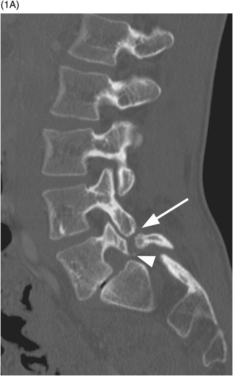
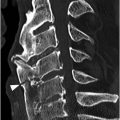
A) Sagittal CT image shows spondylolisthesis of L5 with pars interarticularis defect (arrow). A bony element is filling the pars defect (Gill’s nodule, arrowhead).
B) On the axial CT image the bilateral pars defects can be differentiated from the adjacent facet joints (arrowheads) by the more anterior location, more irregular contours, and sclerotic margins. A Gill’s nodule is well seen (arrow).
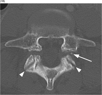
A) Sagittal T1-weighted image demonstrates a defect of the pars interarticularis involving L3 vertebra with sclerotic margins.
B) STIR image reveals that the L3 pars defect is filled high signal intensity (arrow), consistent with fluid/inflammatory tissue.

Imaging Findings
Spondylolysis refers to the radiolucent defect in the pars interarticularis. Multiple signs of spondylolysis have been described on radiographs, including lateral deviation of the spinous process, sclerosis of the contralateral pedicle, and the lucency at the neck of the “Scotty dog” on the oblique views. On axial CT scans at the level of the pedicles, discontinuity of the neural arch indicates a pars defect (“incomplete ring sign”). Pars defects are differentiated from the adjacent facet joints by their more irregular contours and sclerotic margins. If spondylolisthesis coexists, the axial scan also depicts the widened sagittal diameter of the spinal canal. In spondylolytic spondylolisthesis, the spinous process step-off is at the level above the pars defect on the sagittal images, in contrast to degenerative spondylolisthesis in which forward displacement of the vertebra is at the same level with the spinous process, with associated narrowing of the spinal canal. Sagittal CT images are also the most accurate in showing fractures, even incomplete, usually located in the infero-medial cortex of the pars. CT may depict bony elements in or adjacent to the fibrous or fibrocartilaginous tissue filling the pars defect (Gill’s nodules). Axial CT and MRI images also show “continuous” or “endless” appearance of the facet joints when scrolling through the adjacent levels, without presence of intact laminae in between the joints.
On MRI, the pars defect appears as an interruption of the cortex and marrow through the pars, best seen on T1-weighted images. If there is also a gap at the site of the lysis, the signal intensity of the tissue filling the defect varies: low on T1- and T2-weighted images when composed of fibrous tissue, or high on T2-weighted sequences due to the presence of inflammatory tissue or fluid. Recognition of an incomplete fracture and of spondylosis without spondylolisthesis is the main challenge for MRI; ancillary findings may help the diagnosis, such as the widened sagittal diameter of the spinal canal, wedging of the posterior aspect of the vertebral body at the level of the spondylolysis, location of the step-off, and reactive marrow changes in the pedicles adjacent to a pars defect. In case of spondylolisthesis, MRI can also demonstrate the radicular stretching linked to the displacement of the slipping vertebra and rule out other causes of nerve root compression. Fat suppressed sagittal oblique VIBE T1-weighted sequence may have higher sensitivity for the diagnosis of spondylolysis.
Differential Diagnosis
Acute Fracture
Lucent fracture line is without sclerotic margins, sometimes irregular.
Clinical Findings, Implications, and Treatment
Most cases of spondylolysis are completely asymptomatic or characterized by notable discrepancy between clinical and radiological findings. The most common finding on physical examination is a hyperlordotic curvature. Symptomatic patients usually complain of mechanical-type low back pain, worsened by activity (particularly flexion–extension) and improved with rest. Radicular symptoms are less common, especially in young patients. The treatment for spondylolysis and spondylolisthesis is initially conservative and aims to reduce pain and facilitates healing; surgical treatment is generally reserved for patients who fail to respond to conservative management.
Additional Information
The pathogenesis remains controversial and several observations favor a hereditary predisposition. Pars defect may also be an acquired stress fracture secondary to chronic low-grade trauma, rarely following acute trauma. Developmental factors, such as posture or certain repetitive physical activities, may lead to a stress fracture of the pars interarticularis. The most probable mechanism of lumbar spondylolysis is multifactorial with a stress fracture occurring through a congenitally weak or dysplastic pars interarticularis. Pars defect almost always occurs bilaterally and involves the L5 vertebra in 95% of cases. The incidence progressively decreases in a cephalad direction.
References

Figure 3.1 Axial CT image of C1 in a 19-month-old female shows 3 separate ossification centers of the atlas: 1 anterior central arch and 2 posterior neural arches. The posterior synchondrosis should fuse first between the ages of 3 to 5 years. The synchondroses anteriorly usually fuse between 5 and 8 years of age.

Figure 3.2 Axial CT image in an adult patient imaged for trauma. There is non-fusion at the midline of C1 anteriorly and posteriorly. Note the well-corticated margins anteriorly and posteriorly and slight hypertrophy of bone at the anterior non-fusion. The posterior midline type of non-fusion is more common.

Figure 3.3 Axial CT image obtained in a 48-year-old man with neck pain and temporary loss of consciousness after an MVC. There are defects of the posterior lateral aspect of the arch of C1 bilaterally with non-corticated margins and slight widening on the left. These are bilateral posterior arch fractures of C1. Contrast these with the midline well-corticated defect (arrow), which is a typical midline non-fusion variant.

Figure 3.4 Axial CT image in a 23-year-old with altered mental status after an MVC. There is posterior lateral non-fusion of right arch of C1 with tapered apposing margins of the bone (arrow). There is mild secondary hypertrophy and sclerosis of the left posterior arch (arrowhead). This unusual variant is secondary to a dysplasia of the right posterior neural arch, which may be secondary to injury during development.
Imaging Findings
Differentiation of a non-fusion variant of C1 from a fracture is dependent on knowledge of their occurence and recognition of their well-corticated appearance when compared to fractures. The most common site of non-fusion of C1 is at the posterior midline occuring in 3–4% of patients. Non-fused posterior clefts may also be located slightly off the midline unilaterally or bilaterally. Anterior C1 non-fusion is substantially less common than the posterior form; these clefts are typically also at or just off the midline. However, variant clefts may be found anywhere around the C1 ring. In more extreme variant forms, dysplasia of 1 of the 3 normal ossification centers may present with a wider irregular but corticated defect.
Differential Diagnosis
C1 (Jefferson) Fracture
Irregular fracture lines without corticated margins.
Post-operative Bone Defect
Bone defect with straight lines, sclerotic margins are not formed yet following recent surgery.
Clinical Findings, Implications, and Treatment
True anatomic variants are essentially always unrelated to the patient’s injury or reason for CT or MR examination. However, in some cases, well-corticated defects that are secondary to old injury may be confused with normal variation. C1 fractures in skeletally immature patients may have a delayed presentation after minor injury with pain and torticollis. If missed initially, these fractures may do well with conservative or no treatment and mimic a variant on a later exam. In the uncommon situation that a variant could not be distinguished from acute fracture, MRI may show a lack of adjacent soft tissue and bone marrow edema or ligamentous injury.
There are rare case reports of instability or neurologic deficit after minor injury related to preexisting variant C1 fusion defects. Associated symptoms in these case reports have generally been transient. Evaluation in these patients would include flexion-extension radiography, when clinically appropriate. A majority of true C1 fractures are treated conservatively in a collar.
Related posts:

Stay updated, free articles. Join our Telegram channel

Full access? Get Clinical Tree


