Shear Wave Elastography
4.1 Overview
A second technique to determine the elastic properties of a tissue is shear wave velocity measurement.5,20,21,22,50,51,52,53 In this technique an initial ultrasound pulse (push pulse) applied to the tissue induces a shear wave perpendicular to the ultrasound beam. The velocity of the shear wave generated through the tissues may be calculated using standard B-mode ultrasound sampling techniques (▶ Fig. 4.1). From the velocity of the shear wave through the tissues the strain (Young) modulus can be estimated. The velocity of the shear wave is proportional to the tissue stiffness. The stiffness of a lesion can be displayed as the shear wave velocity (Vs in m/s) or the strain modulus (expressed in kPa).

Fig. 4.1 The shear wave velocity is calculated using B-mode scanning to monitor the shear wave movement through tissue. This diagram depicts the process. (A) The acoustic radiation force impulse (ARFI) that generates the shear wave. (B) The area that is monitored by B-mode imaging to monitor the tissue movement caused by the shear wave. (C) The curves that are identified by plotting the tissue displacement at a given location over time. (D) The slope of the line by plotting the time of the maximum tissue displacement at the different locations from the ARFI pulse is the shear wave velocity.
With shear wave elastography (SWE) a quantitative measure of the lesion stiffness is obtained either in a region of interest (ROI), point quantification SWE (pSWE) or pixel-by-pixel using a color map, 2-D SWE. Examples of a benign and malignant lesion are presented in ▶ Fig. 4.2 and ▶ Fig. 4.3.

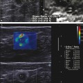
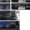
Fig. 4.2 Shear wave elastography images use a color overlay on the B-mode image to provide the shear wave velocity (Vs) in m/s (or estimated Young modulus in kPa) for each pixel in the field of view. Some systems also provide a B-mode image in a dual display. In this case the elastogram overlaid on B-mode image is the upper image, whereas the B-mode image is the lower image. The white square is the region of interest (ROI) where shear wave imaging was performed. Opposed to strain imaging, the color coding here corresponds to quantitative measurements that can be used to characterize a breast lesion. In this case of an invasive ductal carcinoma the Vs values are elevated in the malignancy to a maximum Vs of 6.3 m/s (118 kPa) and 2.2 m/s (15kPa) suggestive of a malignancy. When an ROI is placed over the area of interest the maximum, minimum, mean, and standard deviation of the pixels in the ROI is displayed.

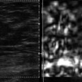
Fig. 4.3 In this case of a benign fibroadenoma the lesion color codes soft with a maximum Vs of 2.7 m/s (22 kPa) suggestive of a benign lesion.
Precompression can markedly change values.19 ▶ Fig. 4.4 and ▶ Fig. 4.5 demonstrate the effect of precompression on both a benign and a malignant lesion. Note that with precompression even a benign lesion can have high Vs suggestive of a malignant lesion. Precompression will also increase the Vs surrounding a malignant lesion. The technique to apply only minimal precompression described in Chapter ▶ 3 is recommended to limit this effect.19

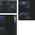
Fig. 4.4 The effect of increased precompression can significantly change the shear wave elastography (SWE) results. In this figure the SWE of a simple cyst is presented with increasing amounts of precompression. Note that rib (arrow) in the far field is located closer to the transducer as precompression is added. With moderate precompression a benign lesion can have Vs values suggestive of a malignancy.
(Reprinted with permission from Barr RG, Zhang Z. Effects of precompression on elasticity imaging of the breast: development of a clinically useful semiquantitative method of precompression assessment. J Ultrasound Med 2012;31(6):895–902)

Fig. 4.5 The same effects of precompression can be seen with a malignant lesion. This figure demonstrates the effect of increasing precompression on an invasive ductal cancer. The arrow points to a ligament. Notice that as precompression is added the ligament is located closer to the transducer. Note that as precompression is added a ring of high Vs is created at the lesion/normal tissue interface.
(Reprinted with permission from Barr RG, Zhang Z. Effects of precompression on elasticity imaging of the breast: development of a clinically useful semiquantitative method of precompression assessment. J Ultrasound Med 2012;31(6):895–902)
4.2 Technique/How to Perform an Examination
In SWE an initial ultrasound pulse (push pulse, also referred to as the acoustic radiation force impulse [ARFI]) is applied to the tissue that induces a shear waves perpendicular to the ultrasound pulse. Shear waves are similar to dropping a stone in a pond (analogous to a push pulse) and ripples will occur (analogous to shear waves). Using ultrasound B-mode sampling techniques, the velocity of the shear wave generated through the tissues can be calculated. From the velocity of the shear wave in the tissue, the Young modulus can be estimated using some assumptions (see Chapter ▶ 2). The velocity of the shear waves is proportional to the stiffness. The stiffness of a lesion can be displayed as the shear wave velocity (Vs) in m/s through the tissue, the shear modulus, or the Young modulus in kilopascals (kPa). Both systems allow you to obtain either measurement or convert from one to the other on the system.
The principles of scanning technique using strain elastography (SE) also pertain to SWE. Maintaining the same location of the lesion with no movement is important to obtain accurate results. After the ARFI pulse is applied data acquisition occurs for a short period of time. During the data acquisition period the movement of the shear wave is monitored by B-mode imaging. If there is tissue movement caused by movement of the transducer or the patient the system will interpret this non–shear wave movement in the calculation of Vs. For more accurate measurements, patients must hold still and hold their breath.
Precompression can change results, and we recommend the same technique discussed in Chapter ▶ 3 be used to acquire images using shear wave technology. As previously discussed the shear wave speed of fat in the breast can be changed by a factor of 10 with precompression, therefore it is important not to compress the tissue with the transducer. SWE on one system can be performed in real time; however, to obtain adequate measurements and optimal images one must remain in the same plane for several seconds. Shear wave generation is depth limited, and, depending on tissue density, if a lesion is deeper than 4 to 5 cm a result may not be obtained. It may help to reposition the patient and bring the ROI closer to the transducer. If there is no shear wave generation, no color coding will occur in this area. With SWE a quantitative measure of the lesion stiffness can be obtained either in a small fixed ROI (point quantification) or pixel by pixel in a field of view (FOV) using a color map (shear wave imaging). The results are color coded, usually with a convention of red as hard and blue as soft.
Two shear wave systems are presently available. In the S2000 and S3000 system (Siemens Ultrasound, Mountain View, CA), either a measurement in a small ROI can be obtained (Virtual Touch tissue quantification [VTq]) or a pixel-by-pixel evaluation can be made of a larger FOV using a color map (Virtual Touch IQ [VTIQ]). In VTIQ after the initial push pulse, tracking signal vectors are used to detect the tissue displacement as the shear wave passes and thus reconstruct its velocity in a region of interest, which can be displayed as a quantitative image displayed as shear wave velocity. With this technique a single image is obtained. The tracking vectors with focused transmit results in less noisy and more stable shear wave signal detection. This system obtains one image and the system is frozen for a few seconds do to the power output.
The second shear wave system, the Aixplorer (SuperSonic Imagine [SSI], Aix en Provence, France) uses rapid sequence of ARFI pulses that generates a mach wave and measures the sear wave velocity over a wide FOV. The system operates in real-time, but the probe needs to be held steady over a lesion for several seconds to get an accurate shear wave measurement. The system color codes the pixels within the FOV with the shear wave velocities or kPa. Multiple ROIs can be placed in FOV to measure the shear wave velocities at various locations.
Related posts:

Stay updated, free articles. Join our Telegram channel

Full access? Get Clinical Tree


