3 Shoulder As a ball-and-socket joint, the shoulder is a common site of chronic complaints. It is not unusual for the shoulder pain in young athletes to have no corresponding radiographic changes. The clinical evaluation can be complemented by a variety of imaging procedures, among which MRI has evolved as a procedure of high diagnostic value. This increasing role for MRI of the shoulder has been well documented in numerous review papers (3, 21, 27, 33, 49, 56, 58, 63, 68). This chapter will present the anatomy and pathologic changes as displayed by MRI as well as the role of MRI in the diagnostic evaluation of the shoulder joint. The patient is examined supine in the head first position. The patient should rest comfortably to reduce motion artifacts during the examination. A generous use of supporting pillows and other means can be helpful. To avoid respiratory artifacts, the arm to be examined should not be placed on the abdomen. It should be kept in external rotation or a neutral position. Internal rotation should be avoided since it overlaps the tendons of the rotator cuff and surrounding soft tissues, making assessment difficult and potentially leading to misinterpretations (9). The shoulder to be examined can be stabilized with sand bags to avoid minor movements. Suppression of respiratory artifacts is generally unnecessary. For patients with very broad shoulders, it may be necessary to position the patient obliquely by elevating the opposite shoulder. This will move the side in question toward the isocenter of the magnetic field and improve the image quality. To achieve an adequate signal, the shoulder is examined with a surface coil. A flexible or a rigid ring coil has proved useful. Rectangular coils can be used as well. The imaging protocol should begin with fast T1- weighted images in the coronal plane (SE), using a large field of view (FOV) and a body coil. These images serve as a pilot view to compare the distribution of the bone marrow signal between both sides and to select the appropriate high resolution sequences for the symptomatic shoulder. The first high resolution sequence is performed in the axial plane. It is important to assure an adequate resolution and the inclusion of the acromioclavicular articulation. To achieve an optimal resolution, the FOV should be confined to the area to be examined, as necessary for all high-resolution MRI examinations, and should be between 140 and 180 mm2. Because of the signal-to-noise ratio, this measurement is determined by the magnetic field strength of the MR system. The section thickness should not exceed 4 mm. Based on theoretical and practical considerations, a dual echo steady state GRE sequence with an in-phase first echo has proved useful (57). The first short echo produces a good anatomic visualization and the second later echo the desired T2 or T2* weighting (see Chapter 1). Axial images are best suited for disease processes of the glenoid labrum and the long biceps tendon. The images obtained with these sequences through the supraspinatus muscle are used to plan both subsequent sequences (Fig. 3.1), an oblique coronal T1-weighted SE sequence and an oblique coronal dual echo steady state GRE sequence. This plane is at an angle of about 45 degrees to the coronal plane and consequently parallel to the main orientation of the supraspinatus muscle. It is the only plane that requires a T1-weighted sequence. The SE sequence facilitates the detection of susceptibility artifacts and hemorrhage as well as bone marrow infiltrates. Oblique coronal images are best suited for the evaluation of the rotator cuff and the subacromialsubdeltoid bursa. The examination is completed with a dual echo steady state GRE sequence in the oblique sagittal plane. This plane is perpendicular to the oblique coronal plane and suitable for the evaluation of the outer rotator cuff and the supraspinatus outlet. Fig. 3.1 Transverse schematic drawing of the shoulder illustrating the oblique sagittal and oblique coronal planes. When evaluating the bone marrow for edema or tumor infiltration, a STIR sequence or possibly a fast STIR (FSTIR) should be added. These sequences have the benefit of additive T1 and T2 contrast as well as the visualization of fat against a background void of any signal and therefore are extremely sensitive to the detection of intramedullary processes (see Chapter 1). Fat suppression. This can improve the delineation of the tendons or capsular structures of the shoulder (34). It reduces artifacts caused by chemical shift and eliminates interference from adjacent fat-containing tissues and tendons or musculature. The clinical routine has proved that the sensitivity of detecting soft tissue lesions is not higher in comparison with T2*-weighted GRE sequences and that fat suppression does not have to be used routinely (57). Acquisition of a three-dimensional data set. The acquisition of a three-dimensional data set with subsequent multiplanar reformatting has been advocated. In some circumstances, where an isotropic data set has been obtained, the multiplanar reformatting allows visualization of anatomical structures such as the coracoacromial ligament that may not be well seen on standard sections. However, the use of these sequences needs to balanced by some limitations. The contrast comprises a mixed weighting of T1 over T2 if the three-dimensional steady state GRE sequence with short TR and TE is employed. This lacks important criteria for image interpretation, such as the signal pattern of T1 and T2 weighting, and can result in interpretative errors. Moreover, the resolution of the reformatted sections is only identical with the original data set if it is isotropic (see Chapter 1). Generating a high resolution isotropic data set of the shoulders is very time consuming and, in the end, no time saving is achieved in comparison with conventional methods because of the additional long reconstruction times. Further disadvantages include the vulnerability of GRE sequences to magnetic field heterogeneity and to susceptibility effects such as those seen between trabecular bone and adjacent bone marrow. GRE sequences are also more vulnerable to magic angle effects because of the need to employ a short TE. This may lead to the false positive diagnosis of rotator cuff pathology (see below). Special methods. Special methods, such as the radial sequence with its radial rather than parallel acquisition of the planes (37), or the three-dimensional (3-D-rendering), which is even more time consuming, have not proved useful in routine clinical application. ABER position. The ABER position refers to the position of the patient’s arm, which is placed in AB ducted and E xternal R otation. This is achieved by placing the patient’s hand behind the head. Sections are then obtained in an oblique axial plane aligning them with the long axis of the humerus on a coronal localizer. Several advantages have been found with the use of this technique. The undersurface of the supra- and infraspinatus tendons is well shown and visualization of subtle undersurface tears is improved. Furthermore, the technique has been found to be helpful in visualizing the anteroinferior glenoid labrum and associated inferior glenohumeral ligament which is under tension in this position. The evaluation of these structures is important when assessing the shoulder for causes of instability since they act as important static stabilizers of the joint (54 a). MR arthrography. This can markedly improve the detection rate of partial tears of the articular surface of the rotator cuff, in particular with the aid of fat suppression (20, 45). Furthermore, diagnosing lesions of the glenoid labrum can be improved by MR arthrography (14, 46). This is performed by injecting 10 – 15 ml of a 1: 250 diluted Gd-DTPA solution (corresponding to 0.002 mmol/ml Gd-DTPA) into the joint, followed by T1-weighted imaging with fat suppression. While this technique has the disadvantage of converting a non-invasive procedure into an invasive one, many centers now feel that the advantages justify its use. This is particularly the case for the investigation of shoulder instability in younger patients where labral abnormalities are suspected. In such cases MR arthrography may be the investigation of choice. In older patients, where chronic instability generally results from a different pattern of underlying abnormality, or where rotator cuff lesions are the primary concern, conventional MRI is probably adequate. This technique may be combined with the ABER position described above. Indirect MR arthrography following intravenous injection and joint movements can be seen as an alternative (27 a, 56 b, 65 a) (see Chapter 1). Cinematic examination. This method is feasible with fast GRE sequences. Clinical applications have not yet been established (5). In the shoulder girdle, humerus and scapula articulate, forming the glenohumeral joint, as well as acromion and clavicle, forming the acromioclavicular joint. The articular surface of the glenoid fossa covers only one-third of the articular surface of the humerus. The area of contact is extended by a fibrocartilaginous rim (glenoid labrum). The joint capsule is reinforced anteriorly by the three glenohumeral ligaments (superior, middle, and inferior). Two variable outpouchings of the joint capsule above and below the middle glenohumeral ligament are known as the superior and inferior subscapular recesses. The joint is surrounded by a fibrous envelope formed by the tendons of four muscles (rotator cuff). The multigastric subscapularis passes anteriorly, the digastric supraspinatus superiorly, and infraspinatus and teres minor posteriorly. It has only been discovered recently, partly by MRI, that the supraspinatus muscle consists of two parts (Fig. 3.5) (61). The spatial relationship of the supraspinatus muscle to the surrounding tissues is of great importance for pathologic alterations of the rotator cuff. The undersurface of the acromion, the coracoacromial ligament and acromioclavicular joint form the supraspinatus outlet or coracoacromial arch (39). The proximal tendon of the long head of biceps has a complex and variable insertion. The insertion sites include the superior glenoid tubercle and superior glenoid labrum. Fibrous slips also extend to the posterior and anterior labrum and the joint capsule. The tendon curves anteriorly through the joint to the intertubercular sulcus of the humerus where it is enclosed by a tendon sheath. The short head of the biceps arises from the coracoid apex together with the coracobrachialis. The subacromial-subdeltoid bursa lies superficial to the rotator cuff beneath the acromioclavicular joint and the deltoid muscle. It does not normally communicate with the glenohumeral joint. It is the largest bursa of the body and consists of a subacromial compartment and a subdeltoid compartment, which are demarcated by an indentation. In 10% of the cases, the subacromial-subdeltoid bursa communicates beneath the coracoid process with the subcoracoid bursa. A wedge-shape intra-articular disk projects into the acromioclavicular joint from the upper part of the articular capsule. Fig. 3.2a–c Anatomy of the shoulder. Transverse section. GRE sequence (0.5 T, TR = 600 msec, TE = 14 msec, flip angle = 30 degrees).
Introduction
Examination Technique
 Patient Positioning
 Surface Coil
 Sequences and Parameters

 Special Examination Techniques
Anatomy
 General Anatomy


Axial | Oblique coronal | Oblique sagittal |
Supraspinatus muscle | Supraspinatus tendon | Rotator cuff |
Glenoid labrum | Infraspinatus tendon | Coracoacromial ligament |
Joint capsule | Subacromial bursa | Acromion |
Glenohumeral ligaments | Acromioclavicular joint |
|
Biceps tendon | Superior labrum and biceps anchor |
|
 Specific MR Anatomy and Variants
Figs. 3.2–3.4 illustrate the most important structures of the shoulder in the three imaging planes: axial, oblique coronal, and oblique sagittal. Table 3.1 assigns the relevant anatomic structures to the plane most suitable for their visualization.
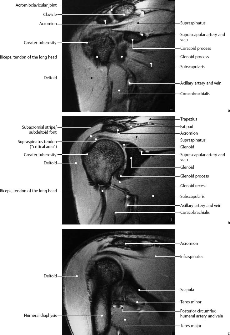
Fig. 3.3a–c Anatomy of the shoulder. Oblique coronal section. GRE sequence (1.5 T, TR = 550 msec, TE = 15 msec, flip angle = 30 degrees).

Fig. 3.4a–c Anatomy of the shoulder. Oblique sagittal section. GRE sequence (1.5 T, TR = 550 msec, TE = 9 msec, flip angle = 30 degrees).
Axial plane. The supraspinatus muscle, which runs at an approximate 40 degree angle to the coronal plane, is well delineated on the axial plane (Fig 3.2). The centrally located tendon accepts fibers of the anterior and posterior muscle belly and assumes an eccentric course at an angle of 50 degrees within the muscle fibers (Fig. 3.5). Both muscle bellies as well as the eccentric strong tendon insert at the greater tuberosity. In more than 80% of the cases, the central tendon also inserts at the lesser tuberosity as well as at the intertubercular ligament (61). Identifying the supraspinatus muscle serves to set up the oblique coronal and oblique sagittal sections. It does not matter whether a 40 or 50 degree angulation is selected for the oblique coronal sections (60). The subscapularis is best shown in this plane.
The axial sections delineate the anterior and posterior glenoid labrum well as low-signal, structures. They cap the cortical surfaces of the scapula as well as the high-signal hyaline articular cartilage. The labrum can have numerous variants and may not be visualized in up to 8% of normal cases (31, 32, 41) (Fig. 3.6). The morphologic variants affect the anterior labrum. Anteriorly and posteriorly, the labrum usually has a triangular configuration, but variations in the shape are seen, the most frequent being a rounded appearance. The labral variants are predominantly observed in the upper anterior portion (up to 10% of the cases), where the labrum can be separated from the osseous glenoid fossa (the so-called sublabral foramen) or may be completely absent (partial labral aplasia). Either normal variant can be mistaken for a tear by arthroscopy or imaging (Fig. 3.7) (56 a). Areas of focal and linear increase in signal intensity have been described within the labrum of patients without known trauma or complaints This is in part explained by the magic angle effect seen in sections of the labrum orientated at 55 degrees to the main magnetic field. A similar effect is seen in the menisci of the knee. In addition, residual vascularization may account for this appearance. These signals should not be mistaken for a tear.
The joint capsule can be well evaluated on axial images. The insertion of the anterior capsule at the glenoid labrum is quite variable and can be classified into three types (52) (Figs. 3.8 and 3.45). A recess between scapula and anterior capsule should not hastily be interpreted as capsular separation. The diagnosis has to rest on the history and clinical examination. A proximal insertion at the scapular neck (type III) is considered a predisposition to an anterior shoulder dislocation. The anterior joint capsule is strengthened by three ligaments, the glenohumeral ligaments. They extend obliquely from the anterior glenoid margin to the humeral head. Between the ligaments are two openings of the joint capsule, which communicate with the superior and inferior subscapular recesses of the joint capsule. The superior glenohumeral ligament is small and thin and not always seen on MRI. The middle glenohumeral ligament is rather strong and is regularly delineated as a signal-free, band-like formation. Since it follows an oblique course relative to the axial plane, it is often only partially seen (Fig. 3.2b). A well described variant is a thickened, prominent middle glenohumeral ligament in combination with an attenuated or absent anterosuperior glenoid labrum. This is known as the Buford complex.

Fig. 3.5 Schematic drawing of the supraspinous fossa seen from above. The supraspinatus consists of two muscle bellies and has a central, eccentrically located tendon.

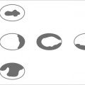
Fig. 3.6 Schematic drawing of the transverse section. Morphologic variants of the glenoid labrum with relative distribution in percentage for the anterior labrum. a triangular with line of increased signal intensity along the hyalin articular cartilage (50%). b rounded (20%). c comma-shaped flattened (7%). d absent (3%). e cleaved (15%). f notched (8%). g central increase in signal intensity. h linear increase in signal intensity. The posterior labrum generally exhibits a triangular or rounded form.

Fig. 3.7a–c Morphologic variants of the glenoid labrum in the upper anterior aspect. Left: orthograde view of the glenoid fossa with glenoid labrum and the three glenohumeral ligaments. Right: corresponding transverse MR images through the upper portion of the glenoid fossa (level marked by line on orthograde view). a Normal finding. b So-called sublabral foramen through the partially absent labral attachment to the glenoid fossa. c Partial labral aplasia. These normal variants should not be mistaken for labral avulsions.
The inferior glenohumeral ligament comprises an anterior and posterior band, with the axillary recess of the joint capsule arising between these two bands. The three glenohumeral ligaments actually represent thickenings of the anterior joint capsule. They usually arise from the anterior aspect of the glenoid including the labrum and are best seen when the joint capsule is distended with fluid, or at MR arthrography. In up to 15% of cases, variations are observed in the ligamentous anatomy. Additional oblique images obtained in the ABER position may assist in the visualization of the anteroinferior glenoid labrum and the inferior glenohumeral ligamentous complex. In this position the tension produced may distract an otherwise undetectable anterior labral tear (54 a).
The long biceps tendon as well as its sheath are also best assessed in the axial plane. The tendon extends through the glenohumeral joint as well as through the bicipital sulcus, an osseous groove in the anterior humeral shaft. Within the sulcus, the tendon is surrounded by a tendon sheath, which communicates with the joint. Anteriorly, the sulcus is covered by the transverse ligament. The tendon is seen as a round, signal-free structure in the intertuberculous sulcus. Even in healthy individuals, it can be surrounded by a small amount of fluid (23).

Fig. 3.8 Schematic drawing of the transverse plane. Variations in configuration of the scapular insertion of the anterior joint capsule. The capsule inserts at the base of the glenoid labrum in type I, more medially in type II and along the glenoid neck in type III. The type III capsular insertion predisposes the shoulder to dislocate and should not be mistaken for a traumatic capsular detachment. A traumatic detachment of the capsule can be mistaken for a type III capsular insertion.
Oblique coronal plane. This plane (Figs. 3.3 and 3.9) is well suited for evaluating the insertion of the supraspinatus muscle at the greater tuberosity. The fibroconnective tissue of the tendons is generally shown as low signal on all sequences. Pathologic changes are characterized by increased signal intensity, but an increase in signal intensity can be observed near the insertion of the supraspinatus tendon in 80% of the cases without further evidence of traumatic or degenerative alteration of the rotator cuff (Fig. 3.3b). This increased signal, which is especially conspicuous on T1-weighted and proton density images and characteristically does not further increase in intensity on T2–weighted images, may result from a variety of causes. The increased signal may be focal or linear in shape and has a superior, central or inferior location within the tendon (43). In some cases the appearance may represent early myxoid degeneration which may relate to the poor vascularity of this zone (the ‘critical zone’) (51). This appearance may be seen in asymptomatic young volunteers and is therefore presumably not age related. Other causes of this appearance include interposition of the tendon fibers with fat or connective tissue and partial volume averaging of adjacent muscle fibers (60). It is now recognized that in many cases this phenomenon is the result of the so-called ‘magic angle’ effect related to the orientation of the tendon in the main magnetic field (11).

Fig. 3.9 Oblique coronal plane.
1 = Acromion
2 = Supraspinatus tendon
3 = Inferior glenoid labrum
4 = Deltoid fat stripe
5 = Fat stripe of the subacromial-subdeltoid bursa
It is known that anisotropic tissues, such as hyaline or collagen fibers, change their relaxation times if their longitudinal microfibrils are at a certain angle to the magnetic field. This angle was found experimentally to be 55 degrees and is referred to as the magic angle. This phenomenon also explains signal abnormalities found in other tendons and cartilages without documented pathology (see Appendix, section 1).
Another important structure to be evaluated in the oblique coronal plane is the subacromial-subdeltoid bursa. The bursa itself is normally invisible, but it is surrounded by extrasynovial fat that is identifiable by MRI in up to 70% of cases. The thickness of this peribursal fat plane correlates positively with the patient’s age and weight and negatively with athletic activity and muscle mass (35). It is visualized as a stripe of high-signal intensity on T1-weighted images (Fig. 3.10). Displacement and obliteration of the fat stripe and fluid accumulation within the bursa can serve as diagnostic criteria for various diseases (59).
The acromioclavicular joint is also best evaluated in the oblique coronal plane. The position of the articular disk and the width of the joint capsule are clearly delineated. Changes of the acromioclavicular joint are relevant in context with the impingement syndrome of the supraspinatus muscle (62 a).

Fig. 3.10 Oblique coronal T1-weighted SE image with visualization of the fat stripe of the subacromial-subdeltoid bursa as line of high signal (arrow). (0.5 T, TR = 600 msec, TE = 20 msec).

Fig. 3.11 Schematic drawing of the shoulder in the oblique coronal plane corresponding to Fig. 3.4b.
1 = Acromion
2 = Supraspinatus muscle
3 = Infraspinatus muscle
4 = Teres minor muscle
5 = Inferior glenohumeral ligament
6 = Middle glenohumeral ligament
7 = Subscapularis muscle
8 = Long biceps tendon
10 = Coracoid process
11 = Coracoacromial ligament

Fig. 3.12 a–d Variants of the acromial attachment of the coracoacromial ligament. a Attachment at the tip of the acromion (approximately 10%). b Attachment at the base and undersurface of the acromion (approximately 20%). c Attachment at the base of the acromion (approximately 50%). d Attachment at the undersurface of the acromion (approximately 20%).
Oblique sagittal plane. This plane is relevant for the assessment of the entire rotator cuff (Figs. 3.4 and 3.11). The characteristic arrangement of four rotators around the glenoid process and humeral head lead to easy identification of the individual muscles and any tears involving their tendons.
The coracoacromial arch also can be evaluated in this plane. This arch is formed by the coracoid process, coracoacromial ligament and acromion. The coracoacromial ligament is inconsistently visualized as a linear signal void. The acromial attachment of the ligament is variable and four different types can be identified (16) (Fig. 3.12). The acromion varies in shape and position and these morphologic variants play an important role in the development of the shoulder impingement syndrome. Bigliani’s classification, which describes the shape of the acromial undersurface, is frequently used (3 a). Type I has a flat or straight undersurface, type II a smooth, curved undersurface closely paralleling the superior humeral head in the oblique sagittal plane, and type III an anteroinferior hook shape of the undersurface. Type III is less common than types I and II, but is more often associated with a rotator cuff tear than the other types. Furthermore, a shallow slope is more often associated with a tear than a steep slope (Figs. 3.13 and 3.16) (2, 4, 36). The normal acromial slope in this plane is between 10 and 40 degrees.
Occasionally, the coracohumeral ligament is visible in the oblique sagittal plane (Fig. 3.14). If a joint effusion is present or MR arthrography is performed, the insertion of the glenohumeral ligaments at the glenoid labrum can be identified (Fig. 3.15).

Fig. 3.13 a–d Morphologic and positional variants of the acromion in the oblique sagittal plane. The slope angle can be steep (a) or shallow (b). The undersurface of the acromion can be flat (a and b), curved (c) or hook-shaped (d). Shallow slope and hooked shape form a markedly narrowed supraspinatus outlet with the risk of an impingement.

Fig. 3.14 Oblique sagittal section. GRE sequence (0.5 T, TR = 600 msec, TE = 14 msec, flip angle = 30 degrees). Clear delineation of the coracohumeral ligament (arrow) beneath the coracoacromial ligament.
Related posts:

Stay updated, free articles. Join our Telegram channel

Full access? Get Clinical Tree


