Fig. 1.
Overview of the modes of operation of a 4Pi microscope. The effective point spread functions are characterized by their full width at half maximum (FWHM) and the relative side lobe amplitude of their center axial profiles. Coherent excitation by two opposing objective lenses (4Pi type A) yields a substantial resolution increase over a conventional confocal microscope (Confocal). By using linear (single photon, 1PE) excitation with continuous-wave lasers that feature a long coherence length, the limit of tolerable optical path length difference (OPD) between the 4Pi interferometer arms is governed by geometrical requirements of the 4Pi unit (e.g., due to beam scanning). A further resolution increase is obtained by additional coherent detection (4Pi type C), which lowers the OPD limit to the short coherence length of the fluorescence light and requires a dispersion correction that is not covered here. Optional two-photon excitation (2PE) suppresses the side lobes in both modes but constrains the allowed OPD to the spatial pulse width of the 2PE light. Calculated PSFs for excitation wavelengths λ 1PE = 488 nm and λ 2PE = 780 nm, detection centered at λ d = 525 nm and a semi-aperture angle of α = 74°.
4Pi microscopes have already been successfully utilized for a range of studies, including the Golgi complex (3), histone chromatin structures (4), the nuclear pore complex (5), and promyelocytic leukemia nuclear bodies (6). Since the 4Pi concept only relies on extended focusing, it synergistically augments superresolution techniques that operate beyond the limits of diffraction (7) to provide true 3D resolution at the nanometer scale (8–10).
The resolving power of a linear imaging system is characterized by its point-spread-function (PSF), which quantifies the blurring of a point object by the imaging process. The PSF of a 4Pi microscope features a sharp central peak that is flanked by secondary interference maxima along the optic axis. These so-called “side lobes” manifest themselves as shifted ghost images of the acquired object. As a rule-of-thumb, ghost images can subsequently be removed by deconvolution if their amplitude stays below 50% of the image that is generated by the central maximum (11). This ratio is primarily governed by the semi-aperture angle α of the objective lenses used and becomes sufficiently small above α ≈ 60°; full coverage of Ω which corresponds to α = 90° is therefore not required.
Excitation by two-photon absorption (12) offers additional side lobe suppression (13, 14) in cases where sufficiently low side lobes cannot be obtained by focusing alone due to sample conditions. The 2PE probability scales with the square of the illumination intensity which lowers the relative side lobe amplitudes accordingly. The extended stokes shift pushes the side lobes away from the confocal detection volume, which further reduces their contribution.
Figure 1 provides an overview of the imaging modalities of a 4Pi microscope. Here we discuss the implementation of the comparatively simple case of coherent excitation only, referred to as 4Pi type A (2), in combination with oil immersion lenses and TDE embedded (15) samples. This scheme (16) is compatible with commercial beam scanning 4Pi systems and becomes particularly robust by utilizing 2PE. Furthermore, imaging with single-photon excitation is generally feasible which renders sophisticated laser sources dispensable.
In the following sections, we cover the 4Pi specific basic aspects of the microscope, sample preparation, alignment procedures, and image processing, assuming that the reader is familiar with the design and operation of a conventional confocal microscope. This especially includes safety guidelines regarding the work with lasers that must be followed at all times.
2 Materials
The materials listed below have been successfully employed for 4Pi imaging (6, 16, 17). Commercial equivalents may work as well.
1.
Leica TCS SP2 (Leica Microsystems).
2.
4Pi unit, custom built (see Fig. 2).
Fig. 2.
Sketch of a 4Pi microscope. Excitation light (solid arrows) originating from the microscope stand is divided by the beam splitter BS and focused onto the same spot by the opposing objective lenses O1 and O2. The lenses L1, L2, and L3 and the mirrors M1, M2, and M3 form the intermediate optical system, ensuring that the two scanning pivotal points coincide with the entrance pupils of the two objective lenses. Fluorescence (hollow arrows) is collected by both lenses, recombined at BS, and directed toward the microscope stand. Scanning is performed by a standard confocal microscope unit. Movable optical wedges and a glass window may be installed in the respective interferometer arms (BS-Sample) for 4Pi modalities that use interfering fluorescence (type B and C) and thus require dispersion compensation over a large wavelength range. Adapted from ref. 18 with permission.
3.
2 paired objective lenses, HCX PL APO CS 100/1.46 Oil, α = 74° (Leica Microsystems).
4.
Type F immersion liquid, n e23 = 1.5180 (Leica Microsystems).
5.
Sample holder, custom built (see Fig. 3).
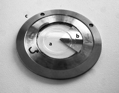
Fig. 3.
4Pi sample holder. In order to be accessible for both objective lenses, the sample is sealed in medium between two coverslips (a, Ø 18 mm and b, Ø 30 mm) that rest on a steel ring (c). A one-quarter mirror coating on the inward face of b facilitates aberration correction by reflecting the individual excitation beams back towards the detector.
6.
Coverslips No. 1.5, manually selected d = 170 μm ± 10 μm, small Ø (e.g., Ø = 12 mm) (Menzel Gläser).
7.
Coverslips No. 1.5, manually selected d = 170 μm ± 10 μm, large Ø (e.g., Ø = 30 mm) (Menzel Gläser), with custom Al mirror coating (see Fig. 3).
8.
2,2-Thiodiethanol (TDE), highest purity (Sigma-Aldrich).
9.
Phosphate-buffered saline (PBS), pH 7.4.
10.
Refractometer.
11.
FluoSpheres fluorescent microspheres, Red (580/605, for 1PE) or Yellow-green (505/515, for 2PE), Ø = 100 nm (Invitrogen).
12.
Absolute ethanol.
13.
Nail polish.
3 Methods
The coherent use of opposing lenses involves a special sample preparation protocol and introduces additional parameters that have to be controlled during the imaging process. This section discusses the design of a beam scanning 4Pi microscope and describes alignment procedures in chronological order of the workflow: One-time procedures that are used to set up the microscope, and routine adjustments that typically have to be executed repeatedly between measurements. Finally, a simple deconvolution approach is introduced as a means to free the acquired images from ghosting.
3.1 The 4Pi Microscope Set-Up
As an interferometric device, a 4Pi microscope is susceptible to temperature changes. Ensure that the installation site of the microscope is stabilized at the specified operation temperature of the objective lenses (T = 23°C) to about ±1°C by proper air-conditioning. Due to the increased axial resolution, vibration isolation by an optical table with pneumatic damping is highly recommended.
To enable 4Pi imaging on a conventional (beam scanning) confocal microscope (18), the objective turret and the sample stage are replaced by a module that accommodates the objective lens pair, a suitable sample stage and the necessary optics. The standard layout of this “4Pi unit” is outlined in Fig. 2. It exhibits six additional degrees of freedom that require active fine control, typically in form of piezo actuators.
Translation of one objective lens (O2) in all three dimensions allows keeping both lenses pointing at the same spot in order to create a diffraction-limited common focus.
Variation of the optical path length difference (OPD) between the two interferometer arms by a moveable mirror (M3) changes the phase (ϕ4Pi) between the two incident wave fronts at the focus and is used to set up constructive interference at the focal center (φ4Pi = 0).
Finally, two more degrees of freedom are introduced by beam scanning, which addresses lateral image coordinates by the scan angle of the beam at the entrance pupil of the objective lens. The mirror symmetry of the 4Pi unit ensures that during image acquisition, the same scan angle is applied to both objective lenses and thereby both foci remain coincident and interfere. However, if the pivot points of the beams do not rest at corresponding positions within each pupil, the planes of constant phase (PCP) between the incident wave fronts are no longer parallel to the focal plane, and ϕ4Pi thereby becomes a function of the scan angle. Rotational freedom of M3 allows aligning both pivot points, which eliminates this undesired dependency.
3.1.1 Objective Lenses and Sample Optics
The crucial optical elements of a 4Pi microscope are the sample itself and the pair of objective lenses. The removal of ghost images requires sufficiently low amplitude of the side maxima of the PSF, which is governed primarily by the semi-aperture angle α of the objective lenses used. Large α that enable 4Pi type A imaging with single-photon excitation are provided by oil immersion lenses with a high numerical aperture (NA) that have become commercially available for the use in total internal reflection microscopy.
Since aberrations can quickly spoil the benefits of these lenses (see Note 1), care has to be taken to employ them under their design conditions which cover temperature (T ), slide thickness, (d) and the refractive index (RI) of the immersion oil (n), which is temperature dependent.
The RI of the immersion oil has to be matched by the RI of the mounting medium, since due to the 4Pi geometry at least one lens will be focusing deep into the sample at any time. Mounting in TDE (15) was originally developed for this reason and is described in Subheading 3.2.1.
Spherical aberrations that are already introduced by small deviations from these specifications can be assessed by evaluating the reflection from a mirror that is scanned through the focus, and compensated by the correction collars of the objective lenses, if present (see Subheading 3.4.1).
For the use as a 4Pi pair, two individual lenses have to be selected or factory-adjusted such that their axial chromatic shifts Δ 1,2 between the excitation line λ e and the mean of the detection band λ d are small (∼ < 100 nm) to maintain confocality for both wavelengths (see Note 2).
Furthermore, a residual magnification mismatch of the lens pair will limit the field of view (FOV) that can be attained by beam scanning without additional corrections. The tolerable lateral separation between both foci amounts to about half of their lateral full width at half maximum (FWHM, ∼100 nm). A magnification mismatch of 5 ‰ would introduce this separation over a FOV of 10 μm diameter.
3.2 Sample Preparation with TDE Mounting Medium
TDE (2,2-thiodiethanol) is an inexpensive, nontoxic glycol derivative that is used as a mounting medium (15, 19) for technical and biological samples (see Note 3). Pure TDE (see Note 4) exhibits a refractive index of n D23 = 1.521 (at 589 nm and 23°C), and can be precisely tuned to the RI of immersion oil (n = 1.518) by the addition of water (n = 1.333) (see Note 5) or buffer to maintain the optimal pH for the dye in use.
3.2.1 Preparing TDE Mounting Medium
To prepare TDE embedding medium that matches the refractive index of immersion oil:
1.
Mix 97 ml 2,2-thiodiethanol (TDE) with 3 ml PBS (see Note 6).
2.
Stir for at least 15 min.
3.
Adjust pH to 7.5 with HCl/NaOH (see Note 7).
4.
Check refractive index with refractometer and adjust refractive index to 1.518 by addition of 100% TDE or PBS, if necessary (see Note 5).
Direct application of TDE medium to an aqueous cell sample involves the risk of distorting the cellular structure by osmotic shock. Therefore, a dilution series is required to ensure a slow exchange:
3.2.2 Embedding the Sample in TDE Medium
1.
Prepare TDE dilution series with PBS: 10% (v/v) TDE, 25% (v/v) TDE, 50% (v/v) TDE, and 97% (v/v) TDE.
2.
Incubate labeled sample in 10% (v/v) TDE for 10 min.
3.
Incubate labeled sample in 25% (v/v) and 50% (v/v) TDE for 5 min each.
4.
 Introduction: Nanoimaging Techniques in Biology
 Two-Color STED Imaging of Synapses in Living Brain Slices
 Secondary Ion Mass Spectrometry Imaging of Biological Membranes at High Spatial Resolution
 Functional AFM Imaging of Cellular Membranes Using Functionalized Tips
 Correlative Optical and Scanning Probe Microscopies for Mapping Interactions at Membranes
 Nanoimaging Cells Using Soft X-Ray Tomography


Incubate labeled sample in TDE medium twice for 5 min each.
Related posts:
Introduction: Nanoimaging Techniques in Biology
Two-Color STED Imaging of Synapses in Living Brain Slices
Secondary Ion Mass Spectrometry Imaging of Biological Membranes at High Spatial Resolution
Functional AFM Imaging of Cellular Membranes Using Functionalized Tips
Correlative Optical and Scanning Probe Microscopies for Mapping Interactions at Membranes
Nanoimaging Cells Using Soft X-Ray Tomography
Stay updated, free articles. Join our Telegram channel
Full access? Get Clinical Tree
