Introduction
A large variety of medical apparatus is used in the treatment of spinal disease and injuries. New devices are constantly being introduced. Most have been used for years, and many of the newest devices are variations on a previous theme. Knowing the specific name of a device is not important; in fact, it is sometimes impossible, because a slight modification of a device design usually leads to a new name. However, it is important to recognize the presence or absence of a device (if the patient’s history suggests one is present), to understand its function, and to identify any complications associated with its use.
Overlying Materials
Normal everyday items carried or worn by patients – eyeglasses, earrings, hearing aids, long hair, gown snaps, and jewelry – may be mistaken for a medical device or foreign body; or, they may interfere with radiographic evaluation of the underlying soft tissue and bony structures. Earrings often show up on head and neck radiographs. They usually cause no confusion, but at times they can resemble electronic apparatus or even cervical spine fixation apparatus (Figure 6.1). The combination of frontal and lateral views help to correctly identify earrings from medical apparatus. Even if there are frontal and lateral views, it may be difficult to distinguish unusual earrings from hearing aids.
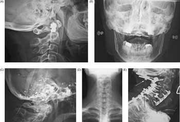
Figure 6.1 Earrings. (A) These resemble cervical spine apparatus on the lateral view. (B) AP view shows the earrings more clearly. (C) Residual Pantopaque in the base of the cranium from a myelogram performed with Pantopaque many years prior. (D) Long hair overlying the cervical spine and neck may simulate foreign material or a soft-tissue abnormality. (E) 70-year-old woman with severe rheumatoid arthritis and chronic atlantoaxial subluxation. There is occiput to T1 posterior spinal fusion and anterior spinal fusion from C3 to C7. One of the occipital screws is “proud” (white arrow). Two gown snaps (black arrows) simulate dislodged apparatus. A tracheostomy tube is also present.
Dental and facial apparatus is often present on cervical spine radiographs and should be evaluated as best as possible even though its evaluation was not the original intent of the imaging study. It is not all that uncommon for important maxillary, mandibular, or dental disease to be incidentally noted on routine imaging of the head, neck, or cervical spine.
Neck Apparatus
Gastric and Tracheal Tubes
Many medical devices travel through the neck en route to thoracic and abdominal structures (Hunter & Taljanovic, 2001; Price, 1991; Stoelting, 1986). Endotracheal tubes, tracheostomy tubes, orogastric tubes, nasogastric tubes, oral airways, and feeding tubes are common findings on cervical spine and chest radiographs (Figures 6.2 and 6.3). Because these tubes start from similar locations and go through neighboring structures, it is often difficult to differentiate between tracheal and gastric tubes, especially on bedside chest radiographs. Both may be placed through the nose, and they overlap in size and appearance. However, small tubes – especially those less than 5 mm in diameter – are usually feeding tubes. Endotracheal and nasogastric tubes are composed of radiolucent materials, but the manufacturers usually add a barium stripe or other high-density stripe to make the tube easily visible on radiographs.

Figure 6.2 (A) Dorsal column stimulator (DCS), nasogastric tube, and endotracheal tube. Lateral radiograph of the neck shows a recently placed dorsal column stimulator, a nasogastric tube (black *), and an endotracheal tube (white *). (B) Nasotracheal and orgogastric tubes. The nasotracheal tube is larger and anterior. The orogastric tube is smaller and posterior (arrow).

Figure 6.3 Esophageal temperature probe. There is also a pulse oximater probe on one of the earlobes, an endotracheal tube, and an anterior cervical fusion plate.
Even so, it may still be hard to differentiate an endotracheal tube from a nasogastric tube. Endotracheal tubes can be more easily recognized on lateral views because they lie anterior to gastric tubes and within the airway. They can often be identified if they are seen to pass between the vocal cords. Endotracheal tubes, orogastric tubes, and oral airways are placed through the mouth. They are much less common than nasogastric tubes, which are placed through the nose. Oral airways are made of rubber or plastic, but they are usually reasonably opaque, and they can be recognized at times by their location and their H or oval shape in cross-section. They are placed only for a short-term or emergency intubation.
Most of the time, endotracheal intubation is life-saving. Unfortunately, it can also be life-threatening if the tube is not in the proper position. The location of the endotracheal tube tip should always be ascertained. When the neck of an adult is in a neutral position, the tip of the tube should be approximately 5 cm above the tracheal carina at about the level of the aortic knob. In children, depending on their size, the tube tip should be 2–5 cm above the tracheal carina. In general, the tracheal carina is just distal to the level of the aortic arch. If the tip of the endotracheal tube is just above the aortic knob, it is in good position, midway between the vocal cords and the carina. This position allows safe excursion of 2 cm upward or downward when the patient flexes or extends the neck. Tubes tend to descend when the neck is flexed and ascend when it is extended.
If the endotracheal tube has a cuff, the balloon should not be inflated to more than one and a half times the diameter of the trachea. Prolonged overextension of the endotracheal cuff can lead to ischemic necrosis of the tracheal cartilage and tracheomalacia.
Tracheostomy tubes are composed of dense plastic or metal and are readily visible on most images (Figure 6.4). In an ideal situation, they are placed by an experienced surgeon for a patient who requires prolonged respiratory therapy or to provide an airway for a patient who has suffered grievous injury to the upper airway, neck, or face. Tracheostomy tubes are usually inserted between the second and third tracheal rings. They can be placed emergently, but in some emergency situations, a cricothyroid tube is used instead. Cricothyroid tubes are easier and quicker to insert than tracheostomy tubes, but they carry a higher risk of vocal cord damage. They may be difficult to distinguish from a tracheostomy tube unless one is provided with an adequate history of a cricothyroid tube insertion.

Figure 6.4 Tracheostomy tubes. (A,B) AP (A) and lateral (B) views show incorrect placement of a tracheostomy tube. The tip of the tube is to the left of the trachea on the AP chest view and anterior to the airway (arrow) on the lateral neck view.
Vagus Nerve Stimulator
Vagus nerve stimulation is an experimental technique for controlling seizures in patients for whom drugs and surgery have been ineffective (Morris & Mueller, 1999; Rosenbaum & Heninger, 2000; Terra et al., 2014). A vagus nerve stimulator consists of a small electrode, which is implanted around the left vagus nerve in the left side of the neck (Figure 6.5). The electrode is connected to a programmable generator, which is placed under the skin in the upper left side of the chest. Left vagus nerve stimulation is thought to have little effect on the heart, whereas right vagus nerve stimulation produces more cardiac effect.

Figure 6.5 (A,B) A left vagus nerve stimulator was placed to treat intractable epilepsy. (C) The battery pack (generator) for the stimulator overlies the left chest with stimulator lead (arrows) going into the left side of the neck.
Experimental work has shown that stimulating the vagus nerve innervates a number of organs, including the heart, lungs, larynx, vocal cord, stomach, tongue, and ears, and it sends sensory signals into the brain stem. For unknown reasons, such stimulation may control seizures, and it has also been shown experimentally to be successful in treating depression (Ogbonnaya & Kaliaperumal, 2013). It may also have a therapeutic effect in treating chronic syncope (Figure 6.6).

Figure 6.6 Bilateral vagus nerve stimulators. 62-year-old man with anterior cervical fusion plate and screws C5–7 for treatment of prior cervical spine trauma. Bilateral vagus nerve stimulators were placed to treat chronic syncope.
Lumboperitoneal Shunt
Communicating hydrocephalus (non-obstructive hydrocephalus) is usually treated with a ventriculoperitoneal shunt or, occasionally, a ventriculoatrial shunt. Another less frequently used option is the lumboperitoneal shunt (Bloch & McDermot, 2012; Burgett et al., 1997; Li, 2001) (Figure 6.7). Because it does not require a transcranial approach, a lumboperitoneal shunt is potentially safer for the patient. A programmable shunt that will allow valve pressure settings to be periodically adjusted can be used. The shunt may be laparoscopically placed at the midlumbar level with drainage of the spinal subarachnoid space into the peritoneal cavity. Lumboperitoneal shunts are sometimes used to treat pseudotumor cerebri and other nonspecific conditions. They tend to fail more commonly than ventriculoperitoneal shunts, and they have all the usual potential complications associated with shunts, such as infection, migration, tubing disconnection, hemorrhage, and chronic pain.

Figure 6.7 Lumboperitoneal shunt. 45-year-old woman with two lumboperitoneal shunts to treat pseudotumor cerebri. The inferior shunt tip is at the L4–5 level (lower arrowheads). The superior shunt (upper arrowheads) goes into the thoracic region with its tip not pictured.
Temperature and Oxygen-sensing Probes
Accurate measurement of body temperature and oxygenation is an important part of patient care, especially for patients undergoing extensive surgery; those suffering from hypothermia, hyperthermia, or heat stroke; and those in profound shock from trauma or sepsis (Mekjavic & Rempel, 1990; Robinson et al., 1998; Vicenzi et al., 2000). There is a variety of temperature-monitoring devices including axillary temperature patches, esophageal temperature probes, temperature probes incorporated in urinary catheters, electronic thermistors inserted into the pulmonary artery, and rectal temperature probes.
The choice of the probe type depends on the patient’s condition and the experience of the patient’s physicians. Esophageal and nasopharyngeal temperature probes may be seen in operative or immediate postoperative patients (Figure 6.3). These probes are commonly placed through the mouth and may be evident on neck and cervical spine images. The tip of the probe sometimes lies in the oropharynx or the proximal esophagus. The probes come in various designs, and some can monitor electrocardiographic tracings, heart rate, corebody temperature, aortic flow waveforms, and oximetry. The proper placement of an esophageal or nasopharyngeal probe is subject to much discussion. Some advocate that the probes be placed in the retrocardiac portion of the esophagus where they are less influenced by the exchange of gases in the mouth and upper airway. Others believe it is easier to place the probes in the neck because retrocardiac placement is more difficult to perform accurately.
Cervical Spine Instrumentation
Anterior and Posterior Cervical Plates
Approximately 1.2 million spine surgeries are performed annually in the United States. General indications for spinal surgery are degenerative disease, trauma, spinal tumors, and spinal infection.
Surgical fusion is a common treatment for cervical spine disk disease not amenable to more conservative therapy. Modern techniques with fixation stabilization hardware and disk replacement are designed to reduce the development of adjacent segment degeneration which often occurs after spinal fusion (North, 2012; Pescavage-Thomas & Ha, 2014). Goals are to restore and maintain disk space height, to decompress the spinal canal and neural foramina, to maintain normal lordosis and increase the stability of the involved segment. New instrumentation has also been designed to reduce bony non-union and hardware slippage or breakage.
Anterior and posterior cervical fusion plates are used in cervical spine surgery for trauma, tumor, degenerative disease, and inflammatory conditions (Bohler & Gaudernak, 1980; Churney et al., 1991; Cooper et al., 1988; Crockard & Ransford, 1990; de Oliveira, 1987; Gore et al., 1986; Larson et al., 1975; Lesoin et al., 1985; Stauffer, 1988; Tippets & Apfelbaum, 1988). In most instances, anterior cervical fusion plates are used in conjunction with supporting bone grafts (plugs) and dowels as interbody disk spacers, so-called anterior cervical (spine) diskectomy and fusion (ACDF) (Figures 6.8 and 6.9).

Figure 6.8 Anterior cervical fusion plate. 53-year-old man with disk herniation. Anterior cervical fusion plate spans C3–6. Interbody disk bone plugs (spacers) are present at C3–4, C4–5, and C5–6. (A) AP view. (B) Lateral view.

Figure 6.9 Anterior cervical disk fusion (ACDF) at C5–6. The disk cage at C5–6 is probably composed of polyethylene ketone (PEEK).
The best-known anterior cervical fusion plates are the Caspar plate (Tippets & Apfelbaum, 1988) and the Orion plate. The term Caspar plate is sometimes used generically to describe any type of anterior cervical fusion plate.
There are also zero-profile ACDF systems using a low-profile spacer anchored by fixation screws into vertebral bodies above and below the diskectomy level (Figures 6.10 and 6.11). They may produce a lower amount of postoperative dysphagia compared to the more traditional ACDF plates. In general, zero-profile ACDF systems are indicated for single-level use only in the anterior cervical spine from C2 to T1. They may have tantalum radiopaque markers to verify placement (Figure 6.12).

Figure 6.10 Zero-profile anterior cervical disk fusion (ACDF). 54-year-old woman with C6–7 zero-profile ACDF discovered incidentally on a thoracic spine series after a fall. A polyethylene ketone (PEEK) disk cage is at C6–7 held in place by anterior interbody screws.

Figure 6.11 (A) Zero-P (DePuy Synthes) low-profile anterior interbody fusion device. © DePuy Synthes 2016. All rights reserved. ZERO-P® is a trademark of DePuy Synthes. (B,C) Zero-P (DePuy Synthes) low-profile anterior interbody fusion device.

Figure 6.12 (A) Prevail Cervical Interbody Device (Medtronic). Reprinted with the permission of Medtronic, Inc. © 2016. (B,C) Prevail Cervical Interbody Device (Medtronic) at C7–T1. There are also posterior screws and connecting rods at C6–T1 on the right and at C6, C7, and T1 on the left. The right and left C6 and left C7 screws are in the lateral masses. The T1 screws are in the pedicles.
Anterior cervical plates are designed to span two or three vertebral bodies. They are anchored to the underlying vertebral bodies with screws, which should enter the anterior cortex of each vertebral body and be seated in the posterior cortex without impinging on the cord. Ideally, the screws should not enter an adjacent end plate and should be at least 2 mm from the superior and inferior end plates.
Posterior cervical plates are less common than anterior cervical fusion plates, but are used commonly in trauma patients (Figure 6.13). If there is posterior compression of the thecal sac and resection of posterior elements is required, posterior stabilization with a plate and screw provides an excellent means of achieving spinal stability.

Figure 6.13 (A) Occipital strut with posterior cervical plates. (B) Posterior cervical spine clamp. Patient with rheumatoid arthritis and atlantoaxial (C1–2) subluxation and generalized cervical spine laxity. (C) Occipital strut and posterior cervical spine fixation for C1–2 subluxation. Middle-aged woman with rheumatoid arthritis and unstable atlantoaxial (C1–2) subluxation. Note the wide separation between the odontoid and the anterior ring of C1. The cervical spine was stabilized with an occipital strut held in place by occipital screws and rods extending from the occiput to C2. Lateral mass screws are present connecting to the rods at C2, and there is also posterior spinal wiring.
Posterior plates limit both extension and flexion, and they are usually attached to the underlying vertebrae by screw fixation to the articular masses. Currently, two major types of plates or rod systems are used posteriorly in the cervical spine: those that are attached through screws placed in the pedicles of the cervical vertebrae and those that are attached through screws placed in the lateral mass of each cervical vertebra.
In the C2 vertebra the pedicles are used for screw placement; in the C3 to C6 vertebrae, lateral mass screws are preferred. The smaller pedicle diameter at these levels is associated with an increased potential risk of pedicle perforation and potential for vertebral artery injury. On imaging lateral mass screws have an upward orientation on lateral radiographs and outward orientation on AP images without extension into the pedicle. Pedicle screws extend more anterior to the lateral mass and into the pedicle with a more horizontal orientation on lateral imaging and inward orientation on AP images (Figure 6.12).
The C7 and T1 vertebrae are most suited for placement of pedicle screws (Figures 6.14–6.16). Sometimes more exotic posterior cervical spine fixation may be seen, such as a posterior fixation clamp (Figure 6.13B).


Figure 6.14 (A,B) Odontoid screw (nail). There is also an anterior cervical fusion plate and screws from C3 to C6. (C,D) Odontoid screw (nail) fracture fixation with posterior cervical fixation plates and screws extension (C) and flexion (D) views. (E–H) Odontoid fracture fixation. 47-year-old woman with type III dens fracture treated by occiput–C2 fusion.

Figure 6.15 (A,B) Young woman with traumatic locked facets at C6–7 and C7 body fracture. A posterior cervical fusion with lateral mass screws (cervical spine) and pedicle screws (thoracic spine) and rods extends from C4 to T2. There is an anterior cervical fusion plate and screws at C6–7 with a intervertebral disk cage at C6–7 and a crosslink at C6. (C,D) Cervical spine anterior and posterior fusion with intervertebral bone struts (plugs). There is an anterior cervical fusion plate that extends from C3 to C7 and posterior lateral mass screws and rods on each side from C3 to C7. Intervertebral bone struts (plugs) are present at the disk spaces from C3 to C6.

Figure 6.16 Posterior cervical spine fusion from occiput with halo brace. 53-year-old man with congenital cervical spine fusion and traumatic fracture through fusion mass at C3–7. The spine is stabilized by surgical fusion hardware from the occiput to T2 plus a halo brace.
Anterior and posterior cervical fusion plates often consist of Vitallium, an alloy of cobalt, chromium, and molybdenum. Vitallium is less corrosive than stainless steel. It is more compatible with MR imaging than stainless steel, although it will still produce a marked magnetic susceptibility artifact. Cervical fusion plates are not a contraindication to MR imaging, but they can produce troublesome artifacts limiting the usefulness of an examination (Stradiotti et al., 2009).
Posterior Cervical Spine Wiring
Use of posterior cervical spine wiring is now less common than fixation with anterior cervical fusion plates (Johnson et al., 1981). Posterior cervical spine wiring is very good for limiting flexion of the spine, and it is less complicated than anterior cervical fusion and plating (Figure 6.17–6.19). It is poor for preventing spinal rotation and for treating patients who have anterior compression on the thecal sac. Twenty-gauge stainless steel wire is used most frequently for posterior cervical spine wiring. There are many variations in the wiring technique. These include wires under the lamina, over the lamina, and through holes drilled in the facets or spinous processes. In addition, intralaminar or spinous bone grafts are sometimes placed to supplement the wires.

Figure 6.17 Posterior cervical spine wiring. (A) Posterior cervical wires extend from C4 to C7 after laminectomy. The lateral view (B) was obtained obtained after cervical myelography.

Figure 6.18 Odontoid fracture fixation. Postoperative lateral radiograph of the cervical spine. There is fixation of an odontoid base fracture by an odontoid screw and a sublaminar wire between C1 and C2. There are also skin staples and a surgical drain in the posterior aspect of the neck.

Figure 6.19 44-year-old man with C7 vertebral fracture. Posterior figure-of-8 wire fixation extends from C4 to C7. (A) AP view. (B) Lateral view. (C) Sagittal CT reformatted image.
Odontoid Fracture Fixation Devices; Atlantoaxial Subluxation; Traumatic C1–2 Fracture Dislocation
Type 1 odontoid fractures occur at the tip of the odontoid and are stable and heal with conservative treatment. Type 3 odontoid fractures involve the vertebral body of C2 below the level of the odontoid (Figure 6.14). They are usually stable and heal adequately. Type 2 odontoid fractures run transversely at the base of the odontoid. They are considered to be unstable and sometimes do not heal adequately with simple external fixation (a halo vest). For these types of fractures, internal fixation may be performed, especially when reduction of the odontoid is needed.
Reduction is generally required if the odontoid fracture fragment is displaced more than 4 mm anteriorly on the body of C2. Posterior cervical fixation wires are commonly used for treating type 2 odontoid fractures (Figure 6.18). They usually achieve satisfactory odontoid fusion, but they may limit neck rotation. Because of this, odontoid fracture fixation may use an odontoid compression screw or nail (Esses & Bednar, 1991) running caudad to cephalad through the body of C2, the odontoid fracture line, and into the body of the odontoid (Figure 6.14). On rare occasions, two odontoid fixation screws may be used (Figure 6.20).

Figure 6.20 Two odontoid screws. 86-year-old woman with C1 posterior ring and type II dens fractures two months earlier treated with two odontoid (dens) screws.
Chronic atlantoaxial subluxation, most commonly seen in patients with advanced rheumatoid arthritis, ankylosing spondylitis, or Down’s syndrome, is difficult to treat. There is often poor bone stock, and many patients are not good operative risks due to their chronic disease and the possibility of grievous neurologic injury during intubation and general anesthesia. Sometimes, the subluxation is treated with close observation and conservative therapy with neck braces as well as aggressive treatment of the underlying disease. At other times surgical intervention is applied, particularly if there are neurological symptoms. This usually involves posterior stabilization of the upper cervical spine with rods and screws that extend from the upper cervical spine to the occiput (Figures 6.13). Or, there is C1–2 posterior transarticular fixation with screws and connecting rods frequently with C1 lateral mass and C2 pedicle screws sometimes with associated posterior bone grafting (Xie et al., 2009).
Traumatic bilateral atlantoaxial dislocations are very rare and less common than hangman fractures at C2–3. There may be a traumatic C2 spondylolisthesis along with a C1–2 rotary subluxation. Patients are initially treated in a halo crown and vest and then followed by posterior surgical C1, C2, and C3 reduction and fixation (Chaudhary et al., 2015).
Intervertebral Disk Cages; Interbody Fusion Cages; Spine Cages; Titanium Interbody Spacers
The term spine cage or disk cage (spacer) applies to a variety of spinal devices found most commonly in the lumbar spine but also found in the cervical and thoracic spine. The original cages were typically hollow, cylindrical implants placed into a disk space to restore disk height and allow bone growth. The most frequent cages were porous and composed of stainless steel or titanium with autologous bone chips placed inside the cage (Figure 6.21). It should be noted that spine cages (disk cages) can be stand-alone or combined with spinal fusion plates and rods. It should also be noted that there is considerable overlap in terms and inconsistency in their usage.

Figure 6.21 Lumbar spine disk spacers at L4–5 and L5–S1. 59-year-old woman with past history of spinal surgery.
In the cervical spine, a bone plug from autograft or allograft material, such as a small cylindrical piece of rib or fibula, may be placed in a disk space and combined with an anterior cervical fusion plate (Figures 6.8 and 6.15).
Vertebral disk cages are nowadays also composed of polyether ether ketone (PEEK) mixed with autologous bone graft (Petscavage-Thomas & Ha, 2014) (Figures 6.9, 6.22, and 6.23) or poly(l-lactide-co-d,l-lactide) (PLDLLA), a radiolucent resorbable biopolymer. PEEK has an elasticity closely resembling that of cortical bone, possibly having more load-sharing and better stress distribution with more strength than many metals. It does not cause significant artifact on MRI or CT.


Figure 6.23 (A,B) Anterior cervical discectomy and fusion (ACDF) at C5–7 with polyethylene ketone (PEEK) disk cages at C5–6 and C6–7. (C) Medtronic titanium-coated PEEK disk cages.
Spine cages are most commonly used to maintain foraminal height and spinal decompression, whether stand-alone or combined with other fixation apparatus (Figures 6.23–6.26). The zero-profile systems described above are a form of disk cage with fixation screws for insertion into vertebral bodies above and below the cage (Figure 6.11).

Figure 6.24 (A) Cervical spine fusion cage and anterior cervical fusion plate. (B) Cervical spine intervertebral disk fusion cage.

Figure 6.25 (A,B) ProDisc-C Total Disc Replacement. © DePuy Synthes 2016. All rights reserved. ProDisc® C is a trademark of DePuy Synthes. (C,D) 43-year-old woman with localized disk disease at C5–6. (E) Prestige Cervical Disc. This is a metal-on-metal artificial disk that is anchored to the vertebral bodies by anterior locking screws.

Figure 6.26 (A,B) Lumbar spine Steffee pedicle plates and screws and Brantigan disk cage (arrow). Note the associated solid posterolateral bony fusion masses. (C) Brantigan disk cage. In the lower right-hand corner of the cage there is a small metallic rod for radiographic identification. The cage is composed of high-density carbon fiber with grooves for bone incorporation into the vertebrae. (D) Lateral view in another patient shows two side-by-side Brantigan cages (arrows) at L2–3.
Vertebral disk cages like all other spinal fixation apparatus have a potential for complications including non-union, cage migration, infection, foraminal compression, nerve root compression, cord compression, and not uncommonly adjacent segment degeneration from loss of cervical or lumbar lordosis and shift of spine movement to levels where there is no spine fusion (Figure 6.27). The disk cages may also cause considerable artifacts on MRI and CT imaging (Figures 6.28 and 6.29).

Figure 6.27 (A,B) Subsidence of polyethylene ketone (PEEK) cage device 3 months after surgery. (A) An anterior cervical fixation plate and screws has been placed with PEEK disk cages at C5–6 and C6–7. (B) Three months after surgery the disk cage at C6–7 has subsided and slipped anteriorly. (C,D) Anterior cervical disk fusion with junctional disease above the level of fusion. (C) This radiograph was obtained on February 11, 2013. (D) This radiograph was obtained on July 22, 2015. It shows degenerative changes developing at the C4–5 disk space above the anterior fusion going from C5 to C7.

Figure 6.28 Susceptibility artifact from cervical spine disk prosthesis. 43-year-old man with metallic cervical disk prosthesis at C5–6. Metallic susceptibility artifact completely obliterates imaging of the spine and spinal cord at this level.

Malignant disease, severe infectious disease, or major trauma to the spine can destroy one or more vertebral bodies. This destruction may be treated with vertebral body resection (corpectomy) and bone grafting combined with placement of a vertebral body “cage” (Figure 6.30). The cage may be free-standing or associated with a lateral, anterior, or posterior fixator to give the reconstructed area more strength (Figure 6.31).

Figure 6.30 Harms vertebral cage. There is a vertebral cage and side plate and screws in the lower thoracic spine for treatment of a spinal tumor. (A) AP view. (B) Lateral view.

Figure 6.31 Cervical spine “corpectomy” and fusion. Elderly woman with diskitis at C4–5 and adjacent bony destruction by osteomyelitis at C4 and C5. Initial cervical fusion failed. A corpectomy cage was placed at C4–5 with posterior spinal fusion from the occiput to T2. A crosslink is at C6.
These cages are generically called titanium interbody spacers. They are usually manufactured from titanium, which has good strength and good biocompatibility and also produces fewer artifacts on MR images compared with other metals such as stainless steel. These types of vertebral cages have a hollow, threaded, cylindrical structure with teeth on both sides for fixation to vertebral end plates superiorly and inferiorly. The hollow center is usually filled with autograft or allograft bone material to strengthen the fixation and provide later fusion. Many designs exist for the interbody fusion devices, and the designs are evolving. For example, there are newer expandable corpectomy devices for treatment of severe compression fractures or vertebrae collapse due to tumor. The expansion cage along with posterior stabilization screws and rods stabilize the spine to protect the spinal cord. They also restore a degree of vertebral height loss (Figures 6.32 and 6.33).

Figure 6.32 Vertebral compression fracture treated by expandable corpectomy device. (A) Compression fracture at L1. (B) Expandable corpectomy device has been placed at L1. There are also bilateral pedicle screws and connecting rods above and below the level of the fracture.

Figure 6.33 75-year-old woman with expandable corpectomy cage used to treat a comminuted T11 compression fracture (A,B). A follow-up study 3 months after cage placement (C) shows cage shift probably from increased fracture compression. The cage remained stable at that point.
Some of the more popular interbody fusion devices (spacers) used in the thoracic or lumbar spine are the Bagby and Kuslich cage, the Ray threaded fusion Cage, the Harms cage, and the Brantigan cage (Figures 6.24, 6.26, and 6.30). The Brantigan cage is designed to be placed through a posterior approach or posterior lumbar interbody fusion. Brantigan cages are composed of high-density carbon fiber, and two cages are placed side by side in a disk space. They are contiguous with bone graft material that is interposed between the vertebral end plates and the cages. These interbody cages are purposely designed to be radiolucent so that the interface between the bone graft and the vertebral end plate is well visualized and not hidden by the supporting cage. The cages areidentified on radiographs by a small metallic marker within each cage.
Cervical Collars and Halo Vests
There are many kinds of cervical spine immobilization devices, including cranial (head) tongs (Figure 6.34), cervical collars, neck braces, and halo vests. Cervical collars are ubiquitous and are commonly placed on trauma patients in the emergency department. The most frequent cervical collar design is the Philadelphia collar, which is molded from plastic and has chin and occipital supports. Although it is effective in stabilizing the neck to prevent harmful motion, it is uncomfortable, and patients want to remove it as soon as possible.

Figure 6.34 Cranial (head) tongs. (A,B) Child with severe intracranial and cervical spine injuries with bilateral cranial stabilization tongs, an endotracheal tube, an oroogastric tube, and a feeding tube entering via the nose. (C,D) Cranial (head) tongs are used to stabilize the head and neck in a patient with a cervical spine fracture. One or more screws penetrate the outer table of the skull on each side. They are connected to each other by horizontal or vertical bars on each side that are attached to an external traction device.
A more comfortable collar for patients is a soft foam collar covered by cotton. Although this collar is ineffective in controlling neck motion, it is useful as a reminder to the patient that neck motion must be avoided.
No neck collar provides adequate long-term neck stabilization for unstable cervical spine fractures. Unlike cervical collars, cervical braces are designed for the long-term treatment of cervical spine fractures. They consist of chin and occipital supports that are connected to a thoracic vest by metal rods. Cervical braces do provide good prevention against harmful flexion, but they are not as effective in preventing harmful extension.
The halo vest contains a metallic ring (the halo) that is attached to the outer table of the skull by screws (Bucholz & Cheung, 1989; Kostuik, 1981; Whitehill et al., 1986) (Figure 6.35). The halo is connected to a padded fiberglass or plastic thoracic cast by metal rods (the struts), which hold up the patient’s head. Although halo vests involve placement of screws into the skull and are a major undertaking for both the patient and the physician, they provide the best long-term fixation of the cervical spine. They are especially indicated for unstable fractures and dislocations and work best in the upper cervical spine.

Thoracic and Lumbar Spine Instrumentation
Spinal Implants
Thoracic and lumbar implant surgery is performed to correct severe congenital or developmental spinal deformities or defects. It is also used to stabilize the spine and repair damage to bone and ligaments resulting from trauma, typically motor vehicle accidents, gunshot wounds, and diving accidents. The main congenital disease indications are severe scoliosis, kyphosis in Scheuermann disease, spinal stenosis, and spinal dysraphism (Aebi et al., 1998; An & Cotler, 1999; Benzel, 2012; Cotrel et al., 1988; Drummond, 1988; Egnatchik, 1990; Ha & Petscavage-Thomas, 2014; Hitchon et al., 1995; Hu & Pashman, 1992; Luque, 1986; Selby, 1982; Slone et al., 1993a, 1993b, 1993c; Steffee et al.,1986).
Posterior Spinal Instrumentation
Posterior spinal instrumentation is preferred over anterior spinal instrumentation in the thoracic and lumbar regions, because it allows easier decompression and visualization of neural elements. The posterior surgical approach is much simpler and safer in general than an anterior approach going through the neck, chest, or abdomen. On the other hand, the anterior approach is generally preferred for spinal surgery in the cervical region for two reasons. First, posterior instrumentation in the cervical spine is usually limited, because the vertebrae in the cervical spine are smaller, as is the volume of the soft tissue. Second, the substantial implants used posteriorly in the thoracic and lumbar regions are too large to be used in the cervical spine. Mechanically, they would not safely fit in the cervical region, and the degree of support they provide for the thoracic and lumbar regions is not needed in the cervical spine.
Surgery to fuse the lumbar spine has been performed for more than 100 years. The techniques used for the earliest procedures involved only bone grafting in situ, and they are still applicable today. Currently, it is quite common to combine bone grafting with the use of spinal fixation apparatus to improve fusion rates. Successful bone grafts are necessary for the ultimate success of spinal surgery. If the bone grafting and eventual fusion are not successful, the spinal fixation apparatus will ultimately fail. Spinal implants are very useful, however, for they often permit less-extensive surgery, providing immediate spine stability, improved fusion rates, and rapid patient mobilization and rehabilitation.
One of the first practical applications of spinal fixation apparatus was the use by Luque of sublaminar wires attached to anchor rods for thoracic and lumbar spine posterior stabilization (Figure 6.36). Although this technique provided very secure fixation, it had a relatively high risk of associated neurologic complications. In Luque’s original technique, the wires were “blindly” passed under the lamina at surgery with no direct visualization of the spinal dura neurologic elements. The original technique has for the most part been replaced with use of segmental wires passed through the base of the spinous processes. The new technique is easier for the surgeon, and it avoids injury to the spinal cord and its nerve roots.

Figure 6.36 Bilateral Luque rods for treatment of scoliosis. The rods are fractured at the T12 level.
In a further modification of the original sublaminar wire technique, rectangular fixation devices (Luque and Hartshill rectangles) (Figure 6.37) or metallic buttons (Figure 6.38) are used with sublaminar wires designed to hold the metallic rectangles or buttons to adjacent vertebrae. Harrington rods (flanged ends) and Knodt rods (threaded rods) have hooks along the rods (Figure 6.39). They are designed to either distract the spine or compress it, depending on the direction in which the hooks are placed. The distraction or compression is used to treat a variety of congenital and developmental deformities,such as marked adolescent scoliosis. Sometimes, the deformity is stabilized so that it will not worsen as the patient grows older. Sometimes, the deformity can actually be partially corrected. This type of apparatus may also be used to secure the spine after the collapse of a vertebra from trauma, infection, or tumor.

Figure 6.37 Hartshill rectangle used to treat degenerative disease in the lower lumbar spine. There is surrounding bone fusion. The wires through the sacral lamina are broken, which is not a problem with the solid bony fusion.

Figure 6.38 Wisconsin posterior spinal wiring. The wires go under the lamina and are connected to buttons that sit external to posterior elements of the spine. (A) AP view. (B) Lateral view.

Figure 6.39 Harrington rods. (A) The hooks on these rods are designed for distraction. (B) Harrington rods are at the thoracolumbar junction stabilizing a vertebral body fracture. The hooks (thick arrows) anchor the rods in the lamina. Segmental wires around the lamina (thin arrow) supplement the fixation. (A,B) from Hunter & Taljanovic, 1994. (C,D) Harrington rods (flanged ends) and Knodt rods (threaded rods) have hooks along the rods, designed to either distract the spine or compress it, depending on the direction in which the hooks are placed.
Thoracolumbar stabilization rods have a long record of success and are among the most commonly used spinal stabilization apparatus. They do have the disadvantage of their sublaminar hooks, which can compress the thecal sac or directly harm the neural roots or even the spinal cord. In the lumbar spine, they also tend to cause a loss of the normal lumbar lordosis (the so-called flat-back syndrome), which may produce disabling chronic pain over time. Pedicle fixation systems were designed to overcome these problems. In these fixation systems, screws are placed through the pedicles into the vertebral bodies. The screws are connected together on each side, with rods or a plate placed over the pedicle screws on each side. There are many variations on this common design, with several systems now available, including the Steffee, Edwards, Roy Camille, and Cotrell–Dubousett devices (Figures 6.26, 6.40–6.43).

Figure 6.40 Extensive lumbar spine fusion with pedicle screws and rods. A laminectomy has been performed from T12–L5. Pedicle screws and rods are at L3–S1 from the initial lower lumbar spine fusion. Later surgery added pedicle screws and rods at T12–L3, and L3–5 with a crosslink at L2.

Figure 6.41 Steffee pedicle plates and screws. A laminectomy has been performed from L3 to S1 with bilateral Steffee pedicle plates and screws at L3 to S1 with solid posterolateral bony fusion masses. Brantigan disk cages are at L5–S1. (A) AP view. (B) Lateral view. Arrow points to Brantigan disk cages. (C) Oblique view.

Figure 6.42 Pedicle fixation screws and rods. 20-year-old woman with L1 vertebral body compression fracture treated with T12–L2 posterior spinal fusion using pedicle screws at T12 and L2 with connecting rods on each side.
The Steffee design is very common. It uses flat plates to connect the screws, whereas the Cotrell devices use rods to connect to the screws. The TiMx Comprehensive Low Back System is a titanium system composed of pedicle screws, spine plates, washers, rods, slotted connectors, and a cross connector. Most of these systems are combined with posterolateral “bony fusion masses” (osseous grafts) composed of bone pieces or bone shavings taken from the iliac crest tuberosity on one or both sides. The bony fusion masses are packed around the fixation devices, and in 4–5 months they evolve to become solid masses of mature bone. The fusion of bone provides the ultimate stability for the spine. If fusion is not successful, the fixation apparatus often eventually fails, with breakage or loosening of components.

Figure 6.43 Posterior spinal fusion apparatus. Shown are pedicle screws and rods on each side, two crosslinks (at L4 and S1), and intervertebral disk spacers at L4–5.
Anterior Spinal Instrumentation
The devices used for anterior spinal instrumentation are similar to those used for posterior spinal fixation and usually include plates and screws (Aebi et al., 1998; An & Cotler, 1999; Benzel, 2012; Hitchon et al., 1995; Hu & Oashman, 1992; Slone et al., 1993a, 1993b, 1993c). Anterior spinal fixation is common in the cervical spine, but, as discussed above, it is uncommon in the thoracic or lumbar spine. When it is used in the thoracic or lumbar regions, it is often designed to stabilize or correct a marked kyphosis or scoliosis. The anterior spinal apparatus is placed to impart a distracting force on the concave side of the scoliosis or a compressing force on the convex side of the scoliosis. It is also useful in anterior approaches to spinal tumors or metastatic disease.
Anterior lumbar interbody fusion (ALIF) has become more popular and is a somewhat limited procedure (Figure 6.44). It offers an easy approach to the anterior disk space without opening the spinal canal or neural foramina, such as the case with posterior lumbar interbody fusion (PLIF) or transforaminal lumbar interbody fusion (TLIF). ALIF allows the placement of a large interbody fusion device and easy and complete discectomy (Mobbs et al., 2013). ALIF is used for chronic back pain of discogenic origin over 1–3 levels.


Figure 6.44 (A,B) 47-year-old woman with anterior lumbar interbody fusion (ALIF) at L5–S1. (C,D) 60-year-old man with L5–S1 anterior diskectomy and interbody fusion (ALIF) with zero-profile fixation screws at L5–S1. There are polyethylene ketone (PEEK) interbody disk grafts at multiple levels from ALIF prior surgery at L2–3 to L4–5. (E–H) 48-year-old man with L5–S1 laminectomy and posterior spinal fusion (PSF) for radiculopathy and isthmic spondylolisthesis. There was hardware failure. A subsequent ALIF with a Sovereign cage device (Medtronic) was performed as well as revision of the PSF at L5–S1. (H) reprinted with permission of Medtronic, Inc. © 2016.
ALIF is often performed with zero-profile ACDF systems using a low -profile spacer anchored by fixation screws into vertebral bodies above and below the diskectomy level (Figure 6.45). The native disks are usually replaced with PEEK artificial disks. While ALIF is somewhat of a more limited surgery compared to several other approaches, it has the disadvantage of potential vascular or bowel injury resulting from the anterior approach to the spine. There has to be mobilization of the great blood vessels and peritoneal contents away from the spine exposing them to possible injury (Mobbs et al., 2013).


