Fig. 2.1
Bowel gas is demonstrated as a bright white line at the top of the screen with a gray shadow below obscuring the abdominal organs
If the pelvis is to be imaged, instruct the patient to drink water to facilitate bladder filling, as fluid conducts sound well allowing posterior structures to be adequately imaged. Consuming water immediately before the examination may also aid visualization of the pancreas or epigastric structures that lie posterior to the stomach. Hydronephrosis may also become more apparent when the patient is fully hydrated.
Selecting a Probe
Abdominal structures are best imaged with a low-frequency curvilinear probe. Occasionally a phased-array probe may be used. Some handheld units may only have a single low-frequency probe such as a phased array probe that is not interchangeable. Common probes are depicted in Fig. 2.2. Many machines have presets specific to certain abdominal structures and selecting these will help minimize the amount of setting adjustments needed for optimal imaging. Adjusting the frequency even lower than the standard setting may help visualize deeper structures, or may be necessary when imaging obese individuals.

Fig. 2.2
A phased-array (left) and curvilinear probe (right). Both are low-frequency, allowing for evaluation of deeper structures
Scanning
Kidneys
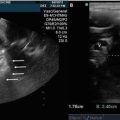
The kidneys are retroperitoneal structures that are well-situated for ultrasonography. The right kidney is normally easier to image than the left given that the liver provides a large acoustic window. A longitudinal view of the right kidney is obtained in the right upper quadrant. The probe may be placed either anteriorly or in the mid-axillary line, depending on the patient’s body habitus and liver size. After fanning through the entire structure, rotate the probe ninety degrees at the mid-kidney level to obtain a cross-sectional view. Length, width and anterior–posterior diameter should be recorded as shown in Fig. 2.3. Repeat this technique at the left flank to visualize the left kidney, using the spleen as an acoustic window. If difficulty is encountered, moving the probe more superiorly and posteriorly may allow better imaging of the left kidney. A seated position that brings the left kidney below the costal margin may also facilitate imaging.

Fig. 2.3
(a–b) A normal left kidney which lies adjacent to the spleen. Calipers mark the length in a mid-sagittal plane (a) as well as anterior–posterior diameter and width in the transverse plane (b). (Image courtesy of Victor Rao)
Bladder
The bladder lies anteriorly in the pelvis and is best visualized when filled with urine. Obtain a transverse view by placing the probe anteriorly just above the pubic symphysis in the midline, and angle inferiorly. Measure the depth (anterior–posterior diameter) as well as width (left to right diameter). Rotate along the midline axis ninety degrees to obtain a longitudinal image in the sagittal plane. In this view, record the length (craniocaudal diameter) Fig. 2.4. Some machines will automatically calculate bladder volume, but a formula, which approximates the volume based on assumptions of the normal bladder shape, may be used when all three dimensions are recorded:

 Performing this measurement immediately following voiding will give the post-void residual volume.
Fig. 2.4
A normal bladder as viewed in the mid-sagittal (a) and transverse (b) planes. (Image courtesy of Victor Rao)
Abdominal Aorta
A transverse view is first obtained by placing the probe in the sub-xiphoid position with the probe marker pointing towards the patient’s right side. The abdominal aorta is then traced from its proximal origin below the diaphragm to the bifurcation of the iliac arteries. This can then be repeated with the probe marker pointed towards the patient’s head for a long axis view of the aorta. In general the probe should be as perpendicular to the aorta as possible in order to avoid oblique cuts that can make the diameter appear larger than it actually is. At least one caliper measurement should be obtained at the widest portion of the aorta seen on the scan. Measurements should be obtained in a transverse view of the aorta as shown in Fig. 2.5. Calipers are placed at the widest segment of the aorta and measurements are taken from the outer wall to oute r wall, including thromb us if present.

Fig. 2.5
A transverse view of the distal abdominal aorta (AOD) with caliper measurements from outer wall to outer wall
Gall Bladder
A long axis view is obtained first by placing the probe with the marker pointing cephalad directly to the right of the midline in the sub-xiphoid position. The probe should be tilted slightly cephalad. A subcostal sweep can be performed by sliding the probe laterally until the gall bladder is visualized. The probe should then be adjusted until the gallbladder is visualized in its long axis. This maneuver is depicted in Fig. 2.6. The probe is then used to completely sweep from one side of the gall bladder to the other. The probe is then rotated 90° to a short axis view and a sweep is repeated from one side to the other. If there is difficulty finding the gallbladder, the patient can hold a deep breath to bring the liver edge below the rib cage. Additionally, if the patie nt rolls into the left lateral decubitus position the gall bladder may move closer to the abdominal wall and may be easier to visualize.

Fig. 2.6
Rotate the probe slightly from the sagittal plan to obtain a long axis view of the gallbladder
Focused Assessment Sonography for Trauma (FAST) Exam
The purpose of the FAST exam is to evaluate the pericardial and peritoneal cavity for free fluid. The standard FAST exam is com posed of views in four separate locations on the abdomen: the right upper quadrant (RUQ), left upper quadrant (LUQ), suprapubic (SP) or pelvic, and subxiphoid (SX). Starting with the RUQ coronal view, place the probe at the right flank at the level of the costophrenic angle with probe marker towards the patient’s head. As the liver usually spans most of the RUQ, the probe can be placed in the anterior, mid, or posterior axillary line. Using the liver as an acoustic window, visualize the liver, kidney, diaphragm, and vertebral bodies. In this view, the region of interest is a potential space between the liver and kidney, known as Morrison’s pouch . If intraperitoneal fluid is present, an anechoic space will appear to separate the liver and kidney. This is an abnormal finding and may indicate blood in the abdominal cavity in the setting of trauma. Fan the tail of the transducer up and down to sweep the transducer beam completely through Morrison’s Pouch. Slide the probe caudally or angle slightly inferiorly to ensure the inferior tip of the right lobe of the liver is visualized. This is important because free fluid is sometimes seen at the liver tip before tracking into Morrison’s Pouch .
Next, place the probe at the left costophrenic angle in the coronal plane with the probe marker towards the patient’s head. Using the spleen as an acoustic window, visualize the spleen, kidney, diaphragm, and vertebral bod ies. Here it is important to place the probe along the posterior axillary line. Rotating the probe slightly clockwise, so the indicator is towards the patient’s axilla, often helps to reduce rib shadows and improve visualization of the diaphragm. If free fluid is present it can generally be seen between the spleen and the diaphragm, while large amounts of free fluid often surround the spleen superiorly and laterally.
Next, place the probe just cephalad to the pubis symphysis with the probe marker towards the patient’s head. Using the full bladder as an acoustic window, look for free fluid cephalad and posterior to the bladder in males, and posterior to the uterus in the pouch of Douglas in females. Free fluid will tend to fill in spaces in the pelvis giving it an irregular shape with the appearance of sharp edges. When a large amount of fluid is present, the outline of the bowels is easily seen cephalad to bladder. Fan the tail of the transducer to ensure the entire region is seen. Next, obtain a transverse view by rotating the transducer 90° so the probe marker is pointed towa rds the patient’s right. Fan the tail of the probe up and down to visualize the entire region, looking for anechoic fluid posterior to the uterus in females or posterior and superior to the bladder in males.
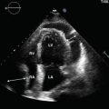
Finally, place the probe in epigastrum and slide cephalad into the subxiphoid position, angling towards the patient’s head with the probe marker towards the patient’s right. Use an overhand grip and position the probe at a relatively shallow angle. Using the left lobe of the liver as an acoustic window, obtain a 4-chamber view of the heart (described in the cardiac chapter) and visualize the interface between the right ventricle and the liver. The presence of pericardial effusion will appear as an anechoic region between the ventricular myocardium and the liver parenchyma. Fan the tail of the probe up and down to visualize the entire pericardium to include the posterior region.
The key components of the FAST exam are depicted in Fig. 2.7.

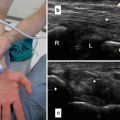
Fig. 2.7
(a) Probe points cephalad through liver (L), showing absence or presence of pericardial fluid (F). (b) Probe points toward midline in coronal plane, showing absence or presence of free fluid in the Morrison’s Pouch (MP) between liver (L) and kidney (K). (c) Probe points toward midline in coronal plane, showing absence or presence of fluid (F) surrounding the spleen (S). D = diaphragm. K = kidney. (d) Pelvic view in long axis showing normal filled bladder (B) approximated by air-filled bowel. On far right, free fluid (F) cephalad and posterior to bladder
Small Bowl Obstruction
In a normal abdomen small bowel is usually not visualized. However, in small bowel obstruction (SBO) dilated, fluid filled loops of bowel with abnormal peristalsis can be seen. In the supine patient scan in the more dependent region s along the right and left paracolic gutters, which are away from bowel gas.
Start with the probe in the right lower quadrant with the marker pointed towards the right shoulder and the beam angled across the abdomen in the coronal plane. Fan the tail anteriorly and posteriorly through the abdomen searching for dilated, fluid-filled loops of small bowel. Slide the probe cephalad along the right paracolic gutter while fanning. Repeat the process on the left side. Alternatively, a “lawn mower” technique can be utilized over the entire abdomen as depicted in Fig. 2.8.

Fig. 2.8
Diagram of “lawn mower” technique for scanning for dilated loops of bowel in small bowel obstruction
When dilated loops of bowel are encountered , rotate the transducer to view loops of bowel in both short and long axis. Atypical probe positions are sometimes needed to visualize dilated loops of bowel along the short and long axis. Measurements should be taken perpendicular to the bowel walls, from outer wall to outer wall. Observe peristaltic activity and move ment of contents within the lumen.
Normal Anatomy
Kidneys
The right and left kidneys are surrounde d by a brightly echogenic renal capsule, found deep to the liver and spleen, respectively. The renal cortex is normally more echogenic than the pyramids and the kidneys overall are normally less echogenic than the liver and spleen; concomitant liver disease may change liver echotexture. Increased renal cortical echogenicity may occur with acute and chronic kidney disease, progressing along with the severity of the disease. The renal medullae contain the renal pyramids which are more hypoechoic. Deep to these lie the echogenic renal sinuses which contain fat and blood vessels. Normal kidney length is 9–12 cm, and 4–6 cm wide.
Bladder
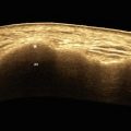
The bladder is normally a smooth, thick-wa lled, anterior pelvic structure that lies posterior to the pubic symphysis that easily distends when filled with anechoic urine. The sex-specific organs lie posteriorly and may appear more echogenic than surrounding structures due to posterior acoustic enhancement from a fluid-filled bladder. The use of Color Doppler on a full bladder may demonstrate the normal, intermittent flow from the ureters into the bladder, termed “ureteral jets ” as shown in Fig. 2.9.

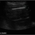
Fig. 2.9
As urine enters the bladder, power Doppler visualizes a ureteral jet in this transverse view
Abdominal Aorta
The first landmark visualized is the spine in the trans verse sub-xiphoid window. The spine appears as a curved hyperechoic surface with acoustic shadows obscuring the posterior portion. The abdominal aorta appears as an anechoic circular structure directly superficial and to the left of the spine. The inferior vena cava sits superficial and to the right of the spine. The celiac trunk is the most proximal vessel visualized branching anteriorly from the aorta. The celiac trunk divides into the splenic artery to the left and the common hepatic artery to the right and sometimes resembles a seagull with spread wings. Immediately distal to the celiac trunk the superior mesenteric artery branches anteriorly and then runs parallel to the abdominal aorta before deviating to the right. The left renal vein can be seen branching from the inferior vena cava and running to the left between the aorta and the superior mesenteric artery. Immediately distal to the superior mesenteric artery, the left and right renal arteries can be seen branching from the lateral sides of the aorta. In some patients the renal arteries will be difficult to visualize. The inferior mesenteric artery is usually too small to be easily identified ultrasonographically. The aorta bifurcates into the left and right common iliac arteries at the level of the umbilicus. Normal anatomy of the aorta is depicted in Fig. 2.10.

Fig. 2.10
(a–d) A diagram of the major branching vessels of the abdominal aorta (a) along with transverse ultrasound views of the celiac trunk (b), superior mesenteric artery (c), and the bifurcation of the common iliac arteries (d). SMA superior mesenteric artery, CT celiac truck, CHA common hepatic artery, SA splenic artery
Gall Bladder
The gallbladder is a cystic structure filled with anechoic bile and demonstrating posterior acoustic enhancement. It is surrounded by a hyperechoic, muscular wall. The gallbladder wall can have several folds and the fundus may even fold back on itself in an anatomic variant known as the “phrygian cap ” as seen in Fig. 2.11. The portal triad, made up of the portal vein, hepatic artery and common bile duct, is visualized just inferior to the gallbladder in the long axis as shown in Fig. 2.12.