, as a function of the location, x, and time, t, is generated over a finite length [− b, b] in the x-direction and [ ] in the y-direction. The normal velocity is assumed to be zero over the remainder of the plane. This type of model is called a rigid baffle model since the element is assumed to be embedded in an otherwise motionless plane, as discussed in Chap. 1. The motion of the element radiates a 2-D pressure wave field
  into an ideal compressible fluid medium that occupies the region
  .
.
As shown in many texts (see [Schmerr], for example) the application of Newton’s law ( ) to a small fluid element yields the equations of motion (for no body forces) of the fluid given by:
 ) to a small fluid element yields the equations of motion (for no body forces) of the fluid given by:
(2.1)
Where  is the density of the fluid,
  is the vector displacement, and the 2-D gradient operator
  , and
, and  are unit vectors in the x– and z-directions, respectively. For an ideal compressible fluid the pressure in the fluid is related to the fluid motion by the constitutive equation
 is the density of the fluid,
  is the vector displacement, and the 2-D gradient operator
  , and
, and  are unit vectors in the x– and z-directions, respectively. For an ideal compressible fluid the pressure in the fluid is related to the fluid motion by the constitutive equation
(2.2)
where  is the bulk modulus of the fluid. The quantity
  appearing in Eq. (2.2) is called the dilatation . Physically, it represents the relative change of volume per unit volume of a small fluid element and it is also called the volumetric strain of the fluid element [Schmerr]. The minus sign is present in Eq. (2.2) because a positive pressure causes a decrease in the volume of a compressible fluid.
 is the bulk modulus of the fluid. The quantity
  appearing in Eq. (2.2) is called the dilatation . Physically, it represents the relative change of volume per unit volume of a small fluid element and it is also called the volumetric strain of the fluid element [Schmerr]. The minus sign is present in Eq. (2.2) because a positive pressure causes a decrease in the volume of a compressible fluid.
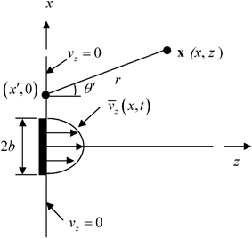
Fig. 2.1
Model of a 1-D element radiating into a fluid with density and wave speed,  , respectively
 , respectively
If one takes the divergence ( ) of both sides of Eq. (2.1) and uses Eq. (2.2), it follows that the pressure
  must satisfy the wave equation:
 ) of both sides of Eq. (2.1) and uses Eq. (2.2), it follows that the pressure
  must satisfy the wave equation:
(2.3)
where the wave speed,  , in the fluid is given by
 , in the fluid is given by
(2.4)
In modeling waves in the fluid, we will assume that all the waves have a harmonic time dependency  so that
 so that
(2.5)
Placing this relationship into Eq. (2.3) shows that  must satisfy the Helmholtz equation
 must satisfy the Helmholtz equation
(2.6)
Alternatively, we can view a solution  of Eq. (2.6) as the Fourier transform (frequency domain spectrum) of a time dependent wave field
  , where
 of Eq. (2.6) as the Fourier transform (frequency domain spectrum) of a time dependent wave field
  , where
(2.7)
and

(2.8)
since if we take the Fourier transform of the wave equation it follows that the transformed pressure  also must satisfy the Helmholtz equation .
 also must satisfy the Helmholtz equation .
We will solve our models of transducer behavior in this and later Chapters for the fields  . Since we will be working almost exclusively with frequency domain wave fields in this book, we will henceforth drop the tilde on our frequency domain variables and simply write fields such as the pressure or velocity as
  or
or  , etc. with the understanding that an additional time dependent term
  is also always present implicitly if we want to recover a time domain solution (see Eq. (2.8)) or if we consider these fields as harmonic wave fields.
 . Since we will be working almost exclusively with frequency domain wave fields in this book, we will henceforth drop the tilde on our frequency domain variables and simply write fields such as the pressure or velocity as
  or
or  , etc. with the understanding that an additional time dependent term
  is also always present implicitly if we want to recover a time domain solution (see Eq. (2.8)) or if we consider these fields as harmonic wave fields.
To solve for the waves generated in the geometry of Fig. 2.1, we first note that the Helmholtz equation has harmonic wave solutions given by

(2.9)
where

(2.10)
and  is the wave number. For the real value of
  given in Eq. (2.10), the solution of Eq. (2.9) represents a plane wave traveling at an angle
  with respect to the z-axis, where
  ,
,  . The imaginary value of
  corresponds to an inhomogeneous wave traveling in the plus or minus x-direction (depending on the sign of
  ) and decaying exponentially in amplitude in the z-direction. Since the waves given by Eq. (2.9) are solutions of the Helmholtz equation, we can also form up a more general solution by simply a superposition of these waves traveling with different values of
  , i.e. we can let
 is the wave number. For the real value of
  given in Eq. (2.10), the solution of Eq. (2.9) represents a plane wave traveling at an angle
  with respect to the z-axis, where
  ,
,  . The imaginary value of
  corresponds to an inhomogeneous wave traveling in the plus or minus x-direction (depending on the sign of
  ) and decaying exponentially in amplitude in the z-direction. Since the waves given by Eq. (2.9) are solutions of the Helmholtz equation, we can also form up a more general solution by simply a superposition of these waves traveling with different values of
  , i.e. we can let
(2.11)
This type of solution is called an angular spectrum of plane waves , although as we have seen it is really a combination of both plane waves and inhomogeneous waves .
We will use this type of solution to represent the waves generated by the element model of Fig. 2.1. If we let  be the Fourier transform of
  (on the plane z = 0) then
 be the Fourier transform of
  (on the plane z = 0) then
(2.12)
and we see that

(2.13)
where

(2.14)
Note that from the equation of motion (Eq. (2.1)) we have

(2.15)
so that

(2.16)
Thus, from Eq. (2.11) we find
(2.17)
where

(2.18)
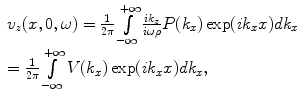
Equation (2.17) shows that  can be treated as a spatial inverse Fourier transform of
  so that from the corresponding forward spatial transform we have
 can be treated as a spatial inverse Fourier transform of
  so that from the corresponding forward spatial transform we have
(2.19)
Since the velocity on z = 0 is known (Eq. (2.13)) the spatial Fourier transform  is also known and we can write the pressure anywhere in the fluid from Eq. (2.11) and Eq. (2.18) as
 is also known and we can write the pressure anywhere in the fluid from Eq. (2.11) and Eq. (2.18) as
(2.20)
Now, Eq. (2.20) is in the form of a spatial inverse Fourier transform of a product of functions  and
and  , i.e.
 and
and  , i.e.
(2.21)
where

(2.22)
But by the convolution theorem [Schmerr] the inverse Fourier transform of a product of transformed functions is the convolution of the functions themselves, so that in this case the convolution theorem gives

(2.23)
where

(2.24)
and

(2.25)

(2.26)
Now, consider Eq. (2.24). This is the inverse Fourier transform of an explicit function and can be shown to be proportional to a Hankel function of zeroth order and type one [1]. Specifically,

(2.27)
where again  is the wave number. Placing these results into Eq. (2.21) then gives
 is the wave number. Placing these results into Eq. (2.21) then gives
(2.28)
where  is the distance from a point
  on the plane z = 0 to a point
  in the fluid (see Fig. 2.1). Since the velocity on the plane z = 0 is given by Eq. (2.13), we find
 is the distance from a point
  on the plane z = 0 to a point
  in the fluid (see Fig. 2.1). Since the velocity on the plane z = 0 is given by Eq. (2.13), we find
(2.29)
in terms of the velocity on the face of the element, which is assumed to be known. Equation (2.29) gives the pressure anywhere in the fluid generated by the motion of the face of the element so it is a complete ultrasonic model for the waves generated by a single element radiating into a single fluid medium.
Physically, Eq. (2.29) represents the wave field of the transducer element in terms of a weighted superposition of cylindrical waves arising from concentrated sources acting over the length of the transducer. This can be seen more explicitly by assuming the distance r to a point in the fluid is many wavelengths away from the element so that kr > > 1. Then, since the Hankel function has the asymptotic value [2]
![$$ H_{0}^{( 1 )}(u)=\sqrt{\frac{2}{\pi u}}\exp [ i(u-\pi /4) ] $$](/wp-content/uploads/2016/05/A314073_1_En_2_Chapter_Equ30.gif)
(2.30)
for u >> 1, Eq. (2.30) becomes

(2.31)
in terms of a superposition of the cylindrical wave terms  over the length of the element.
 over the length of the element.
2.2 Far Field Waves
From the law of cosines (see Fig. 2.2) we have
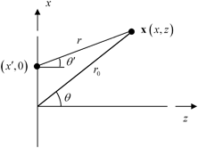
Fig. 2.2
Geometry parameters for defining the far field response

(2.32)
Continuing to keep the high frequency approximation kr >> 1 the far field of the element is defined as the region far enough from the element so that  are valid and we can expand Eq. (2.32) to only first order as
 are valid and we can expand Eq. (2.32) to only first order as
(2.33)
If we place this approximation into Eq. (2.30) we obtain

(2.34)
or equivalently, in terms of the spatial Fourier transform of the velocity field ,

(2.35)
with 

Equation (2.35) shows that in the far field region the element behaves like a concentrated source emitting a single cylindrical wave so we could call this region the cylindrical wave region of the element.
In most cases we will model the motion on the face of an element as if it acted as a piston source, i.e. as if the element had a spatially uniform velocity over the entire length of the element :

(2.36)
In this case the spatial Fourier transform is

(2.37)
and the far field piston element response can be written as

(2.38)
Equation (2.38) shows that in the far field the piston element response has a directivity function,  , where
 , where
(2.39)
This directivity function is strongly controlled by the non-dimensional wave number, kb, as shown in Fig. 2.3. [Note: For brevity of notation in later expressions this kb dependency will be omitted in the argument of  but it should be implicitly understood that it is still present in this and in other directivities that will be discussed in later Chapters.] For a value of kb = 0.314 where the length, 2b, of the element is one tenth of a wavelength,λ, (Fig. 2.3a), the sound radiation of the element is nearly uniform in all directions (
 ) . At kb = 1.57 (element length = one half a wavelength) there begins to be some significant changes in directivity with angle (Fig. 2.3b) but the radiation pattern is still broad. At a value kb = 3.14 (element length = one wavelength) Fig. 2.3c shows that now most of the radiation is in an angular region of
  about the normal to the element and at kb = 9.42 (element length = three wavelengths) the sound is confined primarily to a highly directed beam, with the appearance of small side lobes, as shown in Fig. 2.3d. Most NDE phased array transducers operate at MHz frequencies and with element sizes that are larger than one half a wave length so that directivity of the element plays an important role in the sound field generated and appears as a part of the overall response of an array of elements .
 but it should be implicitly understood that it is still present in this and in other directivities that will be discussed in later Chapters.] For a value of kb = 0.314 where the length, 2b, of the element is one tenth of a wavelength,λ, (Fig. 2.3a), the sound radiation of the element is nearly uniform in all directions (
 ) . At kb = 1.57 (element length = one half a wavelength) there begins to be some significant changes in directivity with angle (Fig. 2.3b) but the radiation pattern is still broad. At a value kb = 3.14 (element length = one wavelength) Fig. 2.3c shows that now most of the radiation is in an angular region of
  about the normal to the element and at kb = 9.42 (element length = three wavelengths) the sound is confined primarily to a highly directed beam, with the appearance of small side lobes, as shown in Fig. 2.3d. Most NDE phased array transducers operate at MHz frequencies and with element sizes that are larger than one half a wave length so that directivity of the element plays an important role in the sound field generated and appears as a part of the overall response of an array of elements .
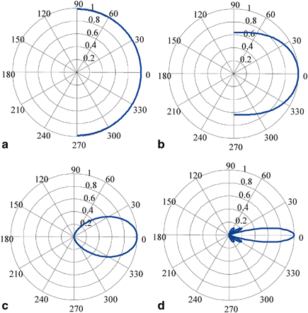
Fig. 2.3
The directivity function for an element of a length  , b
, b  , c
, c  , and d
 , b
, b  , c
, c  , and d
It is customary to define the size of the main “lobe” of the far field sound beam generated by an element in terms of the angle at which the pressure first drops to one half (− 6 dB) of its value along the z-axis  . For the sinc function,
  , this one half value occurs at x = 1.8955 so that from Eq. (2.39) we see the − 6 dB angle is given by
 . For the sinc function,
  , this one half value occurs at x = 1.8955 so that from Eq. (2.39) we see the − 6 dB angle is given by
![$$ {{\theta }_{-6dB}}={{\sin }^{-1}}\left[ 0.6\frac{\lambda }{2b} \right], $$](/wp-content/uploads/2016/05/A314073_1_En_2_Chapter_Equ40.gif)
(2.40)
which always has a root as long as ![$$2b>0.6\lambda $$
” src=”/wp-content/uploads/2016/05/A314073_1_En_2_Chapter_IEq59.gif”></SPAN>. Table <SPAN class=InternalRef><A href=]() 2.1 shows the results for cases (c) and (d) of Fig. 2.3 which agree with the angular patterns shown in Fig. 2.3. Also shown in Table 2.1 are the results for an element that is ten wave lengths long, where it can be seen that the directivity becomes quite small. Large, single element transducers used in NDE applications are normally tens of wavelengths in diameter so that they are highly directional and generate sound beams that are well collimated, i.e. most of the sound propagates normal to the face of the transducer. However, for the smaller elements present in phased array transducers the far field directivity can vary considerably, depending on the size of the elements .
2.1 shows the results for cases (c) and (d) of Fig. 2.3 which agree with the angular patterns shown in Fig. 2.3. Also shown in Table 2.1 are the results for an element that is ten wave lengths long, where it can be seen that the directivity becomes quite small. Large, single element transducers used in NDE applications are normally tens of wavelengths in diameter so that they are highly directional and generate sound beams that are well collimated, i.e. most of the sound propagates normal to the face of the transducer. However, for the smaller elements present in phased array transducers the far field directivity can vary considerably, depending on the size of the elements .
Table 2.1
Directivities of some elements of various sizes
Element size, 2b/λ |  (degrees) (degrees) |
|---|---|
1.0 | 36.9 |
3.0 | 11.5 |
10.0 | 3.4 |
It is important to know when the far field approximation we have been using in this section is valid. Recall, in Eq. (2.32) we expanded the radius r to only first order Eq. (2.33) which led us to the explicit far field results. Let us go back to Eq. (2.32


Stay updated, free articles. Join our Telegram channel

Full access? Get Clinical Tree


