, Foster D. Lasley2, Indra J. Das2, Marc S. Mendonca2 and Joseph R. Dynlacht2
(1)
Department of Radiation Oncology, CHRISTUS St. Patrick Regional Cancer Center, Lake Charles, LA, USA
(2)
Department of Radiation Oncology, Indiana University School of Medicine, Indianapolis, IN, USA
What Is Advanced Treatment Planning?
This chapter focuses on advanced treatment planning techniques:
Imaging techniques
Immobilization techniques
Treatment Planning and Evaluation techniques
See Chapt. 9 for details on basic treatment planning:
Irregular surface compensation
Wedges
Bolus
Field matching (gap calculation)
ICRU reference dose definition
2D Radiography
Plain film must be selected based on:
Energy (kV film is very different from MV film)
Sensitivity (is it a 2 cGy port film, or a 200 cGy whole fraction verification?)
Electronic imaging is performed by:
Fluoroscopy – Conversion of X-rays to visible light.
Ionization chamber array – Limited resolution.
Amorphous silicon panel – Most modern technology.
Real time imaging may be performed with fluoroscopy or by setting a digital flat-panel to “fluoro” mode.
Diagnostic-energy radiographs are characterized by:
Kilovolts peak (kVp): maximum X-ray energy. Increasing kVp increases exposure and penetration but decreases contrast.
Milliamp-seconds (mAs): product of tube current and time. Increasing mAs increases exposure only.
Magnification: image on film is always larger than true size, because of beam divergence.

(12.1)
FFD = Focus-Film Distance
FAD = Focus-Axis Distance
Computed Tomography (CT)
Measures Hounsfield units (HU), can be converted to electron density for treatment planning.
Air = −1,000 HU, Water = 0 HU, Bone ≈ 1800 HU.
Electron density can be used for dose calculation.
Limited bore size and field of view (FoV): (Fig. 12.1).
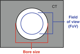
Fig. 12.1
CT bore size and FoV. The field of view is always significantly smaller than the bore size, so if a patient barely fits into a machine you will not obtain an accurate image of the patients.
Finite slice thickness (typically ranges from 1 to 5 mm).
Only images the axial plane – sagittal and coronal planes are digitally reconstructed and less accurate.
High resolution in the axial plane.
Low resolution in the craniocaudal direction.
Susceptible to metal artifact.
Susceptible to motion artifact, unless 4DCT is used.
Cone Beam CT (CBCT)
Obtained using rotation of a 2D imager.
Unlike regular CT, CBCT has equal resolution in all directions. Compared to regular CT:
Lower resolution in axial plane.
Higher resolution in craniocaudal plane.
If the desired FoV is smaller than the imaging panel, it can operate in whole fan mode.
CBCT images the entire field at all times.
Requires a 180° rotation minimum.
If desired FoV is larger than the imaging panel, can operate in half fan mode to double the FoV:
Half of the field is imaged at any given time.
Requires a 360° rotation minimum (Fig. 12.2).
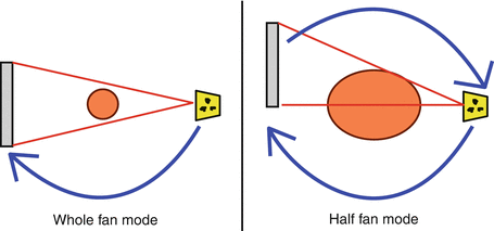
Fig. 12.2
CBCT fan modes. Whole fan mode is used to image small fields, while half fan mode is used to image large fields.
Digital Tomosynthesis
Uses the same principle as CBCT but attempts to synthesize a 3D image with less than 180° of rotation.
The larger the angle of rotation, the more accurate the image. (at 180+ degrees it becomes a CBCT).
Smaller rotational angles cause more artifacts.
Tomosynthesis is used to obtain CT-like images with shorter imaging time and less imaging dose.
Magnetic Resonance Imaging (MRI)
Measures proton spin using magnetic and radiofrequency fields.
Does not give direct electron density information.
Not limited to the axial plane; can take true sagittal and coronal images.
True 3D sequences have equal resolution in all planes. Ideal for image fusion.
T1: water dark, fat bright. Brain is “right side up”. (white matter white, grey matter grey).
T2: water bright, fat dark. Brain is “upside down”. (white matter grey, grey matter white).
T2FLAIR: water dark, fat dark. Brain is “upside down”.
Other: many, many different MR imaging sequence modalities.
Very limited FoV, different MR coil for each part of the body.
Much worse metal artifact. (even for MR-safe metals).
Much worse motion artifact.
Due to long scan times, patient has more time to move.
Image Resolution
Plain film and electronic film have sub-mm resolution, equal in all directions.
Fluoroscopy generally has lower resolution than static film.
CT has very high resolution in the axial plane, but much lower resolution craniocaudal.
Axial resolution = mm or sub-mm.
Craniocaudal resolution = slice thickness, which is usually several mm.
MRI has good resolution and is capable of producing 3D sequences with equal resolution in all planes.
However, MR images are limited by motion artifact.
Windowing and Leveling
CT and MR data have a very broad range of intensities.
If the full range was displayed on screen it would look “washed out”.
Window and Level allow one to select a range of intensities to display on screen.
Level = the center of the intensity range.
Ex: a CT with L = 50 will display HU = 50
Stay updated, free articles. Join our Telegram channel

Full access? Get Clinical Tree


