1 Anatomy and Imaging of the Shoulder Joint
Macroscopic Functional Anatomy
The head and the glenoid fossa articulate in the shoulder joint (glenohumeral joint). Functionally, it is a ball-and-socket joint that enables movement in three degrees of freedom. The shoulder is the most mobile of the major joints. Its high mobility, together with its limited osseous embracement accounts for its high rate of injury.
Osseous Structures
Humerus
 Articular surface of the humeral head covered hemispherically with hyaline cartilage
 Rotation of the humeral head around a central point in the depth of the head
 Important markers of the proximal humerus: major and minor tuberosities as well as bicipital groove
 Anatomical neck: Transition of the proximal humerus to the humeral head
 Surgical neck: Frequent fracture site
Scapula
 Gliding and rotation of the scapula on the thoracic surface with arm movement
 The glenoid fossa is perpendicular to the body of the scapula
 The osseous glenoid fossa is markedly smaller than the humeral head (ratio about 1:4)
 According to Bigliani (1982), three different acromial types can be observed in the coronal plane:
– Type I: Flat acromion
– Type II: Curved acromion
– Type III: Hooked acromion with inferior nose
Clavicle
 Flat, sinuous, bridging the upper ribs
 Medial articulation with the sternum at the sternoclavicular joint (SC joint)
 Lateral connection with scapula with the acromioclavicular joint (AC joint)
Soft Tissues
Glenoid Labrum
Since the incongruent osseous articular surfaces alone cannot provide structural and functional integrity of the shoulder joint, it is largely stabilized by the glenoid labrum.
 Circular enlargement of the articular surface
 Fibrous cuff of fibrocartilage reinforcing the joint capsule
 Vascular supply through capsular vessels
 “Transitional zone” (hyaline cartilage) between labrum and osseous glenoid fossa
 Four labrum segments: anterosuperior and posterosuperior, as well as anteroinferior and posteroinferior quadrants
 Surgical localization of the labral lesions following the dial of the clock: right anterior positions 12 to 6 o’clock (left posterior positions 12 to 6 o’clock!)
 Numerous normal variants of the labrum (see Chapter 2, Traumatology)
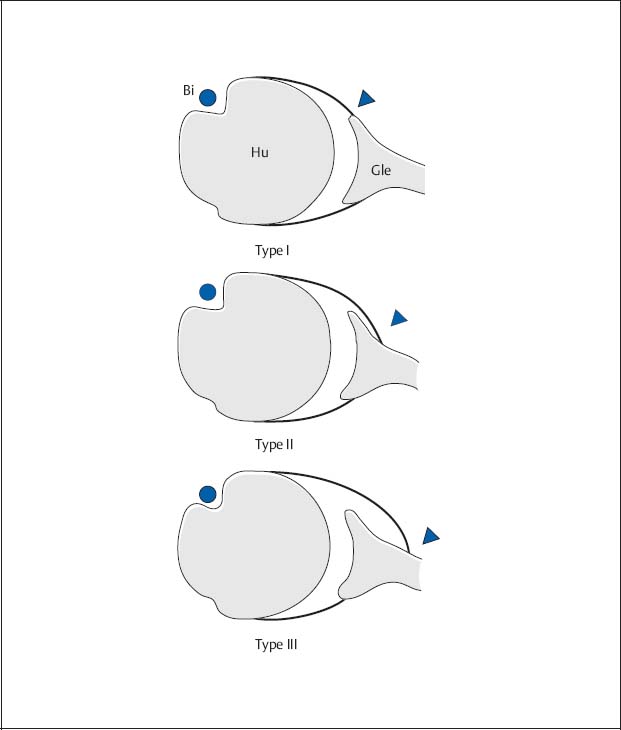
Fig. 1.1  Types of capsular insertion according to Moseley and Övergaard (1962).
Diagram of the different insertions of the anterior capsule as seen on the axial plane (arrowheads).
Bi | Biceps tendon |
Hu | Humerus |
Gle | Glenoid process |
Capsuloligamentous System
The capsuloligamentous system contributes relatively little to the static stability of the shoulder. The joint is further supported by an intra-articular negative pressure.
 Capsular insertion with fibrous and synovial component in the region of the osseous glenoid fossa
 Three glenohumeral ligaments (superior, medium, and inferior glenohumeral ligaments) to enforce the anterior capsule
 Wide variability of course, insertion, and caliber of the three ligaments
 The inferior ligament is most important for shoulder stability
 Variable anterior capsular insertion at the glenoid fossa; according to Moseley and Övergaard (1962), three capsular insertions can be distinguished in the axial plane (Fig. 1.1):
– Type I: Insertion at the tip or basis of the anterior labrum
– Type II: Insertion of the capsule not more than 1 cm medial to the labrum
– Type III: Insertion of the capsule more than 1 cm medial to the labrum
 Type III should predispose to or be the result of anterior dislocation
Musculature of the Rotator Cuff
Since osseous and ligamentous support is inadequate, stability is achieved by soft tissues. Dynamic stability is primarily provided by the muscles of the rotator cuff together with the deltoid muscle.
 Four muscles: Anteriorly the subscapular muscle (origin at the minor tuberosity), posteriorly the supraspinatus muscle (origin at the major tuberosity), the infraspinatus muscle and the teres minor (origin at the major tuberosity)
 Fibrous “tendon cap” of the rotator cuff around the humeral head
 “Critical zone” within the tendon of the supraspinatus muscle (1–1.5 cm proximal to its origin) presumably predisposes to degeneration with subsequent rupture
 Additional stabilization of the joint provided by muscular compression through pull of the rotator cuff
Bursae of the Shoulder Joint
Several bursae (fluid-containing sacs lined with synovial membrane) serve as gliding layers to facilitate free motion of the shoulder joint and partially communicate with the joint cavity.
 The subacromial bursa and subdeltoid bursa often communicate with each other, but usually not with the joint capsule (important for rotator-cuff tears!)
 The subtendinous bursa of the sub-scapular muscle and the subcoracoid bursa communicate with the joint anteriorly
 Normal bursae are not visualized by conventional radiology, only by ultrasound (US), computed tomography (CT), and magnetic resonance imaging (MRI)
Conventional Radiology
Standard Projections
Like all other joints, the shoulder is first examined by obtaining a baseline study consisting of two views perpendicular to each other. Many special projections are available for different clinical questions (Table 1.1), but their diagnostic contribution has diminished following the introduction of CT and MRI.
Table 1.1  Recommended radiographic projections of the shoulder joint (please refer to text for technical factors)
Clinical question | Projections |
|---|---|
Baseline |
|
Degeneration |
|
Special impingement |
|
General trauma |
|
Impaired mobility |
|
Dislocation |
|
Special Bankart lesion |
|
Special Hill-Sachs defect |
|
AC joint |
|
 AP view
 Axial view
 AP view
 Axial view
 90° abduction view
 Schweden stage I–III
 View of the intertubercular groove
 Supraspinatus outlet view
 Rockwood view
 AP view
 Axial view
 Transthoracic view
 Y-projection
 Velpeau view
 AP view
 Axial view
 West Point view
 Glenoid rim view according to Bernageau
 Apical oblique view
 AP view in 60° internal rotation
 Stryker view
 Hermodsson view
 AC joint view AP
 AC joint view AP with weight bearing
 Supraspinatus outlet view
 Rockwood view
Anteroposterior View/Tangential View of the Glenoid Fossa
Caution: The joint space is superimposed on the straight anteroposterior (AP) view!
Indication
Initial workup for suspected
 Fractures (location and extent, determination of fracture type, orientation of fracture lines, articular involvement, position of fracture fragments)
 Dislocations
 Inflammatory conditions
 Degenerative changes
 Neoplasms
Technique
 Shoulder in contact with the cassett
 Patient sitting with the arm in neutral position (palms up)
 Caudal angulation of the central ray by about 20°
 Centered to the coracoid process
Alternatively:
 Patient lying with elevation of the contralateral shoulder
 Caudal angulation of the central ray
 Centered to the coracoid process
Glenoid Tangential View
Orthograde projection of the joint space free of superimposition
 The patient is rotated 30–45° to the right (→ scapula parallel to the cassette!)
 As on the AP view, centered to the coracoid process
Radiographic Anatomy (Fig. 1.2)
 Visualization of the glenohumeral articulation: narrow ovoid or linear (orthogonal) fossa
 Apex of the coracoid process in projection of the humeral head
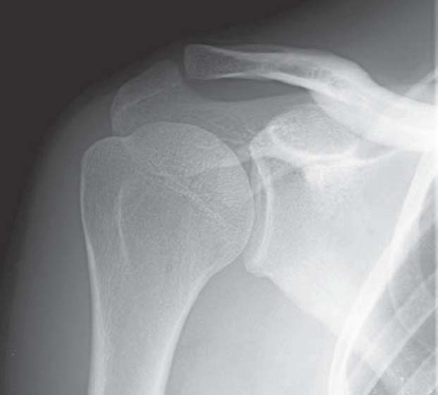
Fig. 1.2  AP view
As initial view of the glenohumeral articulation with the humerus superimposed on the glenoid fossa. The joint space is not exactly seen tangentially.
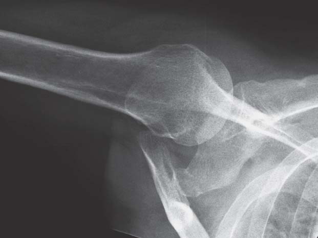
Fig. 1.3  Axial view.
Location of the humeral head in relation to the glenoid process with the upper arm in 90° abduction, as second plane of the diagnostic workup.
Alternatively:
Craniocaudal Projection
 Patient sitting
 Position the arm with the flexed elbow lateral on the examination table
 Cassette placed in the axilla, better “saddle (curved) cassette”
 Perpendicular craniocaudal central ray centered to the joint
Axial View
Caution: Axial view is contraindicated if an acute fracture or dislocation is suspected!
Indication
Second plane of the initial view
Technique
Caudocranial Projection
 Patient supine, head and shoulder slightly elevated
 About 90° abduction of the arm, external rotation of the upper arm with flexion of the elbow
 Place the cassette against the top of the shoulder
 Perpendicular craniocaudal central ray parallel to the thoracic wall centered to the axilla
Radiographic Anatomy (Fig. 1.3)
 Position of the humeral head relative to the glenoid fossa
 Superimposition of the AC joint on the humeral head
Special Projections for Impingement
Since the subacromial space and bicipital (intertubercular) groove are inadequately visualized on both standard views, the following views are used.
AP View in Three Different Rotations (Impingement Series I–III)
Indication
 Localization of pathological processes, such as interarticular loose bodies or calcifications of the rotator cuff
 Visualization of fractures
Technique
Patient positioning and projection same as in AP standard projection. In addition:
 Internal rotation with elbow in flexion and abduction, hand in supination (I)
 External rotation of the slightly abducted arm with the hand in supination (II)
 External rotation and elevation with 90° abduction of the arm, rectangular flexion of the elbow (III)
Radiographic Anatomy
 Visualization of the humeral head and joint space free of superimposition
 Subacromial space and minor tuberosity (I and II)
 Acromion superimposed on the humeral head, visualization of the AC joint (III)
90° Abduction View
Indication
 Visualization of glenohumeral mobility
 Visualization of the AC joint free of superimposition
Technique
 Patient standing parallel to the cassette
 90° abduction of the arm, flexion of the elbow
 AP projection
 Centered to coracoid process
Radiographic Anatomy (Fig. 1.4)
 Superimposed humeral head and acromion
 Direct visualization of the AC joint space
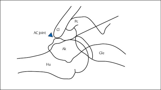
Fig. 1.4  View in 90° abduction (diagram)
Visualization of the humeral head (Hu) superimposed on the acromion (Ak), unobstructed projection of the AC joint space (arrowhead).
Cl | Clavicle |
Gle | Glenoid process |
Pc | Coracoid process |
View of the Intertubercular (Bicipital) Groove
Caution: Requires exact tangential projection of the groove; possibly fluoroscopic guidance.
Indication
 Visualization of the intertubercular (bicipital) groove free of superimposition
Technique
Craniocaudal Projection
 Patient bending over the examination table
 Flexion and supination of the arm resting on the table (→ humerus and forearm form an angle between 75° and 80°)
 Cassette placed horizontally on the forearm
 Palpation of the sulcus and its course marked on the skin
 Craniocaudal central ray perpendicular to the skin marks
Alternatively:
Caudocranial Projection
 Patient supine
 Cassette placed against the top of the shoulder
 Arm slightly abducted and externally rotated
 Craniocaudal projection through anterior margin of the humerus
 Central ray parallel to the longitudinal axis of the upper arm (→ following the course of the groove)
Radiographic Anatomy
 Intertubercular (bicipital) groove seen as indentation between both tuberosities
Supraspinatus Outlet View
Indication
Suspected subacromial pathology:
 Visualization of the coracoacromial pathology (supraspinatus outlet)
 Visualization of possible subacromial osteophytes
 Identification of the acromion types according to Bigliani (see Osseous Structures/Scapula)
Technique
 Patient in the oblique position, standing or sitting
 Cassette perpendicular to the body of the scapula and parallel to the glenoid fossa
 Mediolateral projection along the axis of the scapular spine
 Central ray craniocaudally angled by 10–15° and centered to the AC joint
Radiographic Anatomy
 Body of the scapula free of superimposed ribs
 Humeral head in projection of the Y of the scapula (short limb of the Y: acromion and coracoid process; long limb of the Y: scapular body)
 Acromion as “roof” of the subacromial space
Rockwood View
Indication
Suspected subacromial pathology:
 Visualization of inferior acromial osteophytes
 Calcifications of the coracoacromial ligament
Technique
 As in the AP view, but 30° caudal angulation of the central ray
Radiographic Anatomy
 Visualization of the subacromial space and the anteroinferior acromion
Special Projections for Restricted Mobility
If pain-restricted mobility (dislocation, fracture) contraindicates an axial view, the following alternative views should be considered.
Transthoracic View
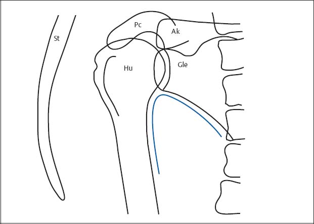
Fig. 1.5  Transthoracic view (diagram)
Humerus (Hu) in projection between spine and sternum (St) (the superimposed ribs have been deleted for the sake of clarity). The auxiliary line according to Moloney (1983) is drawn as a blue line.
Gle | Glenoid |
Ak | Acromion |
Pc | Coracoid process |
Caution: Superimposition can interfere with the interpretation.
Indication
 Second plane for the motion-restricted shoulder
 Evaluation of the joint in (subcapital) fractures of the humerus and shoulder dislocations
Technique
 Patient sitting and standing, with slight posterior rotation of the upper body
 Affected shoulder laterally placed on the cassette
 Hanging arm in supination
 Opposite arm raised and placed over the top of the head (→ to be out of the collimation field of the radiographic projection)
 Transthoracic mediolateral projection
 Centered directly below the coracoid process
Radiographic Anatomy (Fig. 1.5)
 Humerus projected between spine and sternum
 Glenoid fossa partially superimposed by the humeral head
 Auxiliary line according to Moloney (1983): The scapulohumeral arch formed by the axillary border of the scapula and humeral shaft follows a smooth, uninterrupted course
Y-Projection (Lateral View of the Scapula According to Neer, Larché)
Indication
 Second plane for motion-restricted shoulder
 Position of the dislocation
Technique
 Patient lateral against the cassette, sitting or standing
 About 30–45° posterior rotation of the affected shoulder
 Mediolateral projection passes behind the thorax parallel to the scapular spine
 Centered to the middle of the scapula
Radiographic Anatomy(Fig. 1.6)
 Acromion as “roof” of the subacromial space
 Humeral head in projection on the Y of the scapula
 Normal position of the humeral head with exact centering to the glenoid fossa
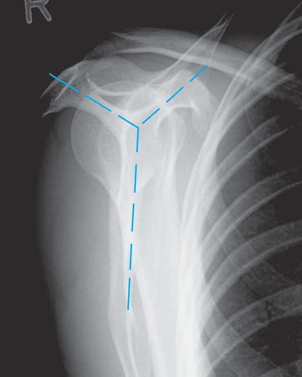
Fig. 1.6  Y-projection
Related posts:
Stay updated, free articles. Join our Telegram channel

Full access? Get Clinical Tree


