, Gila Perk2, Natesa G. Pandian3, Hans-Joachim Nesser4 and Itzhak Kronzon2
(1)
Department of Cardiology, Cardiocentro Ticino, Lugano, Switzerland
(2)
Non-Invasive Cardiology, Lenox Hill Hospital, New York, NY, USA
(3)
Tufts University School of Medicine, Boston, MA, USA
(4)
Department of Medicine Elisabethinen, Teaching Hospital, Linz, Austria
Abstract
Catheter-based percutaneous edge-to-edge repair using the MitraClip device (Abbott Vascular; Abbott Park, IL, USA) is a well-established, effective, and safe procedure that can be utilized in selected patients with mitral regurgitation (MR). The procedure mimics Alfieri’s surgical technique, bringing the anterior and posterior leaflets together from beneath the valve with a metallic stitch. Echocardiographic evaluation before the procedure is of paramount importance in defining the complex morphology of the valve and in detecting target leaflet lesion. Intra-procedural monitoring (i.e. delivery and placement of the clip) is usually performed under fluoroscopic and two-dimensional transoesophageal echocardiography. With the introduction of real-time three-dimensional transesophageal echocardiography (3D TEE), it appeared evident that the new technique would provide unique additional anatomical information both in selecting patients and guiding the procedure. In the selection of patients, the complex spatial structure of the valve is displayed as it actually is, allowing a precise assessment of the culprit as well as of secondary lesions. During the procedure, it has the unique ability to depict the “whole” scenario in which the procedure takes place in a single three-dimensional, real-time, easily understandable perspective. In this chapter we describe the normal mitral valve anatomy as displayed by 3D TEE, the 3D TEE pre-procedural characterization of valve morphology and the growing role of RT TEE in any individual steps of this complex procedure.
Electronic supplementary material
The online version of this chapter (doi:10.1007/978-1-4471-4745-9_3) contains supplementary material, which is available to authorized users.
Catheter-based percutaneous edge-to-edge repair using the MitraClip device (Abbott Vascular; Abbott Park, IL, USA) is a well-established, effective, and safe procedure that can be utilized in selected patients with mitral regurgitation (MR). The procedure mimics Alfieri’s surgical technique, bringing the anterior and posterior leaflets together from beneath the valve with a metallic stitch.
Initially, anatomic inclusion criteria for such a procedure were rigorous, including only patients precisely selected on the basis of valve morphology for which the procedure was thought to be particularly suited. In cases of degenerative mitral disease, only patients in whom the regurgitant jet originated from the A2-P2 segment of the mitral valve, with a flail gap of less than 10 mm and a flail width of less than 15 mm, could undergo the procedure. In cases of functional/ischemic mitral regurgitation, a coaptation length of at least 2 mm and a coaptation depth of no more than 11 mm were required. Moreover, only patients who met the class I indication for surgical intervention were included in the Endovascular Valve Edge-to-Edge Repair Study (EVEREST) I and II trials. These strict criteria excluded anatomic targets other than A2-P2 and, more importantly, excluded high-risk patients, who may benefit most from this therapeutic option.
In many institutions, there is now a growing understanding that the percutaneous approach may provide a valuable treatment option for a significant number of patients who are either unsuitable for surgery or who present an unacceptable surgical risk because of advanced age, comorbidities, or end-stage heart failure. Initial experiences in using the approach without applying the rigid exclusion criteria of the EVEREST I and II trials have shown promising results, suggesting that patients with high surgical risk, severely compromised left ventricular function, and/or complex valvular abnormalities may be suitable candidates for MitraClip therapy.
Echocardiographic evaluation before the procedure is of paramount importance in defining the complex morphology of the valve and in detecting the target leaflet lesion. Intraprocedural monitoring (i.e., delivery and placement of the clip) is usually performed under fluoroscopy and two-dimensional transesophageal echocardiography (2D TEE). Fluoroscopy is used primarily to assess the opening angle of the clip arms but plays a lesser role in steering and positioning the clip. Conversely, 2D TEE has been used as the primary imaging modality for guiding the various steps of the procedure. In particular, 2D TEE has been shown to be essential for transseptal puncture guidance, optimal clip positioning, and assessment of the severity of mitral regurgitation before and after final deployment of the clip.
With the introduction of real-time three-dimensional transesophageal echocardiography (RT 3D TEE), it has become evident that the new technique can provide unique additional anatomic information for both patient selection and guidance of the procedure. In the selection of patients, the complex spatial structure of the valve is displayed as it actually appears, allowing a precise assessment of the culprit lesion and secondary lesions. During the procedure, 3D TEE is uniquely able to depict the whole setting in which the procedure takes place (i.e., the mitral valve, left atrium, interatrial septum, and long segments of catheter moving through these structures) in a single, easily understandable 3D perspective in real time. However, the lack of real-time 3D color imaging and the relatively low frame rate prevent the use of 3D TEE in crucial steps such as the alignment of the delivery system to the origin of the regurgitant jet or the leaflet’s capture.
This chapter describes the normal mitral valve anatomy as displayed by 3D TEE, the 3D TEE preprocedural characterization of valve morphology, and the growing role of RT 3D TEE in individual steps of this complex procedure.
3.1 Anatomy of Mitral Leaflets on 3D TEE
Three-dimensional TEE provides the most accurate anatomic vision of mitral valve leaflets. To acquire 3D TEE imaging of the mitral valve, any echocardiographic 2D TEE plane that permits full visualization of the mitral valve can be used (e.g., bicommissural view or view of left ventricular outflow tract on four-chamber view). Currently, the valve can be viewed in real time using both “zoom” modality and live 3D “narrow volume.” With the zoom modality, the truncated pyramidal data set can be enlarged to include the entire mitral valve, but this occurs at the cost of a frame rate as low as 5–6 frames per second. The pyramidal beam of the live 3D is set at 50° × 30°, an angle that usually is not enough to include the entire valve, but new developments allow electronic enlargement of the pyramidal beam in both lateral and elevation planes, and a pyramidal data set able to embrace the entire mitral valve (full-volume single beat) can be obtained with a frame rate as high as 9–10 frames per second.
Once the 3D image has been acquired, the valve can be seen from various perspectives. The most intuitive and informative view remains the atrial perspective (the so-called surgical view). This view is obtained by rotating the image so that the aorta is positioned at about 12 o’clock on an imaginary clock face, with the left atrial appendage and the lateral commissure on the left (at about 9 or 10 o’clock) and the medial commissure on the right (at about 3 o’clock) (Fig. 3.1). Until the advent of 3D echocardiography, such a perspective was not possible.
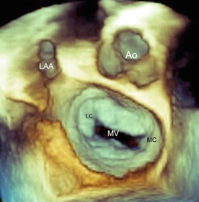
Fig. 3.1
Three-dimensional transesophageal echocardiography (3D TEE) image of the normal mitral valve (MV) from a “surgical” view. The aorta (Ao) is positioned at 12 o’clock; the lateral commissure (LC) and left atrial appendage (LAA) are sited on the left of the MV, at about 9–10 o’clock; and the medial commissure (MC) is on the right, around 3 o’clock
In the “surgical” view, the mitral valve annulus, scallops, and commissures are visualized in a way similar to what is observed by a cardiac surgeon in the operating room when inspecting the mitral valve from the left atrium. From this perspective, many astonishing particulars of valve anatomy can be seen in vivo. It is well known that two commissures divide the valve into two leaflets (the anterior or aortic leaflet and the posterior or mural leaflet). However, these commissures do not actually reach the annulus. A strip of valve tissue provides continuity between the anterior and posterior leaflets, so from a strictly anatomic point of view, it can be said that the mitral valve is formed by a single veil (Fig. 3.2).
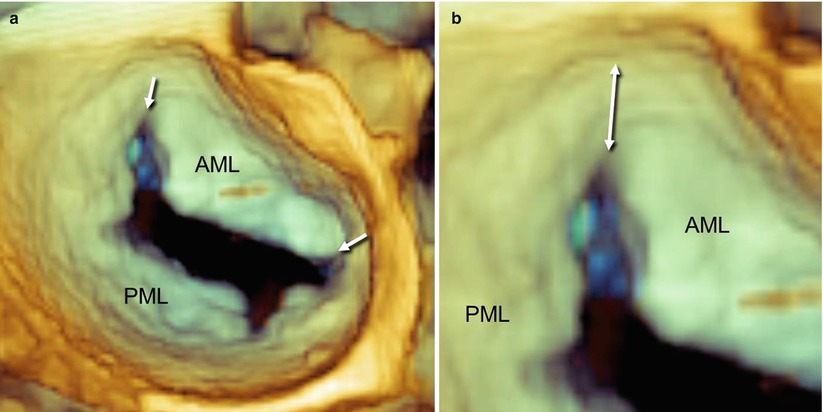
Fig. 3.2
A normal mitral valve viewed on 3D TEE from a “surgical” view. (a) The arrows point to the commissures, which divide the anterior mitral leaflet (AML) from the posterior mitral leaflet (PML). (b) A magnified 3D image shows valve tissue (double-headed arrow) between the commissure and the annulus
In some valves, this tissue continuity has a Y-shaped configuration and forms a small commissural scallop. These commissural scallops are attached to the annulus, and their free edge is supported by a few fanlike chordae. From a functional point of view, these small commissural scallops facilitate coaptation between the anterior and posterior leaflets (Fig. 3.3).
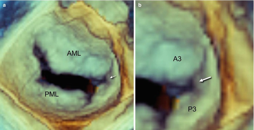
Fig. 3.3
A normal mitral valve viewed on 3D TEE from a “surgical” view. (a) The arrow points to a small commissural scallop, which provides continuity between the anterior and posterior leaflets. (b) Magnified imaging of panel a shows the Y-shaped configuration of the commissural scallop (arrow)
The anterior leaflet extends deeper into the left ventricle than does the posterior leaflet, but it occupies only one third of the annular circumference. Conversely, the posterior leaflet is shorter but attaches to the posterior annulus for the remaining two thirds. Thus, the surface area of both leaflets is equivalent.
The free margin of the posterior leaflet has two indentations that divide the leaflet into three segments called scallops: lateral or P1, central or P2, and medial or P3. By convention, the corresponding areas of the anterior leaflet are named A1, A2, and A3 even though the free edge has no indentations at all (Carpentier’s classification). The indentations are the normal anatomic configuration of the mitral valve and allow a greater opening in diastole. Carpentier’s classification facilitates valve analysis and is most commonly used (Fig. 3.4).
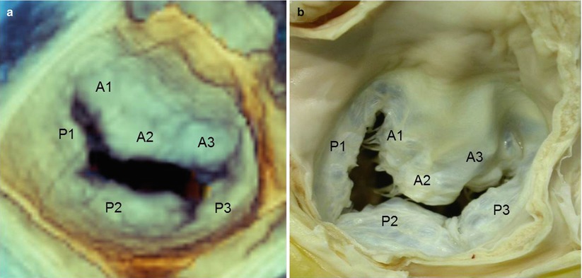
Fig. 3.4
(a) Real-time 3D TEE image of a normal mitral valve from a “surgical” view, showing Carpentier’s classification (see text). (b) An equivalent anatomic specimen (Courtesy of Edgardo Bonacina, Niguarda Hospital, Milan, Italy)
This subdivision does not always match anatomic reality, however. In some individuals, the indentations are virtually indiscernible, so that the posterior leaflet has no anatomically identifiable scallops; in others, more than three scallops can be identified (Fig. 3.5).
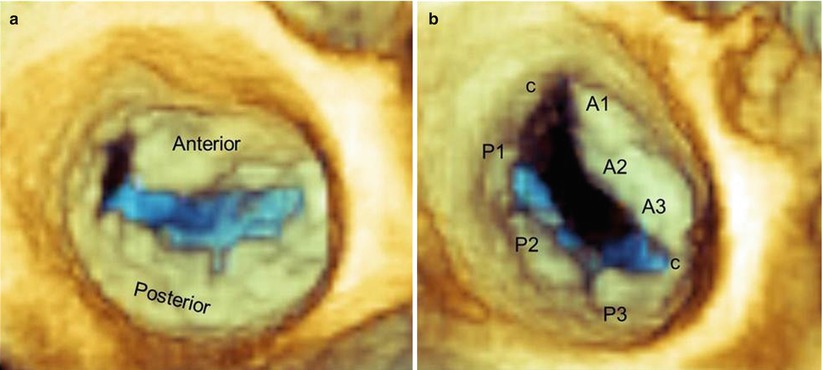
Fig. 3.5
Real-time 3D TEE images of normal mitral valves from a “surgical” view, showing a valve with virtually no scallops (a) and a valve with two additional commissural scallops (c) (b)
In systole, the atrial surface of the leaflets may not appear completely flat: Slight bulging of both anterior and posterior leaflets into the left atrium can frequently be noted in functionally normal valves.
3.2 Preprocedural Assessment of Valve Morphology
According to the etiology, mitral regurgitation (MR) can be divided into two broad categories: degenerative (or primary), in which one or more components of the mitral valve apparatus are deranged, and functional (or secondary), in which MR is due to geometric changes of the left ventricle.
3.2.1 Degenerative Mitral Valve Disease
Degenerative mitral valve disease is a common disorder affecting the tissue of the valve. In clinical practice, a wide spectrum of lesions can be seen, from an isolated chordal rupture involving a single segment of the valve to a complex multiscallop prolapse involving one or both leaflets. The most extreme forms of this spectrum correspond to a “pure” fibroelastic deficiency (FED) and “ultimate” Barlow disease. FED, a condition associated with fibrillin deficiency, often leads to posterior leaflet prolapse and occasionally a flail leaflet, owing to rupture of one or more thinned and elongated chordae. The prolapsed tissue may be normal or, in advanced stages, may have an accumulation of mucopolysaccharides, making the diseased segment of the valve similar to that seen in Barlow disease. The key difference between FED and Barlow disease is the fact that in the FED, the noninvolved segments are normal (or even thinner than normal), with a translucent appearance. In Barlow disease, multiple segments are always affected; the condition ranges from the so-called fruste forme, in which some segments of the valve are still normal, to an extensive involvement of the entire valve. The involved segments are thickened and elongated through myxomatous changes in their medial layer.
There is no doubt that RT 3D TEE is a remarkably reliable technique for defining the complex anatomy of the mitral valve in patients scheduled for valve repair using the MitraClip. It provides in real time the most realistic representation of valve pathology. The fact that the valve in a beating heart can be seen in a 3D format from countless perspectives makes this technique superior to any other imaging technique. For some aspects of mitral valve evaluation, this “dynamic” anatomy is more informative than the surgical inspection of an empty, nonbeating heart. Figures 3.6, 3.7, and 3.8 show the importance of the “surgical” view as well as other “nonsurgical” views for a detailed anatomic assessment. (See also Videos 3.1, 3.2, and 3.3.) In particular, some nonsurgical views may reveal de novo small prolapses or may better clarify prolapses that are not well defined from a surgical perspective. In the surgical perspective, prolapsing segments can be distinguished from nonprolapsing tissue because of the different shades of color that are produced by a specific algorithm, which “illuminates” the image from a virtual source of light sited on the observer’s head. Thus, prolapsing tissues, which protrude into the atrial cavity when seen from above (surgical view), assume brighter shades of beige than the surrounding nonprolapsing segments. We have found that this view is relevant for large prolapses, where differences in shades of color are evident and easily appreciated. In small prolapses, however, such differences are less pronounced, and the prolapse may be difficult to recognize. Conversely, when the valve is seen from other perspectives (in particular from perspectives that are oblique or tangential to the mitral plane), the same algorithm that produces shadowing enhances the edges of prolapsing tissues, making even small prolapses easily distinguishable. Any segment or scallop of mitral leaflets can therefore be independently analyzed from the peculiar perspective that best enhances its morphology (“segment-oriented” approach).
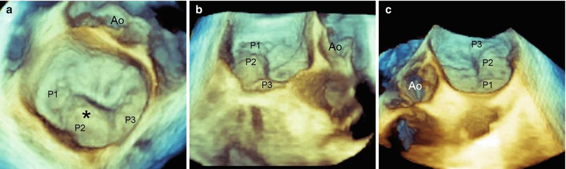
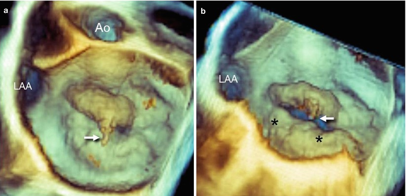
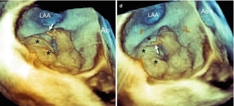
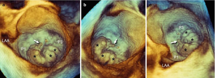
Fig. 3.6
(a) An RT 3D TEE image of a mitral valve from a “surgical” view, showing the main lesion (asterisk) at the level of P2 (see also Video 3.1). However, the prolapses of P1 and P2 are not clearly distinguishable. (b, c) By using perspectives nearly tangential to the valve plane from either a right (b) or left (c) perspective, the edges of prolapsing tissues are enhanced, facilitating the identification of the small P1 (panel b) and P3 (panel c) prolapse (see also Videos 3.2 and 3.3).Ao aorta
Fig. 3.7
(a) RT 3D TEE imaging of the mitral valve from a “surgical” view shows a flail of A2 with a rupture of one chorda (arrow). (b–d) From other perspectives, it is evident that some segments of the posterior leaflet also are prolapsing (asterisks). Ao aorta, LAA left atrial appendage
Fig. 3.8
(a) RT 3D TEE of the mitral valve from a “surgical” view shows a large P2 prolapse with a rupture of chorda (arrow). The prolapse has multiple lobes (asterisks). Although the P2 includes a large part of the posterior leaflets, it is evident that both P1 and P3 are relatively normal, as is the anterior leaflet. (b, c) The other perspectives confirm the involvement of a large P2 and the normal appearance of the other two scallops
A dedicated perspective tangential to and “in front” of the prolapsing leaflet may also display the “true” anatomic regurgitant orifice viewed en face. The anatomic regurgitant orifice may have different configurations (from rounded to elliptical) and can be measured either by a multiplanar reconstruction format or directly on 3D images (Fig. 3.9). Visualizing the site, size, and shape of the anatomic regurgitant orifice may become relevant for planning the strategy to be used in clipping the regurgitant orifice. For instance, a round orifice, as shown in panel A of Figure 3.9, may require a single clip, but an elongated, elliptical orifice, as shown in panel B and Video 3.4, may require more than one clip.
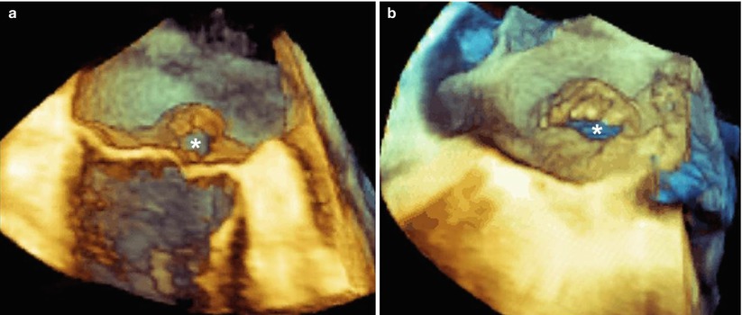
Fig. 3.9
(a) This 3D TEE image shows a mitral valve with a flail of P2. A perspective tangential to the leaflets may display the round-shaped regurgitant orifice (asterisk). (b) This 3D TEE image shows a mitral valve with a flail of A2. In this case, the perspective shows an elliptical regurgitant orifice (asterisk) (see also Video 3.4). The site, size, and shape of the orifice may have relevance in planning the strategy of a mitral clip procedure
3.2.1.1 Selection Criteria in Degenerative Mitral Valve Disease
In degenerative mitral valve disease, case selection is probably the most important determinant of success for the MitraClip procedure. Entry criteria were described first by Feldman and colleagues in their first EVEREST trial. Classically, all patients should have moderate (3+) or severe (4+) MR, as assessed formally by quantitative and qualitative 2D transthoracic and transesophageal echocardiography. Preprocedural echocardiographic criteria for anatomic suitability include flail gap distance (i.e., vertical separations between anterior and posterior leaflets where the gap is the largest) and flail width from the transgastric short-axis view. The origin of the MR jet ideally should be from the central portion of the valve, and the remaining mitral valve effective orifice area should be greater than 4 cm2, as there is a small but inevitable reduction in valve area on the transformation to a double orifice.
With 2D TEE, the flail gap may be incorrectly measured if the longitudinal plane foreshortens the ventricle, and flail width from the transgastric view may be difficult to measure. The same measurements can be taken with 3D TEE either in multiplanar reconstruction or (with a new release) directly on the 3D image. Using 3D TEE, the width of the prolapsing segment can be accurately measured from the surgical view, and the highest point of the prolapsing tissue can be detected from a tangential perspective and measured in longitudinal view, after cropping of the leaflet perpendicularly to this point (Fig. 3.10).
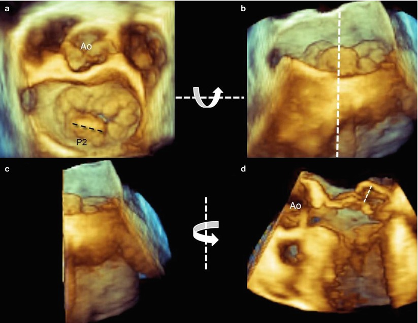
Fig. 3.10
(a) Using 3D TEE, the width of prolapsing tissue can be measured easily from a “surgical” view (dotted line). (b) To visualize the prolapsing tissue protruding into the left atrium, the volumetric data set is rotated down-up around the x-axis (curved arrow) to obtain a tangential view. The volumetric data set is then cropped with a longitudinal plane passing through the highest point of the prolapse visualized from a posterior perspective (dotted line). (c, d) The right half of the data set is then rotated from left to right around the y-axis (curved arrow) and the highest flail gap is measured (dotted line)
Analysis after processing, which involves manually tracing in multiple planes around the axis perpendicular to the mitral annular plane, using custom software (QLAB Mitral Valve Quantification [MVQ]; Philips; Andover, MA, USA), allows a color-coded 3D-rendered surface that resembles a topographic map of the mitral leaflets. The software is able to automatically generate several quantitative parameters, including annular dimensions and geometry and the leaflets’ surface area, billowing volume, and height (Fig. 3.11). Whether these complex quantitative parameters may have a role in planning the procedure is not yet established.
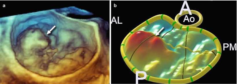
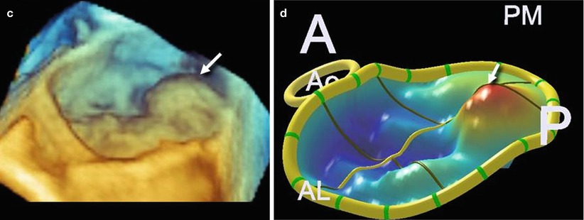
Fig. 3.11
(a, b) A 3D TEE image showing a large prolapse involving P1 (arrow) and the corresponding 3D-rendering color-coded image. (c, d) A 3D TEE image showing a large prolapse involving P3 (arrow) and the corresponding 3D-rendering color-coded image
3.2.2 Functional Mitral Regurgitation
Functional mitral regurgitation (FMR) is caused by regional or global dysfunction of the left ventricle (LV) without apparent valve leaflet pathology. Long-lasting dysfunction may result in secondary degenerative lesions, such as an increase in the thickness or surface area of leaflets.
The most common causes of FMR are ischemic myocardial disease, idiopathic dilated cardiomyopathy, and end-stage ischemic cardiomyopathy. The mechanism of FMR is the tethering of the mitral valve leaflet during systole, caused either by regional ventricular dysfunction (asymmetric valve tethering) or by global dysfunction (symmetric valve tethering).
FMR due to asymmetric valve tethering results from dyskinesis of the myocardial wall with an apical and lateral displacement of one papillary muscle (PM). The distance between the PM tip and the annulus increases, drawing the corresponding leaflet segment into the ventricle and restricting its motion towards the closure. The posteromedial PM is the most frequently involved, producing a systolic restricted motion of the medial half of P2 and the entire P3, as well as some restriction of the medial half of A2 and the entire A3. Imaging with 3D TEE may visualize the site, size, and shape of the anatomic regurgitant orifice either from the classic “surgical” view (Fig. 3.12) or from a ventricular perspective (Fig. 3.13). The site of the regurgitant orifice can be confirmed by 3D TEE color Doppler (Fig. 3.14).
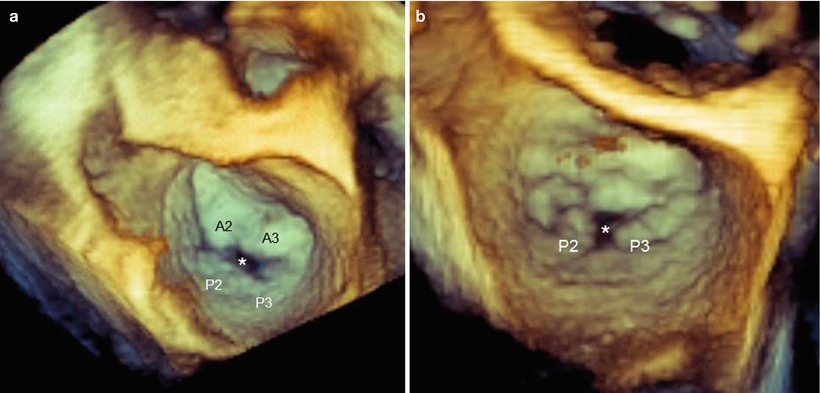


Fig. 3.12
These 3D TEE images from a “surgical” view show functional mitral regurgitation (FMR) with asymmetric tethering. (a) The regurgitant orifice (asterisk) is between P2–P3 and A2–A3. (b) The regurgitant orifice (asterisk) is between P2 and P3
Related posts:


Stay updated, free articles. Join our Telegram channel
Full access? Get Clinical Tree
