Fig. 1.
Overview scheme of steps involved in cryo electron tomographic imaging of cells.
2 Materials
Several pieces of equipment are required for performing cryo electron microscopy on cells. The tools can be divided into the following categories: general accessories for (cryo) electron microscopy and cell culture, cryo specimen preparation tools, a suitable electron microscope, and appropriate hardware and software for image processing. A concise overview of the electron microscopy hardware and tools is depicted in Fig. 2. All items are listed below (between brackets the specific type or brand that is used in our lab):
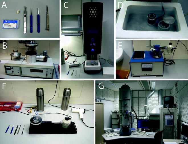
Fig. 2.
Overview of electron microscopy hardware and tools used in cryo electron microscopy. (a) General tools for cryo electron microscopy: EM grids, storage box for cryo grids, tweezers for grabbing cryo storage box, two tweezers for grid handling, and screwdriver. (b) Carbon coater with glow discharging unit. (c) Vitrobot with custom-made cryogenic box with heater. (d) Cryogenic box for vitrobot. Black cylinder is the ethane container with a heating wire around it. On the right the closable container for cryo EM storage box is depicted. (e) Gatan dry pumping station with cryo holder. (f) Cryo holder in station during transfer of grids. Cryo-EM grids are transported in stainless steel flasks in which Greiner tubes, holding the cryo storage boxes, are suspended by a rope. (g) Tecnai F20 with Gatan GIF 2002.
2.1 General Accessories
1.
Carbon coater, for extra carbon coating of grids or for the creation of thin carbon films to be put on grids (Emitech KX950, Emitech, The Netherlands).
2.
Glow discharger, for making carbon layers hydrophilic (Emitech 350, Emitech, The Netherlands).
3.
Tweezers (Ted Pella, USA): (a) Fine tip tweezers, for handling EM grids (Dumont no 5); (b) Bent curved tip or flat tip tweezers, for handling cryo storage boxes during transfer; (c) Long tweezers, for handling cryo storage boxes out of cryo storage tubes.
4.
Screw driver, for opening and closing storage boxes.
5.
Metal grid mesh, for placing grids during glow discharging.
6.
Filter paper, for blotting (Whatman, Kent, UK and Schleicher and Schüll, The Netherlands).
7.
100–300 mesh gold grids with Formvar/carbon film.
8.
Cell culture stove and hood.
9.
Cell growth chemicals.
10.
Upright brightfield light microscope.
2.2 Cryo Specimen Preparation Tools
2.
Vitrification device with humidity and temperature control, for fast freezing of samples (Vitrobot Mark IV, FEI Company, The Netherlands).
3.
Liquid nitrogen, for storing samples and cooling down ethane gas.
4.
Ethane or ethane/propane gas, for vitrification.
5.
Cryo grid storage boxes (Ted Pella, USA).
6.
Cryo storage tubes: Greiner Cellstar 50 ml polypropylene sterile centrifuge tubes (Greiner bio-one, The Netherlands).
7.
Stainless steel 1 L liquid flasks for transfer in liquid nitrogen.
8.
Liquid nitrogen Dewars for storage.
2.3 Electron Microscopy
1.
Medium- or high-voltage transmission electron microscope with field emission gun (FEG). We use a 200 kV FEI Tecnai F20 (FEI company, The Netherlands).
2.
Specimen stage suitable for tilting a frozen hydrated specimen; e.g., a side entry cryo holder (Gatan 626 or 914 cryo holder, Gatan, Germany).
3.
Cryo holder dry pumping station (Gatan 655, Gatan).
4.
Energy filter with digital camera (GIF 2002 with 2 k × 2 k MultiScan CCD camera, Gatan).
2.4 Image Processing Computer and Software
1.
Reasonably powerful computer workstation with >8 Gb RAM and graphics card or small computer cluster (Hewlett-Packard XC cluster).
2.
Tomographic reconstruction and visualization software (IMOD (5); Xplore3D, FEI Company; Amira, Visage Imaging, Germany).
3 Methods
In this section all steps are described to get from cultured mammalian cells to a 3D cryo electron tomography reconstruction. The specific choices for the used materials and methods are described in detail, together with their advantages and disadvantages. Here, the settings are described that we used for visualization of microtubules in mouse embryonic fibroblasts (3, 10). However, to make the description more generic, we summarize the rationale for choosing these settings as an aid to adapt them, depending on the lab-specific available instrumentation, biological subject, and final objective of the electron tomography experiment.
3.1 Cell Support
1.
Grid material. Electron microscopy support grids that are used for cell culture are made of gold. Other metals such as copper and nickel are not suitable for cell cultures, as they are cytotoxic.
2.
Mesh size. Grid mesh sizes between 100 and 300 Mesh are used. The Mesh number should not be too high (>300 Mesh) to keep sufficient transparent space between the grid bars when the specimen is tilted to high angles. On the other hand the metal grid should provide sufficiently sturdy support for the overlaying film. In our hands, with Mesh numbers equal to and lower than 100 the support films tend to break more frequently upon handling and vitrification of the specimen. A 300 Mesh grid seems to be optimal. Alternatively, 300 × 75 Mesh grids having different sizes in different directions can be used in order to increase the overall transparency upon tilting. Take care that the latter grids are placed in the specimen holder such that the 75 Mesh spacing is perpendicular to the rotation axis of the holder.
3.
Support layers. We preferentially use gold grids with a support layer of continuous Formvar, for optimal strength, on both sides coated with evaporated carbon. Formvar support layers are prepared by making a 1% solution in Chloroform or Dicholoromethane, dipping a microscopy glass slide into the solution and, after drying, floating the Formvar layer onto water. Gold grids are placed onto the Formvar layer and picked up again with a glass slide. The Formvar support layer is then carbon coated on both sides. The disadvantage of the use of continuous Formvar/carbon-coated films is that these layers add to the total thickness of the sample. The scattering interactions of the electrons with these layers deteriorate the signal-to-noise ratio of the images and, therefore, the attainable resolution of the 3D reconstruction. To reduce this disadvantage, commercially available holey carbon films, such as Quantifoil, can be used. This type of specimen supports has the advantage that background noise is reduced when these cells are imaged through the holes.
4.
Pretreatment. Just prior to the use of Formvar/carbon-coated grids, glow discharging is applied in 200 mbar air for 1–2 min at 20–40 mA on a carbon coater with additional glow discharge unit. This is performed to increase hydrophilicity of the grid and improve surface contact with the medium during cell culture. Fiducial gold markers of 5, 10, or 15 nm are applied on the grid before cell culture, their size dependent on the desired magnification, to aid image alignment during the tomographic reconstruction. For this, grids are placed for 1 min on a suspension of 5, 10, or 15 nm protein-A gold, blotted with filter paper and dried in air. To improve biocompatibility and cell adhesion, grids are occasionally coated with Collagen by incubating the grid for several hours with a 1:3 dilution of Collagen in ethanol.
3.2 Cell Culture
1.
Cell type. In previous work, we have used primary mouse embryonic fibroblast cells (MEFs) that were purified from mouse embryos. Briefly, the mouse body was cut into pieces and homogenized with collagenase and trypsin. The homogenate was cultured in a 1:1 mixture of Dulbecco’s modified Eagle’s medium and Ham’s F10 medium supplemented with 10% fetal calf serum and penicillin and streptomycin antibiotics in a humidified atmosphere with 5% CO2 at 37°C. Other cell types have also proven to be suitable for cryo electron tomography of whole cells, although mainly mammalian cell types that by nature are thin or have the tendency to spread, like fibroblasts and neurons, can be used. The thickness limit that can be meaningfully imaged by transmission electron microscopy depends on the high voltage used. In most cases, ∼400 nm is regarded as a maximum thickness to image a frozen hydrated specimen with a transmission electron microscope operating at 200 kV. Consequently, it is not possible to perform cryo electron microscopy of whole cells that have an intrinsically cubic or columnar shape, as well as cellular structures that are positioned near the cell nucleus.
2.
Cell growth. EM grids are sterilized before cell growth by 15 min UV radiation. Standard cell culture protocols are used for growth on EM grids. MEF cells are cultured in tissue culture flasks and between 10,000 and 30,000 cells are plated into 5 cm diameter tissue culture dishes, in which EM grids are positioned on the bottom. Cell adhesion is allowed to occur overnight and grids are usable up to several days of culture before vitrification. The amount of cells that are plated should not be higher than 30–50% in order to avoid adjacent or overlapping cells. Before vitrification, the cultured cells should be checked by light microscopy for proper cell attachment to the grids, confluency, and spreading. When little to no cells are attached to the grid, one might want to check the toxicity of the grids (by growing cells in an EM grid free culture dish), increase the confluency or the time for cell culture. Keeping the cells in a 100% humid environment and at 37°C during specimen preparation is important to maintain biological and structural integrity. Therefore, after cell culture, which is performed in a specialized cell culture lab, the culture dishes with the EM grids are transferred to a cell culture stove that is located in the same room as the vitrification device. The EM grid with the cells is transferred onto hot plates that are kept at 37°C or, alternatively, transferred as fast as possible into the vitrification device.
3.3 Vitrification, Storage, and Transfer
1.
Vitrification. For the vitrification process, we use the FEI vitrobot Mark IV. This vitrification device has a temperature and environmentally controlled chamber in which the cells are kept before and during blotting (for a detailed protocol see: (11)). Blotting is performed with filter paper (Whatman no. 4 or paper numbers 595 or 597 from Schleicher und Schüll), using the following parameters: temperature, 37°C; humidity, 100%; blot time, 1–2 s; wait time, 0 s; drain time, 0 s; blot force, 0–25; and blot total, 1.
2.
Custom nitrogen box. On the vitrobot, we use a custom-made “coolant container.” We do not use the standard FEI liquid ethane container for two reasons. In our experience, it is difficult to keep the grids clean from ice contamination (see Note 1) and to keep the liquid ethane at the correct temperature for a prolonged time. Therefore, we use a container that allows heating of the ethane container. In addition, we add a lidded container for a cryo grid storage box in order to prevent contamination (Fig. 2c, d). Additionally, the system has more space for liquid nitrogen and handling. The blotted grid is plunged into liquid ethane (grade PR 3.5 (99.95% pure)) that is cooled by liquid nitrogen and kept in equilibrium with solid ethane (having a matte “milky” appearance). Alternatively a 2:1 mixture of ethane and propane (63.0 mol% propane and 36.98 mol% ethane, custom mixed) can be used. The advantage of the mixture over the pure liquid ethane is that this mixture does not solidify at liquid nitrogen temperatures (12) and no heating of our custom-made container is needed.
3.
Storage. Vitrified grids are stored in cryo boxes (home-made or Ted Pella, Fig. 2a, top left). The small cryo boxes are closed with a cover that is fixed with a screw and stored in liquid nitrogen filled Greiner tubes that are very well resistant to cryo temperatures and can be used for years without noticeable deterioration. Coded strings are attached to these tubes and they are stored in a large liquid nitrogen Dewar for later use. Also Greiner tubes and grid storage boxes are tagged for later grid retrieval.
4.
Transfer. Stored boxes with vitrified grids are transferred from the storage container into a Gatan cryo station, holding a Gatan 626 high tilt cryo holder or Gatan 914 cryo electron tomography holder. The cryo holders are baked out and pumped to low pressure using a dry pumping station to retain maximum insulation. Directly after mounting of a grid into the cryo holder, the grid is subsequently transferred from the cryo station into the electron microscope.
3.4 Microscope and Alignments
3.4.1 The Electron Microscope
1.
We use an FEI Tecnai F20 operated at 200 kV, with an FEG electron source and a 2 k × 2 k CCD camera behind an energy filter. Additionally, the electron microscope is equipped with a goniometer that is suitable for tomography, allowing smooth rotation of the stage to angles up to 70°.
2.
Data collection is best performed on a medium- or high-voltage electron microscope operating at an acceleration voltage of 200 or 300 kV. With these higher electron voltages thicker samples (up to ∼400 nm) can be used. For whole cell imaging with transmission the sample thickness is one of the most stringent limitations that require a sufficiently high acceleration voltage. As an electron source it is advantageous to use an FEG. An FEG has the advantages over other sources such as LaB6 and Tungsten in that the electron beam is more coherent and more suitable for imaging thicker samples at a relatively large defocus, which is necessary for the generation of phase contrast.
3.
Zero loss imaging of the electrons using an energy filter is very advantageous (see Note 2). By using an energy filter in the zero-loss imaging mode (e.g., with an energy slit of 20 eV) the inelastically scattered electrons do not contribute to the final image. Consequently, the signal-to-noise level of images acquired from relatively thick specimen is significantly better compared to unfiltered images. Zero-loss imaging becomes increasingly important at high specimen tilts, since the specimen becomes thicker to the electrons as they traverse it to form a projection image.
4.
Imaging should be performed with a digital image detector, which is indispensible for automated image acquisition. In cryo electron tomography, the number of electrons is in general very low due to the necessary dose fractionation: the acceptable total electron dose has to be distributed over as many images as possible. Consequently, the detector should be highly sensitive. To image the specimen in a large field of view with reasonable resolution, the imaging detector size should be at least 2 k × 2 k pixels in size but preferable larger (4 k × 4 k or even 8 k × 8 k). This allows for either a large field of view or binning of pixels to allow increased effective sensitivity. Most cameras that are currently available for electron microscopes are cooled slow-scan CCD cameras that record light that is generated by the interactions of the electrons with a scintillator positioned on top of the detector. Currently, alternative (direct) electron detectors with superior characteristics in terms of image detection quantum efficiency (DQE) have become commercially available.
3.4.2 Microscope Alignments
Especially for cryo electron tomography, a proper alignment of the electron microscope is vital to assure optimal imaging conditions and a robust data collection performance. Dedicated care has to be taken with some particular alignments that are important for proper tracking of feature movement and focus variation during the acquisition of the tilt series. Under practical circumstances, an optimal microscope alignment is not always achieved by a microscope supervisor. It is useful when the users have the expertise to tweak and optimize these alignments during the tomography session. Therefore, we think it is useful to describe and discuss some important alignments in this chapter. The necessary alignments are in most cases similar for a wide range of transmission electron microscopes and tomographic acquisition software. We will specifically describe the procedures during a tomography session for a Tecnai (F20) microscope.
1.
Eucentric height. After insertion of the cryo holder into the microscope, it must be set to the eucentric height. This means that the height of the holder in the goniometer must match the rotation axis of the goniometer. Many microscope alignments are related to this height as it defines the objective lens focus plane. When the stage is not at eucentric height upon applying specimen tilt, the sample shifts orthogonally to the tilt axis. The eucentric height can be set manually or automatically. For the automatic version to function robustly, it is advisable to first roughly set the height manually. A rough manual alignment of the eucentric height can be performed by centering a recognizable feature at low magnification, tilting the stage and then recentering the feature using the z-height controls. On our Tecnai the automatic eucentric height function is available in the tomography software suite.
2.
Centering of apertures. The condenser and objective apertures have to be aligned properly to the optical axis to prevent beam movements during the tomographic data acquisition. A quick way to check if a condenser aperture is aligned is to center a focused beam and observe whether the beam stays centered during spreading of the intensity. If the area does not stay centered, the condenser aperture is not well aligned. The condenser aperture can be centered by moving the aperture using the two knobs on the aperture mounting. Repeat adjustments until the illuminated area stays centered and only changes size. The objective aperture can be centered by switching the microscope to diffraction mode (where, at the appropriate camera length, the objective aperture is visible as a circular shape) and to move the aperture such that the central diffracted beam is centered within the circular shape.
3.
CCD calibration files. Most of the calibrations and alignments in the tomography software make use of image shift measurements using cross-correlations. Therefore, the quality of the CCD images is an important factor. Unfortunately, in practice, CCD images can suffer from a number of image deteriorating artifacts that have to be corrected for. In most cases, two types of calibration files, often referred to as gain and dark reference images, are needed for the calibration of CCD detectors. Gain references are recorded to correct for the inhomogeneous sensitivity (i.e., gain) of the individual pixels of the detector arising from various sources, e.g., hardware variations of the CCD chip, variations of the scintillator, dust, scratches, and more (13). Dark references are recorded to correct for intensity variations related to the readout and electronics of the data. Using the Gatan CCD detectors on our systems, the dark references are recorded automatically prior to the recording of the illuminated image. Therefore, only the gain references have to be recorded as a separate step. Gain references are recorded for an even (homogeneous) illumination of the CCD detector. One way to verify whether the gain reference files are fine is to record an image at even illumination (preferably at the same image intensity as is anticipated to record the images during the tilt series) and to compute an auto-cross-correlation of the image. The auto-cross-correlation image should show a sharp intensity peak in the center of the image, while the rest should be noisy without any visible pattern. If a pattern of peaks, or bright lines, appears a new gain reference image should be recorded.
4.
 Introduction: Nanoimaging Techniques in Biology
 Secondary Ion Mass Spectrometry Imaging of Biological Membranes at High Spatial Resolution
 Photoswitchable Fluorophores for Single-Molecule Localization Microscopy
 Functional AFM Imaging of Cellular Membranes Using Functionalized Tips
 Correlative Optical and Scanning Probe Microscopies for Mapping Interactions at Membranes
 Nanoimaging Cells Using Soft X-Ray Tomography


Beam tilt pivot points. This alignment makes sure that, upon tilting the beam, the illuminated area on the specimen stays centered. When the pivot point of the beam tilt is not correct (i.e., does not correspond to the specimen plane), this can be observed by the movement of the illuminated area when the illumination is tilted. Beam tilting is used as a way to measure the defocus during autofocusing since the amount of shift is directly related to the amount of defocus. The beam tilt pivot points can be corrected in the direct alignment steps of the microscope. Note that for the alignment and focusing it is important that the sample is at eucentric height. When this is not the case, the illuminated area will shift upon beam tilt. In particular, this can induce problems when the illuminated area is relatively small and is only slightly smaller than the CCD.
Related posts:
Introduction: Nanoimaging Techniques in Biology
Secondary Ion Mass Spectrometry Imaging of Biological Membranes at High Spatial Resolution
Photoswitchable Fluorophores for Single-Molecule Localization Microscopy
Functional AFM Imaging of Cellular Membranes Using Functionalized Tips
Correlative Optical and Scanning Probe Microscopies for Mapping Interactions at Membranes
Nanoimaging Cells Using Soft X-Ray Tomography
Stay updated, free articles. Join our Telegram channel
Full access? Get Clinical Tree
