, Gila Perk2, Natesa G. Pandian3, Hans-Joachim Nesser4 and Itzhak Kronzon2
(1)
Department of Cardiology, Cardiocentro Ticino, Lugano, Switzerland
(2)
Non-Invasive Cardiology, Lenox Hill Hospital, New York, NY, USA
(3)
Tufts University School of Medicine, Boston, MA, USA
(4)
Department of Medicine Elisabethinen, Teaching Hospital, Linz, Austria
Abstract
The atrial septum (AS) is bordered anteriorly by the aortic root and posteriorly by the posterior atrial walls. Because the left atrium is posterior and to the left of the right atrium, the plane of the AS is oriented obliquely and runs from a right posterior to a left anterior position. The best way to visualize the AS by ultrasound is by transesophageal echocardiography (TEE). However, two-dimensional (2D) TEE planes always intersect the septum perpendicular to its surface. Consequently, although this structure is anatomically a fibromuscular membrane dividing the atrial cavities, it is imaged as a linear structure, which may be thicker around the fossa ovalis (FO) and thinner at the level of the floor. Conversely, a unique quality of three-dimensional (3D) TEE is the ability to image internal surfaces of the heart from an en face perspective. Thus, both the left and the right sides of the AS can be visualized en face as they appear in anatomic specimens. The proximity of the transesophageal transducer to the AS (and the nearly perpendicular angle of incidence of the ultrasound beam), the use of transducers at higher frequencies, and, finally, the lack of interference from bones and lung allow the AS to be seen in 3D images of unprecedented quality. This chapter describes the acquisition of real-time (RT) 3D TEE images of the AS, the normal 3D TEE appearance of both left and right surfaces of the AS, the appearance of patent foramen ovalis (PFO) and secundum atrial septal defects (ASDs) on 3D TEE images, and, finally, the use of 3D TEE to guide percutaneous closure procedures for both PFOs and ASDs.
Electronic supplementary material
The online version of this chapter (doi:10.1007/978-1-4471-4745-9_2) contains supplementary material, which is available to authorized users.
The atrial septum (AS) is bordered anteriorly by the aortic root and posteriorly by the posterior atrial walls. Because the left atrium is posterior and to the left of the right atrium, the plane of the AS is oriented obliquely and runs from a right posterior to a left anterior position. The best way to visualize the AS by ultrasound is by transesophageal echocardiography (TEE). However, two-dimensional (2D) TEE planes always intersect the septum perpendicular to its surface. Consequently, although this structure is anatomically a fibromuscular membrane dividing the atrial cavities, it is imaged as a linear structure, which may be thicker around the fossa ovalis (FO) and thinner at the level of the floor. Conversely, a unique quality of three-dimensional (3D) TEE is the ability to image internal surfaces of the heart from an en face perspective. Thus, both the left and the right sides of the AS can be visualized en face as they appear in anatomic specimens. The proximity of the transesophageal transducer to the AS (and the nearly perpendicular angle of incidence of the ultrasound beam), the use of transducers at higher frequencies, and, finally, the lack of interference from bones and lung allow the AS to be seen in 3D images of unprecedented quality. This chapter describes the acquisition of real-time (RT) 3D TEE images of the AS, the normal 3D TEE appearance of both left and right surfaces of the AS, the appearance of patent foramen ovalis (PFO) and secundum atrial septal defects (ASDs) on 3D TEE images, and, finally, the use of 3D TEE to guide percutaneous closure procedures for both PFOs and ASDs.
2.1 How to Acquire 3D TEE Images of the Atrial Septum
One of the easiest ways to obtain an en face view of the AS and surrounding atrial walls is from the 2D TEE bicaval view, using a zoom acquisition modality. The dimension of this sector should be as large as possible in x and z directions, in order to include the entire AS, while the y direction should include only the left and right sides of the septum. This specific setting allows the AS to be acquired in high resolution, excluding most of the surrounding right-sided structures. Because the area captured in this manner is extensive, the frame rate drops to as low as 5 Hz/s, resulting in an image that appears to move less smoothly than the 2D image. Once the pyramidal data set has been acquired, a 90° up-down angulation shows the entire left aspect of the AS in an en face perspective. To obtain an anatomically correct orientation, the image should be rotated in such a way that the mitral valve is at the lower left corner of the image (Fig. 2.1).
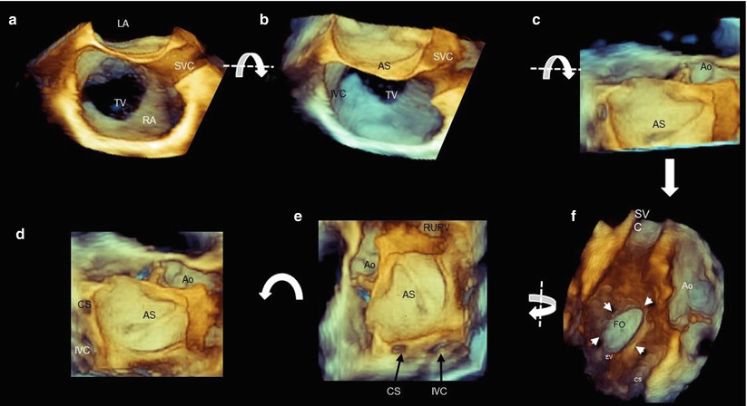
Fig. 2.1
A composite panel showing steps to obtain an image of the left side of the atrial septum (AS). (a) Three-dimensional (3D) image similar to a bicaval two-dimensional (2D) transesophageal echocardiography (TEE) plane. (b, c) Up-down angulation of the image around the x-axis (curved arrow); the anterior half of the AS is seen in an en face view. (d) Uncropped image in the direction of the arrow, showing the entire left side of the AS. (e) A counterclockwise rotation of 90° (curved arrow) around the z-axis showing the AS in anatomically correct orientation (right upper pulmonary vein positioned at 12–1 o’clock position). (f) A 180° rotation around the y-axis (curved arrow) shows the right side of the AS. Arrows point at the borders of the fossa ovalis (FO) (see also Video 2.1). AO aorta, CS coronary sinus, IVC inferior vena cava, LA left atrium, MV mitral valve, RA right atrium, RUPV right upper pulmonary vein, SVC superior vena cava, TV tricuspid valve
2.2 Normal Anatomy of the Atrial Septum
2.2.1 Left Side
The left side of the AS is relatively featureless when viewed from the left atrial perspective. A small irregularity called the atrial pouch often can be seen superiorly and anteriorly to the fossa ovalis (FO). This structure (resembling a kangaroo pouch) is due to a partial fusion of the septum primum with the septum secundum, which remains attached only at the caudal border of the overlap zone. The resulting pocket opens into the left atrial cavity (Figs. 2.2 and 2.3). This left atrial pouch is a potential site of stasis with thromboembolic complications.
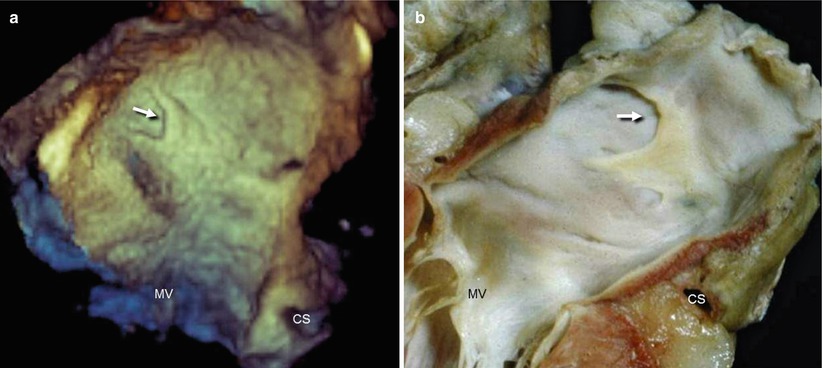
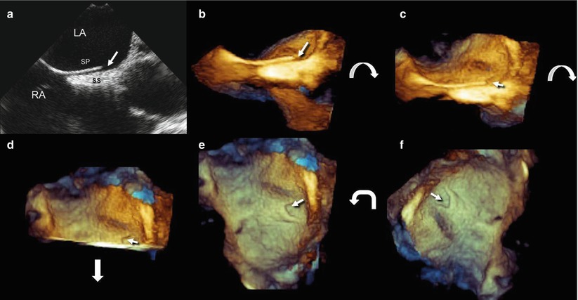
Fig. 2.2
(a) Left side of AS showing the left atrial pouch (arrow). Characteristically, the atrial pouch has a curved appearance with an anterior concavity (arrow). (b) The corresponding anatomic specimen. CS coronary sinus, MV mitral valve (Courtesy of Edgardo Bonacina; Niguarda Hospital, Milan, Italy)
Fig. 2.3
A composite panel showing steps to visualize the left atrial pouch (arrow) by 2D and 3D TEE. (a) Bicaval 2D TEE view. (b) A 3D TEE image of the same view as in panel a. (c, d) Up-down rotation on the x-axis (curved arrow), showing the anterior half of the AS en face. The arrow points to the curved left atrial pouch. (e) Uncropped image in the direction of the arrow in panel d, showing the entire left side of the AS. (f) Counterclockwise 90° rotation (curved arrow) on the z-axis, showing the AS in anatomically correct orientation. LA left atrium, RA right atrium, SP septum primum, SS septum secundum
From the left atrial side, the area of the FO may appear to have a lack of tissue, owing to dropout artifacts. These dropouts often have irregular and indistinct margins and can be distinguished from true defects, which typically have more distinct and regular borders. The dropout artifacts are probably due to the fineness of the flap closing the FO. Another possible reason is that the AS may be concave rather than completely flat. When the FO is positioned obliquely or parallel to the ultrasound beam, there are more scattering than specular echoes, thus creating a dropout artifact (Fig. 2.4).
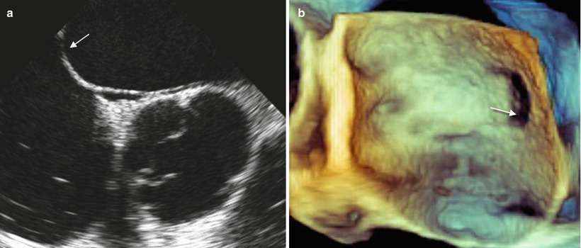
Fig. 2.4
Dropout artifacts of the fossa ovalis. (a) The region of the FO indicated by the arrow is parallel to the ultrasound beam. At this point, there are more scattered than specular echoes, so their reflection is weak, resulting in a dropout. (b) In the 3D image, the dropout is more pronounced than in the 2D images, giving the perception of a defect (arrow)
A slight increase in gain may reduce (but often not eliminate) these dropouts (Fig. 2.5). Anatomic landmarks from this perspective are the coronary sinus and the right upper pulmonary vein. Occasionally, a large aortic sinus may abut the left atrial wall (Fig. 2.6).
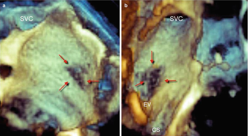
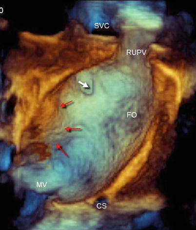
Fig. 2.5
Dropout artifacts of the fossa ovalis from the left (a) and right (b) atrial perspectives (red arrows). A slight overgain may avoid dropout artifacts (i.e., perceiving the background depth) but produce more static noises. CS coronary sinus, EV eustachian valve, SVC superior vena cava
Fig. 2.6
Left side of atrial septum in anatomically correct orientation, showing anatomic landmarks. The white arrow points to the left atrial pouch. Red arrows point to the aortic sinus abutting the left atrial wall. CS coronary sinus, FO fossa ovalis, MV mitral valve, RUPV right upper pulmonary vein, SVC superior vena cava
2.2.2 Right Side
A 180° rotation from the left side shows the right side of the AS characterized by the FO and its surrounding rim (Video 2.1). The FO is completely overlapped by its valve, a flap of tissue that is continuous with the left atrial wall. The rim often appears as raised muscle that surrounds the crater-like depression of the FO (Fig. 2.7). The size, shape, and location of the FO may differ significantly among individuals. This variability may affect the distance of its margins from structures around the fossa and is important during transseptal punctures (Fig. 2.7). Anatomic landmarks from this view are the eustachian valve and the coronary sinus ostium (Fig. 2.8). Because the aortic root is partially between the two atrial cavities, a large aortic sinus may abut the right atrial wall. Other surrounding structures, such as the inferior and superior vena cavae, can be visualized simply with a slight up-down and down-up angulation, respectively (Fig. 2.9). The FO is better defined when the surrounding rims are thicker than usual, as can be seen in the presence of a lipomatous septum (Fig. 2.10).
Get Clinical Tree app for offline access
Fig. 2.7
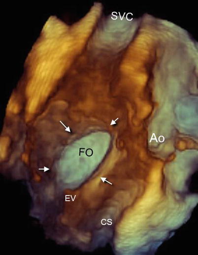
Right side of atrial septum showing the fossa ovalis (FO) and the surrounding rim (arrows). Note other anatomic landmarks such as the eustachian valve (EV) and coronary sinus (CS). Ao aorta, SVC superior vena cava
Fig. 2.8
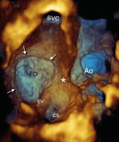
Right side of atrial septum showing a large fossa ovalis (FO). Arrows mark the margins of the FO. The asterisk marks the aortic sinus protruding against the atrial wall. Ao aorta, CS coronary sinus, EV eustachian valve, SVC superior vena cava
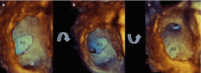
Fig. 2.9
(a) Right side of atrial septum showing the fossa ovalis (FO), eustachian valve (EV), and coronary sinus (CS). A slight up-down angulation (b) reveals the inferior vena cava (IVC), and a slight down-up angulation (c) reveals the superior vena cava (SVC)
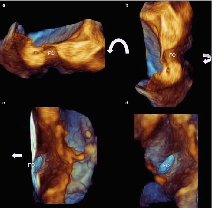
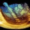
Fig. 2.10
(a) Three-dimensional TEE imaging of a small fossa ovalis with a thick rim due to a lipomatous septum. The section is obtained by 2D TEE in the bicaval plane, with the y direction set so that it includes only the atrial septum. (b) Counterclockwise rotation (curved arrow) on the z-axis allows the anatomically correct orientation to be achieved. (c, d


Related posts:


Stay updated, free articles. Join our Telegram channel
Full access? Get Clinical Tree
