, Andreas Koschan2 , Chung-Hao Chen3 and Mongi Abidi2
(1)
Seagate Technology PLC, Bloomington, MN, USA
(2)
Imaging, Robotics, and Intelligent Systems Laboratory, Department of Electrical Engineering and Computer Science, The University of Tennessee, Knoxville, TN, USA
(3)
Department of Electrical and Computer Engineering, Old Dominion University, Norfolk, VA, USA
Abstract
Surveillance and inspection have an important role in security and industry applications and are often carried out with line-scan cameras. The advantages of line-scan cameras include hyper-resolution (larger than 50 Megapixels), continuous image generation, and low cost, to mention a few. However, due to the physical separation of line CCD sensors for the red (R), green (G), and blue (B) color channels, the color images acquired by multi-line CCD cameras intrinsically exhibit a color misalignment defect, such that the edges of objects in the scene are separated by a certain number of pixels in the R, G, B color planes in the scan direction. This defect, if not corrected properly, can severely degrade the quality of multi-line CCD images and hence impairs the functionality of the cameras. Current techniques for correcting such color misalignments are typically not fully automated, which is undesirable in applications such as inspection and surveillance that depend on fast unmanned responses. This chapter introduces an algorithm to automatically correct the color misalignments in multi-line CCD images for rotational scans as well as for translational scans. Results are presented for two different configurations of multi-line CCD imaging systems: (a) a close-range multi-line CCD imaging system for inspection applications and (b) a long-range imaging system for surveillance applications. Experimental results show that the two imaging systems are able to acquire hyper-resolution images and the color misalignment correction algorithm can automatically and accurately correct those images for their respective applications.
Keywords
Color correctionColor misalignmentHyper-resolution color imageMulti-line CCD cameraLine-scan cameraImage acquisitionImaging system1 Introduction
Remote sensing, surveillance and inspectional scanning have an important role in security and industry applications and usually require acquiring hyper-resolution (larger than 50 Megapixels) images of a constant stream of materials or landscapes with relative motion. Such applications are often carried out with line-scan cameras because of their advantages, including: (i) hyper-resolution (at least thousands of pixels in one dimension and the size in the other dimension is limited only by the capacity of storage device); (ii) continuous image generation (video stream compared to discrete video frames generated from a frame-based camera); (iii) low cost (compared to still image cameras with a 2-D imaging sensor array that can achieve the same resolution).
1.1 Line-Scan Imaging Sensor and Applications
A line-scan camera is an imaging device generally containing a line-scan imaging sensor chip, supporting electronics and an optical system that includes one or multiple lenses and a focusing mechanism. Gupta et al. introduced a simplified camera model for line-scan imaging sensors [1]. Unlike video cameras and regular still image cameras, a line-scan camera has a single row (1-D) of pixel sensors, instead of a 2-D array of them.
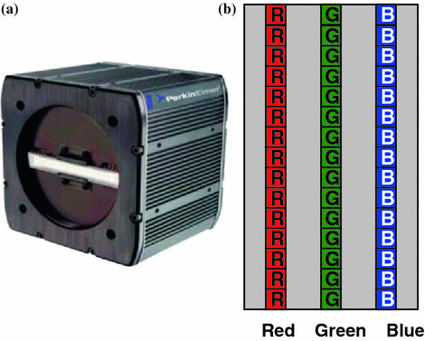

Fig. 1
a A line-scan CCD camera with three line sensors for color image capture. b Illustration of RGB line-scan sensors
Figure 1a shows a picture of a line-scan camera without the lens and focusing mechanism. Figure 1b illustrates the configuration of the RGB-multi-line CCD sensor on that camera which is capable of capturing color images.
There are two major technologies for solid-state imaging sensors, i.e., CCD (Charge-Coupled Devices) sensors and CMOS (Complementary Metal Oxide Semiconductor) sensors. The charge-coupled device was invented in 1969 at AT&T Bell Laboratories by Willard Boyle and George E. Smith [2–5]. CCDs have been in existence for over four decades and the technology has matured to the point where very large, consistent devices can now be manufactured. Compared to CCD technology, the CMOS imaging sensor technology is not as mature, but it is set to develop rapidly and offer a number of advantages over CCDs in terms of low power, low cost and monolithic integration. Nowadays active pixel CMOS imaging sensors have been optimized for optical sensing and can rival CCD counterparts in most aspects [6, 7].
One image frame captured by a line-scan camera contains only one row of pixels. In order to capture a 2-D image with such a camera, the 1-D frames are continuously fed to a computer that joins them to each other. Due to the much shorter time of transferring 1-D frames instead of 2-D frames out of the imaging chip, line-scan cameras are capable of capturing sharp hyper-resolution images of objects passing in front of the camera at high speeds. Therefore, this kind of camera is commonly used in sports events to acquire photo finishes, i.e. to determine the winner when multiple competitors cross the finishing line at nearly the same time. Line-scan CCD cameras have significant advantages and play important roles in many industrial, scientific and military applications. The areas in which line-scan cameras have important applications include, but are not limited to, remote sensing, surveillance, high speed document/film scanning, industrial quality control inspection, surface inspection, racing sports, etc. Common applications of line-scan cameras in the area of remote sensing and surveillance include satellite and aerial imaging, and their applications in the area of industrial quality control inspection include printing inspection, produce and food inspection, textile inspection, etc.
Line-scan technology is capable of capturing data extremely fast and at very high image resolutions. Under such conditions the acquired image data can quickly exceed 100 MB in a matter of seconds. Data coming from the line-scan camera has a frequency at which the camera scans a line, waits, and repeats. The one-dimensional line data from the line-scan camera is commonly collected by image acquisition electronics, e.g., a frame grabber card in a computer, and then processed by the computer to create a 2-D image. The raw 2-D image is then processed by image-processing techniques in order to meet application objectives. Figure 2 illustrates the data path of a line-scan imaging system.
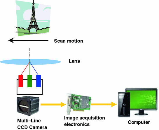

Fig. 2
The data path of a line-scan imaging system
Numerous novel applications of line-scan imaging systems have been reported in the literature. For example, Wilson reported an on-line surface inspection system designed to characterize the rotary screen-print process of applying up to 20 separate colors to a continuous textile web for the textile industry [8]. Reulke et al. developed a mapping method of combining high resolution images acquired by a line CCD camera with depth data acquired by a laser scanner. Application areas are city modeling, computer vision and documentation of cultural heritage [9–12]. Huang et al. developed a rotating-line-camera imaging system for stereo viewing and stereo reconstruction [13, 14]. Maresch et al. used three partially inclined and vertical linear CCD arrays and developed a vehicle-based 3-line CCD camera system for 3D city modeling [15]. Yoshioka et al. developed a vehicle lane change aid system (LCAS) with multi-line CCD sensors [16]. Bowden et al. designed a line-scanned micro Raman spectrometer using a cooled CCD imaging detector to obtain sequences of Raman spectra [17]. Ricny et al. developed an autonomous optoelectronic method of measuring the flying objects track velocity vector using two-line CCD sensors [18]. Kroll et al. developed a system using an 8-bit CCD line scanner for automatic determination of the brightness of star-like objects on a photographic plate [19]. Demircan et al. used a wide angle CCD line camera to measure the bi-directional reflectance distribution function of natural surfaces [20]. Kipman et al. developed a method of measuring gloss mottle and micro-gloss using a line-scan CCD camera [21]. Rosen et al. used a line-scan CCD image sensor for on-line measurement of red blood cell velocity and microvascular diameter [22].
1.2 Color Misalignment Defect of Multi-Line CCD Images and its Correction
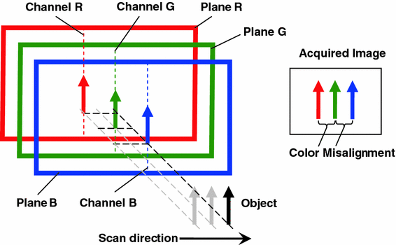
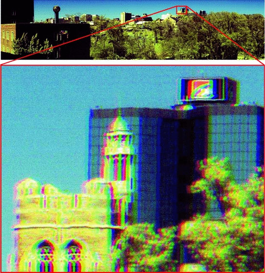
Hyper-resolution is one of the major advantages of line CCD images. However, due to the physical configuration and characteristics of multi-line CCD sensors, raw output images acquired by multi-line CCD cameras typically exhibit some defects, and may not be usable for desired application purposes. For example, because of the physical separation of line CCD sensors for the red (R), green (G), and blue (B) color channel, the color images acquired by multi-line CCD cameras intrinsically exhibit a color misalignment defect, such that the edges of objects in the scene are separated by a certain number of pixels in the R, G, B color planes in the scan direction. This defect, if not corrected properly, can severely degrade the quality of multi-line CCD images and hence impair the functionality of multi-line CCD cameras. Figure 3 illustrates the creation of color misalignment, and Fig. 4 shows a raw multi-line CCD image with such a defect. This misalignment can be considered a major problem in hyper-resolution multi-line CCD scans and is also called pixel lag [23] or video delay [24]. There are two commonly used methods for correcting color misalignment in multi-line CCD imaging:
The above methods have significant drawbacks and/or limitations. Both methods are not fully automated. Synchronizing the line acquisition rate to the object’s motion is not an easy task. Furthermore, this method puts undesirable constraints on imaging parameters, e.g., line acquisition rate, exposure time, aspect ratio of acquired images, etc. The imaging parameters that synchronize the line acquisition rate to the scan motion speed may create images with undesirable or even unacceptable brightness and aspect ratios. Setting the video delay parameter can avoid putting undesirable constraints on imaging parameters; however, similar to the synchronization method, setting the correct video delay parameter before and/or when imaging is taking place is not an easy task. It is usually done by the user via visual inspection, which is subjective and not accurate, and the acquired images may still exhibit small color misalignment.
(1)
Synchronize the CCD line acquisition rate to the object’s moving speed and/or the camera’s scan motion [23].
(2)
Set the video delay parameter of the multi-line CCD camera to compensate the target motion for the physical separation of color sensors. When the camera reconstructs the color image, the adjacent color planes are shifted by a certain number of lines that was specified by the video delay parameter [24].

Fig. 3
Illustration of the creation of color misalignment

Fig. 4
Color misalignment in a multi-line CCD image
Since the current techniques for correcting color misalignments are not fully automated, and may put adverse constraints on imaging parameters, they are undesirable in applications such as inspection and surveillance that depend on fast unmanned responses. In order to greatly expand the applications of multi-line-scan cameras, it is important to develop a technique that can fully-automatically correct color misalignments in multi-line CCD images and does not put constraints on imaging parameters.
This chapter introduces an algorithm to automatically correct color misalignments in multi-line CCD images for rotational scans as well as for translational scans. Results are presented for two different configurations of multi-line CCD imaging systems: (a) a close-range multi-line CCD imaging system for inspection applications and (b) a long-range multi-line CCD imaging system for surveillance applications. This chapter is organized as follows: Section 2 presents the setup of two of our multi-line CCD imaging systems. Section 3 introduces a fully-automated color misalignment correction algorithm. Experimental results are presented in Sects. 4 and 5 concludes this chapter.
2 Multi-Line CCD Imaging Systems
We used a multi-line CCD camera to develop two hyper-resolution imaging systems, i.e., a close-range line-scan imaging system for inspection applications and a long-range system for surveillance applications. In the following, the configurations of the two imaging systems are presented.
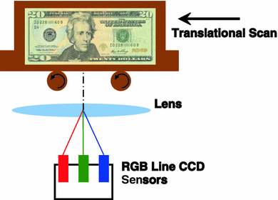
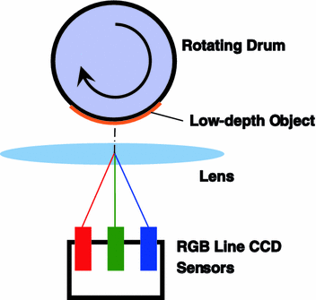

Fig. 5
A close-range imaging system with translational scan scheme

Fig. 6
A close-range imaging system with translational scan schem
2.1 Translational Scan and Rotational Scan
In order to create 2-D images, a relative scan motion between the line-scan camera and the scene is necessary during the imaging process. There are two kinds of scan schemes—translational scan and rotational scan. Figures 5 and 6 illustrate two translational scan schemes. Translational scan is more suitable for close-range imaging; since the distance between the object to be imaged and the lens is constant in translational scan, the focus does not need to be adjusted and the image remains focused during the imaging process. For close range imaging, due to narrow depth of field, the object is usually a flat surface or an object with small depth. In the scan scheme illustrated in Fig. 5, the object is located on a platform which can undergo a translational scan motion across the field of view of the line-scan camera, and the scan speed can be adjusted by the user to change the aspect ratio of acquired images. In the scan scheme illustrated in Fig. 6, a rotating drum is placed in front of the camera lens to provide the scan motion. A flat or low-depth object is attached to the drum surface. Although the drum rotates, the scan motion seen by the line-scan camera is translational.
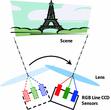
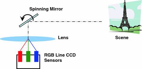

Fig. 7
A long-range imaging system with a rotating camera to provide scan motion

Fig. 8
A long-range imaging system with a rotating camera to provide scan motion
Figures 7 and 8 illustrate two rotational scan schemes. Rotational scan is more suitable for long-range imaging, since it enables the line-scan camera to scan a wide scene with the camera being fixed to one location. There are two ways to provide a rotational scan motion for a long-range imaging system:
The spinning mirror design has a significant advantage over the rotating camera design, because the mechanical system for spinning a long, narrow light-weight mirror is smaller, lighter and less expensive than that for rotating the entire imaging system; therefore, the system is more mobile and more suitable for outdoor applications. The disadvantage of the spinning mirror design is that it is more susceptible to wind when used for outdoor image acquisitions because of the mirror’s light weight and relatively large area. Wind can cause the mirror to vibrate slightly, and slight vibrations of the spinning mirror can severely impair the quality of acquired images because of the hyper-resolution nature of these images. Therefore, in order to minimize the effect of wind and mechanical vibration, the rotation mechanism and the fixture for attaching the mirror to the mechanism need to be carefully designed. In addition, the wind effect can be significantly reduced by placing a glass windshield in front of the spinning mirror.
(1)
The camera rotates to sweep across the scene. Figure 7 shows the schematic of a long-range imaging system with a rotating camera to provide scan motion.
(2)
A spinning mirror is placed in front of the camera lens and reflects the moving scene into camera. Figure 8 shows the schematic of a long-range imaging system with a spinning mirror to provide scan motion.
2.2 Close-Range Multi-Line CCD Imaging System
We developed a close-range multi-line CCD imaging system incorporating a PerkinElmer multi-line-scan camera for inspection applications. A picture of this system is shown in Fig. 9. This imaging system consists of a YD5060 tri-linear CCD color camera, a bellows, a short focal-length (90 mm) lens, DC diffusive illumination lights, and scanning mechanism. These system components are mounted on a metal plate platform for stabilization and easy transportation. The DC diffusive lights provide intense, constant and uniform illumination over the object to ensure that the image formed on sensor lines has sufficient brightness.
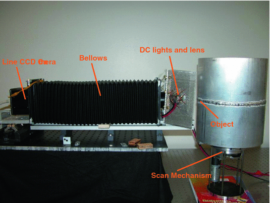

Fig. 9
Example of a close-range imaging system
Stay updated, free articles. Join our Telegram channel

Full access? Get Clinical Tree


