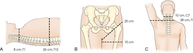
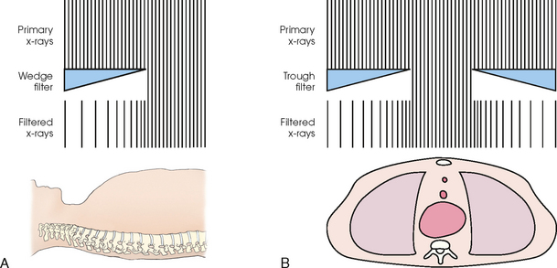
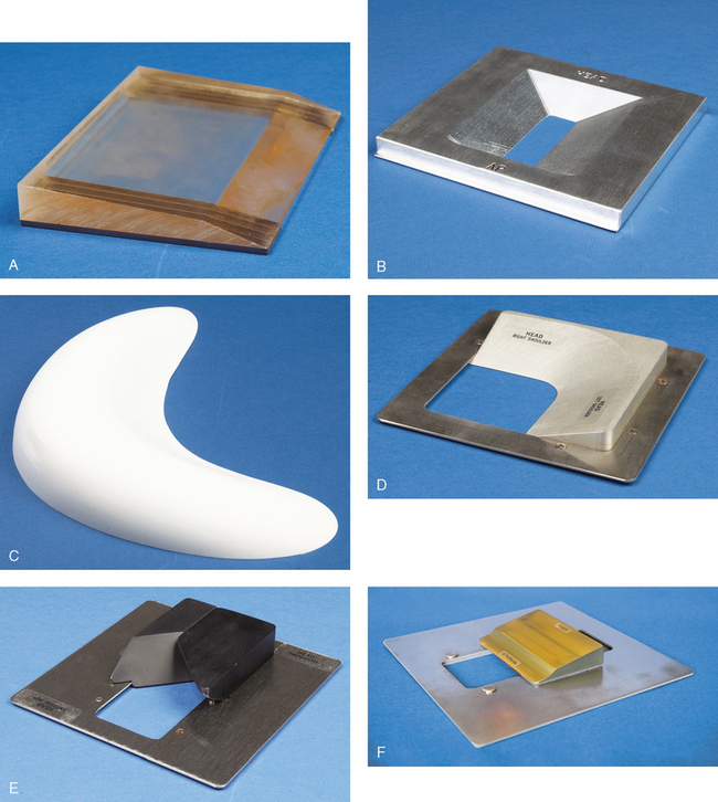
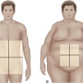
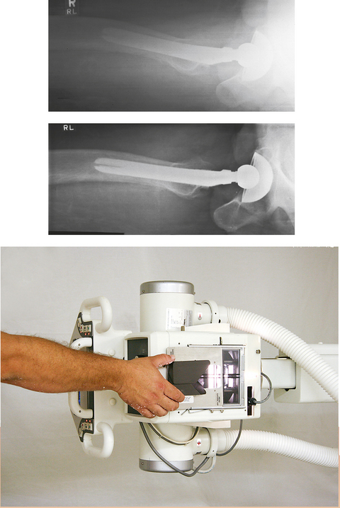
2 Examples of x-ray projections that have to show significantly varied tissue density include the anteroposterior (AP) projection of the thoracic spine, the axiolateral projection (Danelius-Miller method) of the hip, and the lateral cervicothoracic region (swimmer’s technique) (Fig. 2-1). Exposure of these structures with a uniformly intense x-ray beam results in the production of an image with areas of underexposed or overexposed anatomy. To compensate for these variations in tissue density, specially designed attenuating devices called compensating filters can be placed between the radiographic tube and the image receptor (IR). The resulting attenuated beam more appropriately exposes the various tissue densities of the anatomy and reveals more anatomic detail. Equally important, the filter reduces the entrance skin exposure and the dose to some of the organs in the body (Fig. 2-2). The technique of compensatory filtration was first applied in 1905 by Pfahler, 1 not long after x-rays were first discovered. Pfahler used wet shoe leather as the filter by wrapping it around a patient’s arm. Compensating filters of one type or another have been in use since that time. Some of the most common filters in use today are shown in Fig. 2-3. These filters can be used with screen-film and digital imaging systems to improve the image quality of various anatomic areas. With most digital systems, filters are necessary to obtain a diagnostic image of a body part with extreme differences in density. In addition, radiation exposure to the patient is reduced through elimination of extra exposures needed to show all of the anatomy and through the beam-hardening effect of the attenuating filter. The increasing thickness of the filter over the thinner body part also acts to reduce exposure. The appropriate use of radiographic compensating filters is an important addition to the radiographer’s skill set. The radiographer determines whether or not to use a filter based on an assessment of the patient and determines the type and exact position of the filter. This determination is made while positioning the patient. Radiographic projections of the lateral hip and the lateral C7-T1 cervicothoracic region in most instances require a filter to show all the anatomy on one image. Projections such as the AP shoulder and AP thoracic spine may not need a filter on hyposthenic patients; however, on hypersthenic patients and patients who are “barrel-chested” or obese, a filter is necessary. Pediatric patients seldom require a filter except when posteroanterior (PA) and lateral projections of the full spine are done in cases of spinal curvatures such as scoliosis. Compensating filters for full-spine radiography not only allow the entire spine to be imaged with one exposure, but they also significantly reduce the radiation exposure to the young patients who require these images.1–3
COMPENSATING FILTERS
Introduction
COMPENSATING FILTERS