(1)
where I, A are multi-channel images, L is a single-channel image (same size as I and A), and
 is the component-wise product of the pixel values.
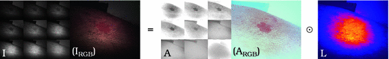
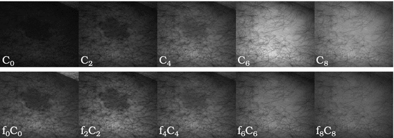
Fig. 1.
Example of separating a multispectral image I into albedo A and illumination L (false-colors) using our method.  and
and  are projections of their respective multispectral images, I and A, onto RGB space. Here and in all following figures, a heat color-map is used to visualize the illumination L (Color figure online).
and are projections of their respective multispectral images, I and A, onto RGB space. Here and in all following figures, a heat color-map is used to visualize the illumination L (Color figure online).Multispectral imaging is a powerful tool for tissue classification, due to its improved spectral resolution compared to conventional RGB imaging, with the latter only approximating the subjective color perception of the human eye. This improved spectral resolution allows for better tissue discrimination, however this is hampered by the presence of large illumination changed across the image. As lesion classification methods [3] rely on many features that can be observed on a lesion, such as color and fine structures, they are quite sensitive to illumination changes. Our motivation is to exploit the additional information of multispectral imaging, in order to compensate for such illumination changes, while preserving both morphological and colorimetric (spectral) features of the lesions.
In applications that recover the albedo or just compensate for illumination for detail enhancement [1, 10], it is common practice to acquire multiple images while keeping the viewpoint fixed and varying the illumination. The assumption is made that the albedo remains the same while the illumination changes. In our work we also acquire multiple images under a fixed viewpoint, however we do not vary the illumination but the spectral range for each image channel. We assume that it is the spatial distribution of the illumination that remains constant and that the albedo varies.
We introduce a two step approach based on low-rank decomposition of the multispectral image I in order to approximate a per-pixel illumination map L which enables the recovery of the diffuse albedo A. We evaluate the method on multispectral images of synthetic lesions on volunteers and of real lesions of patients.
2 Related Work
When considering Eq. (1), the image I cannot be separated into A and L without additional information.
Photometric stereo methods [10] acquire multiple images, while keeping the viewpoint fixed. In each image, the scene is illuminated from a different calibrated direction. Here, both the the surface geometry and albedo are estimated together. More recently [1], the requirement for calibrated illumination has been relaxed, only assuming the light sources to be sufficiently distant. Although multispectral imaging can be adapted to such multi-light acquisitions [9] (which considerably increases acquisition times), our focus is on illumination compensation from a single multispectral image.
Similar data as in [1] (fixed viewport multi-light images) is used by image enhancement methods [6, 14] which, rather than removing the illumination altogether, focus on minimizing its influence, while preserving fine features, that would otherwise be lost without illumination cues. Fattal et al. [6] propose an image decomposition method for multi-light image sequences that removes large illumination artefacts (like shadows) while enhancing small surface details due to shading. Such methods have a simpler model than photometric stereo of how light interacts with the scene as they only focus on image enhancement.
These methods [1, 6, 10, 14] all exploit variations in illumination in order to recover the albedo. This is not unlike our method, we however make the reverse assumption, that the albedo varies and that the illumination stays the same.
Influences of illumination can also be modeled in single images when enough assumptions can be made about the scene. Shi et al. [11] propose an adaptive linear function that estimates the background of historical documents, compensating for uneven shading due to paper geometry and non-uniform illumination. For robust face recognition, Chen et al. [2] propose an illumination normalization approach based on a Discrete Cosine Transform in the logarithmic domain. Although not exactly modeling illumination, the methods focuses on preserving application relevant features while removing most image illumination.
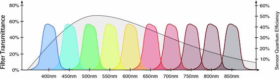
Fig. 2.
Example transmission spectra of band-pass filters (colored functions), and example spectral sensitivity of image sensor (larger gray function) (Color figure online).
Vogel et al. [13] present a radiometrically calibrated multispectral imaging system to assess tissue vasculature. The authors model both the distribution of the illumination across the image and the geometry of the subject. The former is mostly corrected for by the radiometric calibration of the camera and the calibrated illumination, leaving only the influence of the geometry. Assumptions are made about the geometry of the object and a simple curvature model is fitted to the data in order to compensate for the remaining shading. This method has the most similar input data and hardware to our own, however, most of the influences of illumination are corrected through a calibrated and controlled acquisition environment. Unlike Vogel et al. [13] we make no assumptions about either the distribution of light intensity or the geometry of the scene.
3 Methods
Our method exploits the increased spectral resolution of multispectral images in order to distinguish between the most important spectra that influence image formation: illumination, background and foreground. As this method was initially developed for dermatology, the background is the skin and the foreground is the lesion we are investigating. The method can also be used on multiple foreground and/or background spectra as long as certain criteria are met (see Sect. 3.2).
3.1 Multispectral Image Formation
For simplicity we will focus only on the spectral information and how that relates to pixel intensity values without considering complete imaging optics.
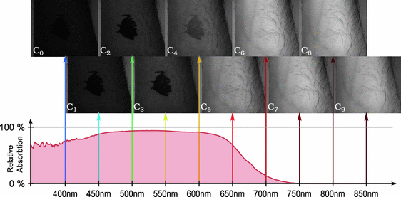
Fig. 3.
Example multispectral image of a forearm marked with a red dye that has a similar absorption spectrum as an erythemous lesion (Fig. 1). Above 700 nm the dye is no longer distinguishable from the skin, just as its relative absorption spectrum would indicate (relative to skin) (Color figure online).
The basic layout of a multispectral camera is analogous to that of most RGB camera: lens, filters and gray-scale sensor. Where a RGB camera has a color filter array (CFA) consisting of tiny red, green and blue filters mounted directly on the sensor, a multispectral camera can have different designs in order to support a considerably larger number of filters. Although we will only focus on filter-wheel cameras1, our method can be applied on images acquired with any type multispectral camera.
Sensors used in multispectral cameras have a wide spectral sensitivity (Fig. 2), however they cannot distinguish the wavelength of the photons they detect. The transmission spectra (Fig. 2) of the camera filters act as windowing functions, letting only a certain part of the spectrum through. This is how both RGB and multispectral cameras are able to distinguish between different parts of spectrum of the incoming light: they use the filters to select what wavelengths reach the sensor. Therefore the intensity value  for a pixel p of channel i is:
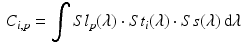
with  the spectrum of the light entering the camera,
  the transmission spectrum of the
  channel, Ss the sensitivity spectrum of the sensor and wavelength
  . Considering that we store the spectra as discrete vectors, Eq. (2) can also be written as:
for a pixel p of channel i is:(2)
the spectrum of the light entering the camera, the transmission spectrum of the channel, Ss the sensitivity spectrum of the sensor and wavelength . Considering that we store the spectra as discrete vectors, Eq. (2) can also be written as:(3)
Fig. 4.
Selected channels of the multispectral image (detail view of lesion from Fig. 1):  before (top row) and
  after (bottom row) global illumination correction/normalization.
before (top row) and after (bottom row) global illumination correction/normalization.3.2 Modeling Illumination
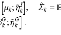
Illumination compensation can be viewed as reversing image formation in order to separate the multispectral diffuse reflectance A from the illumination L. Handling a multispectral image  consisting of k channels (
 ), can be simplified by linearizing all channels. Therefore a channel
  can be described by:
with the global illumination term  and the local illumination term
  and a channel and pixel dependant albedo
  . The reshaped I can be modeled as the component-wise multiplication of A with the outer product between L and f:
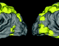 Stable Overlapping Replicator Dynamics for Multimodal Brain Subnetwork Identification
 Transfer Segmentation
 Method to Discover Genetically Driven Image Biomarkers
 Segmentation and Registration Through the Duality of Congealing and Maximum Likelihood Estimate
 Tumor Growth Prediction with Multiplicative Growth and Image-Derived Motion
 Frames for Heart Fiber Reconstruction


consisting of k channels (), can be simplified by linearizing all channels. Therefore a channel can be described by:(4)
and the local illumination term and a channel and pixel dependant albedo . The reshaped I can be modeled as the component-wise multiplication of A with the outer product between L and f:Related posts:
Stable Overlapping Replicator Dynamics for Multimodal Brain Subnetwork Identification
Transfer Segmentation
Method to Discover Genetically Driven Image Biomarkers
Stay updated, free articles. Join our Telegram channel
Full access? Get Clinical Tree
