
Computer-Assisted Image-Guided Fluoroscopy (Virtual Fluoroscopy)
The field of spine surgery has witnessed many advances in recent years. Numerous technological developments, particularly in the areas of imaging, intraoperative navigation, and spinal instrumentation, have expanded the range of disease processes that may be treated.
To surgically manage patients with spine disease, it is necessary to have reliable preoperative and intraoperative imaging. Magnetic resonance imaging (MRI) and computed tomography (CT) have revolutionized the spine surgeon’s ability to diagnose and treat spinal pathology. However, technical limitations and cost considerations have hindered the widespread availability of these imaging modalities in the operating room. Nevertheless, accurate visualization of anatomy is essential in the surgical suite, and it has become more important as the complexity of spine surgery has increased. Variations in musculoskeletal anatomy, either as a result of congenital anomaly, degenerative disease, or trauma, can adversely affect a surgical procedure and lead to a suboptimal result or a serious complication.
Fluoroscopy is an imaging technique that is familiar to spinal surgeons. It is routinely employed to improve intraoperative visualization of bony anatomy. By replacing direct visualization with radiographic visualization, it has enabled a reduction in surgical exposure, duration, and blood loss. Its use has facilitated a variety of complex spinal procedures, including pedicle screw insertion, interbody cage placement, odontoid screw insertion, and atlantoaxial transarticular screw fixation. This imaging technology has also been vital in the development of percutaneous spinal procedures, such as vertebroplasty.
Despite the advantages of intraoperative fluoroscopy, the technique has its limitations. The C-arm can be cumbersome to maneuver around a sterile operative field. Because only a single projection can be visualized at one time (without a second fluoroscope), it is necessary to reposition the C-arm during procedures that require multiple planes of visualization. There is also the issue of radiation exposure, which can be considerable for spinal surgeons.1
A desire to improve intraoperative visualization led to the development of image-guided surgery systems for spinal surgery. The first such systems were CT based and were an extension of systems used for cranial neurosurgery.2 Further development of image-guided technology has resulted in a second class of systems that differ in terms of the type of imaging that is used to provide the image guidance. These systems are based upon fluoroscopy itself.3–6
A CT-based image-guided system relies upon the acquisition of a preoperative computerized tomogram with a specific protocol. The data from this image is transferred to the image-guidance system prior to surgery. Intraoperatively, patient registration is performed by identifying anatomic landmarks, or fiducial points, that correspond to analogous points in the image data set. The advantage of a CT-based system is that CT provides excellent anatomic detail for common spine regions of interest, such as the pedicle, and it allows for true three-dimensional guidance. The disadvantages of a CT-based system are several.5 First, there is the need to obtain a preoperative CT scan with a specific protocol. This adds time and cost to the process (typically, even if a preoperative CT scan has been obtained for diagnostic purposes, it does not follow the parameters necessary for image-guided system use). Second, the CT scan is obtained in the supine position on the scanner gantry, whereas most spine procedures that use image guidance are performed in the prone position on an operating table. This changes the relationships between the individual vertebrae (rigid bodies) that exist in the CT image (image space) and those same vertebrae in the patient (surgical space). Thus, each vertebra must be individually registered, adding time to a multilevel procedure. As well, intersegmental trajectories (e.g., for C1–2 transarticular screw fixation) are not accurately depicted by the image-guided computer. Third, the CT-based system’s images cannot be refreshed intraoperatively (without an intraoperative CT scanner). If intersegmental relationships change intraoperatively, as with distraction of an interspace or reduction of a deformity, this cannot be depicted by the image-guided computer display. Finally, registration of fiducial landmarks, which can be tedious and time-consuming, is required during surgery when using a CT-based system.
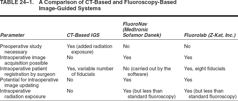
A fluoroscopy-based system employs commonly available C-arms augmented with accessories that allow accurate measurement of the relationship between the C-arm and the patient.3–6 The system takes patient and C-arm position data for a given projection and relates that data to the fluoroscopic image from that projection. After calibrating the system with positional and fluoroscopic data from one or more projections, the computer generates a mathematical model of the fluoroscopic image that enables the superimposition of tracked surgical instruments onto the saved fluoroscopic images. Thus the real-time position of these instruments is displayed as it relates to one or more previously acquired fluoroscopic images, even in multiple planes, simultaneously. We term this process virtual fluoroscopy.3,4,6 The advantages of virtual fluoroscopy are that no special preoperative study is required, intraoperative patient registration is automated (for some systems3,4,6), the images may be updated as necessary in the operating room, and an imaging modality is employed that many surgeons use routinely in the course of spine procedures. Table 24–1 provides a comparison of the CT-based and fluoroscopy-based image-guided systems.
Fluoroscopy-based systems are available that are either integrated with conventional image-guided surgery systems (FluoroNav Virtual Fluoroscopy System and Stealth-Station, Medtronic Surgical Navigation Systems, Louisville, CO) or exist as stand-alone devices (Stealth-Station Ion Fluoroscopic Navigation System, Medtronic Surgical Navigation Systems, Broomfield, CO; Z-Kat, Inc., Miami, FL).
The use of virtual fluoroscopy has not been limited to spine procedures. It has also been used to assist in the navigation of the bony anatomy of the parasellar region for transsphenoidal hypophysectomies.7 In addition, it has been used extensively for orthopedic procedures such as intramedullary nail or screw insertion, acetabular fracture fixation, iliosacral screw insertion, and hip pinning. A variant of the technology involves the roadmapping utility, which is used during angiography procedures. In this application, the image of a vessel of interest is stored as a digital template and the real-time fluoroscopic image, which includes a catheter or guidewire, is superimposed on the previously stored vessel of interest during device manipulation.
 Description of Systems
A typical virtual fluoroscopy system (Fig. 24–1) consists of an image-guidance computer system, a commercially available fluoroscopic C-arm, a calibration device that attaches to the C-arm, and specially modified surgical instruments that are capable of being tracked by the image-guidance system. The system may be operated by the surgeon through a sterile interface, or it may be operated by an assistant.
The operation of a virtual fluoroscopy system may be divided into four basic steps: (1) fluoroscopic image acquisition, (2) C-arm and patient position measurement, (3) merging of the fluoroscopic images with their unique C-arm and patient positions to create a mathematical model (mapping) of the image formation process, and (4) measurement of the position of surgical instruments in the operative field so that their likeness may be superimposed upon the virtual fluoroscopic images.4,6
In the first step, conventional fluoroscopic images are automatically transferred to the computer for image processing. In the second step, information about the relative position of the C-arm and the patient is acquired. This can be done by cameras that detect the location of light emitting diodes or passive reflectors that have been attached to the C-arm and the patient. The markers that are attached to the patient are in the form of a dynamic reference array (DRA), which rigidly attaches to the portion of the patient’s anatomy that is to be imaged. Other means of position sensing (electromagnetic, sonic, mechanical, etc.) can also be used.
In the third step, the computer calibrates the acquired fluoroscopic image by taking into account the positional data acquired in the second step. Based upon the inputted images, a mathematical mapping function is generated that allows a virtual fluoroscopic image to be produced for a unique combination of C-arm and patient position. The calibration process compensates for factors such as gravity-dependent changes in the C-arm image center, the effect of external electromagnetic fields generated by electrical equipment in the operating room, and the effect of changes in the C-arm’s position with respect to the earth’s magnetic field. Because of these compensation factors, which are unique to every C-arm position, it is necessary that every acquired image be independently calibrated.6 This can be accomplished quickly and efficiently through the use of a computerized algorithm.
In the fourth step, the computer determines the position of one or more trackable surgical instruments using a position-measuring camera and then superimposes an image of the instrument(s) in the virtual fluoroscopic display. Dedicated tracked awls, probes, taps, and screwdrivers are available, and any rigid surgical instrument may be tracked with the assistance of a universal tool array. The system is capable of correctly displaying the position of the surgical instrument(s) in any of the previously acquired fluoroscopic images, in multiple planes, simultaneously. The system also allows the actual projection of a surgical instrument (in one color) and the simultaneous projection of the linear extension of that instrument’s proposed trajectory (in a second color) (Fig. 24–2).
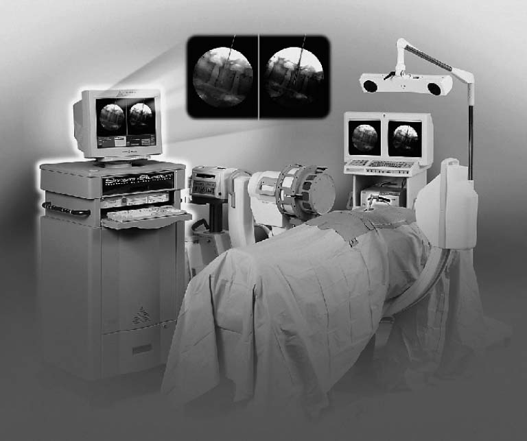
FIGURE 24–1. The FluoroNav (Medtronic SNT, Louisville, CO) virtual fluoroscopy system is shown, consisting of an image-guidance computer system and camera array, a calibration target that is attached to a standard C-arm fluoroscope, and various tracked tools. (From Foley KT, Simon DA, Rampersaud YR. Virtual fluoroscopy: computer-assisted fluoroscopic navigation. Spine 2001;26:347–351. With permission.)
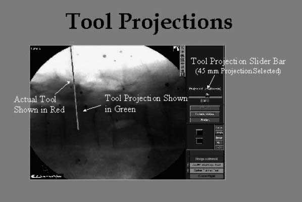
FIGURE 24–2. A lateral virtual fluoroscopic view of the lumbar spine is shown. The pedicle probe (dark line) has been positioned at the pedicle entry point. Its trajectory (light line) has been virtually extended 45 mm into the pedicle and vertebral body.
System accuracy
The accuracy of various virtual fluoroscopy systems has been tested experimentally. Foley et al performed a cadaver study comparing live and virtual fluoroscopic images in which a tracked probe was inserted into pedicles from L1 to S1.3
Related posts:
 Intraoperative Image Update by Interface with Ultrasound
Stay updated, free articles. Join our Telegram channel

Full access? Get Clinical Tree


