Chapter 21 Dental radiography
Dose reduction and radiation protection
As long ago as 1994 in the UK, the National Radiological Protection Board (NRPB) issued guidelines stating that there was no justification for the routine use of lead rubber aprons.1 In practice, the artefacts caused by incorrect placement of lead rubber aprons during orthopantomography (OPT) were considered to be a common cause of repeat radiographs, thereby doubling the radiation dose received by the patient. At this stage the NRPB also concluded that dental radiography posed no risk to women at any stage during pregnancy; however, as the use of lead rubber does not actually increase the dose to patients, it could be suggested that its use for any intraoral or cephalometry technique may be of ‘psychological’ benefit to the patient. This may be especially appropriate in the case of the patient who is aware of the risks associated with ionising radiation but who is not reassured by the radiographer’s explanation that there is no likelihood of danger when undergoing dental radiographic examinations. Since the 1994 NRPB document there have been key documents issued regarding guidelines and regulations on the use of radiation for medical exposure, each referring less specifically to the use of lead rubber for dental examinations but emphasising the responsibility of the radiographer to reduce the radiation dose wherever possible.2–4 In view of this, and the previous comments on the ‘psychological’ benefits to the patient, it may be more appropriate to offer all patients lead rubber aprons for intraoral and cephalometric examinations.
Terminology associated with dental radiography
Dental techniques require an understanding of some terms that are not encountered in radiography of the rest of the body; these are outlined in Table 21.1.
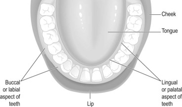
| Buccal/labial (Fig. 21.1) | The (outer) aspect of the teeth that lies between the teeth and the cheeks or lips |
| Lingual/palatal (Fig. 21.1) | The (inner) aspect of the teeth that lies between the teeth and the tongue |
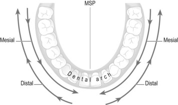
| Distal (Fig. 21.2) | The direction of the dental arch towards the molars, posteriorly and outwards away from the MSP. Used to describe beam shift, tube shift or angulation |
| Mesial (Fig. 21.2) | The direction of the dental arch towards the incisors, anteriorly and inwards towards the MSP. Used to describe beam shift, tube shift or angulation and is in the opposite direction to distal movement |
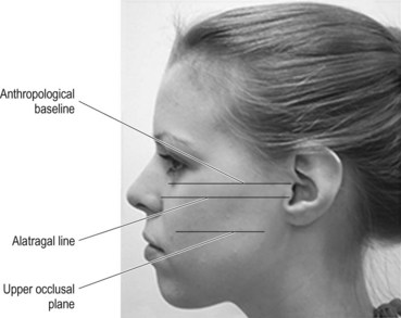
| Alatragal line (Fig. 21.3) | An imaginary line from the tragus of the ear to the middle of the ala of the nose (the flare of soft tissue around the nostril) |
| Occlusal plane (upper) (Fig. 21.3) | The line of the biting surfaces of the upper teeth. When the mouth is closed this is deemed to be the occlusal plane rather than the upper occlusal plane. The line lies parallel to the anthropological baseline and the alatragal line. It lies approximately 4 cm below the alatragal line |
| Occlusal plane (lower) | With the mouth open, this line lies parallel to, and approximately 2 cm below the line which lies between the tragus of the ear and the outer canthus of the mouth. Because all radiography of the teeth should be undertaken with the mouth closed around an IR holder or occlusal film, this plane is not actually used in this text and is therefore not illustrated |
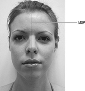
| Medial sagittal plane (MSP) (Fig. 21.4) | Plane running vertically down the middle of the face, separating the left and right sides |
Techniques used in dental radiography
Intraoral techniques
Bitewings: Demonstrate the crowns and interproximal surfaces of the teeth.
Periapicals: Demonstrate the whole tooth.
Extraoral techniques
Orthopantomography (OPT or OPG)/dental panoramic tomography (DPT): Demonstrates the whole mouth, including dentition, mandible, maxillary sinuses and temporomandibular (TMJ) joints. This technique is covered in Chapter 22.
Lateral cephalometry: Mainly used to assess the extent of malocclusions and facial deformities prior to and post surgery. This technique is covered in Chapter 22.
Recording and displaying the image
Digital dental units use small image receptors (IRs) which are connected to the digital unit (Fig. 21.5) and these are similar in size to films used in dental radiography.
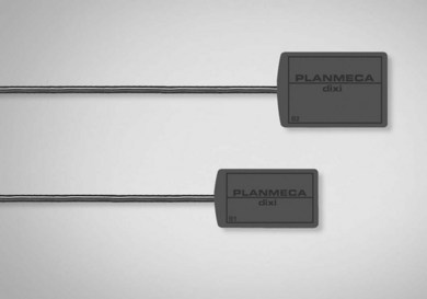
Figure 21.5 Digital dental image receptors.
Reproduced with permission from Xograph Imaging Systems.
Receptor orientation
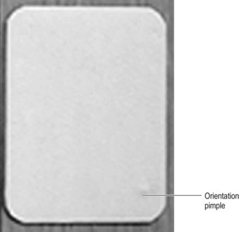
A consistent method must be used to orientate the film in the mouth, since it is impossible to tell whether teeth are from the left or right side, from the mandible or the maxilla. The most familiar method was to use the orientation ‘pimple’ when using film; this is a tiny but palpable raised lump on the tube side of the film (Fig. 21.7). The pimple is always positioned towards the crowns of the teeth in periapical and occlusal examinations. For bitewings the pimple is usually orientated towards the roots of the upper teeth. Digital IRs are always used with the lead leaving the edge of the receptor, which is outside the mouth, and identification must be annotated onto the resulting image at the postprocessing stage.
Displaying film images
Films are usually mounted with patient and tooth/projection identification in clear holders or stapled to clear film or translucent mounting medium. The ‘pimple’ must face outwards, towards the viewing radiographer. Left and right teeth are also clearly indicated. Before the widespread use of OPT for whole-mouth examinations, whole-mouth periapical images were displayed in the format of the mouth itself.5
Intraoral techniques: bitewings
These demonstrate the crowns, interproximal surfaces and gingival margins of the premolars and molars. Bitewing film is available, which is a small dental film with a centralised flap of paper on the tube side of the film. Film/IR size is equivalent to size 1. The patient’s teeth bite on the flap in order to immobilise and maintain position (Fig. 21.8A). Bitewing holders are also available: these are a disposable device into which the film is inserted; a plastic flap at 90° to the film is placed between the patient’s teeth.
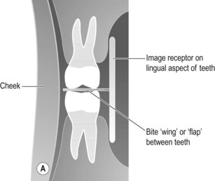
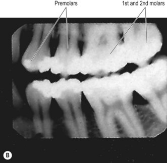
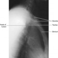
Figure 21.8 (A) Position of IR for bitewings and relationship to teeth; (B) bitewing image.
(B) Reproduced with permission from Whaites E. Essentials of dental radiography and radiology. 3rd ed. Edinburgh: Churchill Livingstone; 2002.
Positioning
• The patient is seated with their neck leaning on a support
• A bitewing film or bitewing holder is placed with its tube side in contact with the lingual surface of the teeth under examination and the flap between the occlusal surfaces of the teeth
• The patient closes their teeth over the flap
• The median sagittal plane (MSP) is vertical and the upper occlusal plane horizontal
Criteria for assessing image quality
• Crowns of the teeth and alveolar crests are demonstrated
• No evidence of elongation or foreshortening of teeth
• No overlap of adjacent teeth
• Slight separation of occlusal surfaces of teeth
• Sharp image demonstrating enamel in contrast with pulp cavity and the alveolar crests
| Common errors | Possible reasons |
|---|---|
| Foreshortening of the teeth | Poor beam selection or the IR has slipped away from the lingual surface of the teeth |
| Overlap of the crowns at their interproximal surfaces | Beam not at 90° in the mesiodistal direction |
Intraoral techniques: periapicals
Periapical examinations are generally used to demonstrate individual or small groups of teeth. Before the introduction of OPT/OPG or DPT the whole of the mouth was examined in this way, with images mounted to represent the layout of the dentition.5 OPT examination has almost exclusively superseded this approach.
More specifically, the most significant problems can be identified as:
1 The teeth are surrounded at their neck and root by the bones of the maxilla or mandible, which are themselves surrounded by the gum. This reduces the proportion of the tooth that can be placed in close contact with the IR. When added to the arched construction of the hard palate, positioning of the IR parallel to the tooth becomes problematic. The teeth themselves are arranged in a variation of angles in the mouth, the incisors being at a much greater angle than the molars.
2 The size of the patient’s mouth will affect the possibility of positioning the IR, since a narrow dental arch may not accommodate the IR.
3 Overlapping teeth when the dentition is overcrowded will mean that it is impossible to provide images of some teeth without some superimposition.
Two techniques are available for periapicals: bisecting angle and paralleling
Stay updated, free articles. Join our Telegram channel

Full access? Get Clinical Tree


