and  (cloud parameter and shadow parameter, in the order given), increasing the algorithm flexibility. The equation that describes this operation is:
 is the average value of image pixels,
  is the sum of the average value pixels and the standard deviation value of the image and
  is the subtraction of the average value by the standard deviation pixels.
The region labeled as  represents a shadow region, labeled as
  means region not affected by atmospheric interference, while regions labeled as
  represents thin clouds, and dense cloud are labeled as
  . For images with multiple bands these labels are assigned if and only if the rule is valid for all bands.
represents a shadow region, labeled as means region not affected by atmospheric interference, while regions labeled as represents thin clouds, and dense cloud are labeled as . For images with multiple bands these labels are assigned if and only if the rule is valid for all bands.To complete this process, it is applied a morphological opening operation that aims to remove very small objects that can cause mistakes in following steps.
2.2 Image Decomposition
The method proposed by Vese and Osher [18] decomposes an image into two sub-images, each representing the components of structure or texture, thus, a better image redefinition can be made. On the structured part, should be applied the technique of inpainting based on DCT, whilst into texture portions and heterogeneous areas is suitable to use texture synthesis.
The generalized model is defined as:

where  is the input image,
  is the structure image and
  is the texture image. So, given these sub-images one can reconstruct the original image. However, in practice it is observed that the original image can be only approximately reconstructed. The goal of the method is to have a structure image
  that preserves all strong edges with smoothed internal regions, and an image
  that contains all the texture and noise information.
(2)
is the input image, is the structure image and is the texture image. So, given these sub-images one can reconstruct the original image. However, in practice it is observed that the original image can be only approximately reconstructed. The goal of the method is to have a structure image that preserves all strong edges with smoothed internal regions, and an image that contains all the texture and noise information.The method used to construct the structured image  is based on the assumption that
  is a
is a  function and in attempt to minimize this function in the space of all Bounded Variation functions (BV). Functions in BV space are functions whose total variation are limited by some constant value less than infinity. Minimizing
  in BV space ensures resulting in a stable image and without infinite values. It should be noted, however, that this space allows for functions which have very large derivatives (although non-infinite), thereby ensuring that strong edges are preserved.
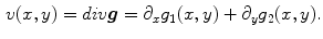
is based on the assumption that is a function and in attempt to minimize this function in the space of all Bounded Variation functions (BV). Functions in BV space are functions whose total variation are limited by some constant value less than infinity. Minimizing in BV space ensures resulting in a stable image and without infinite values. It should be noted, however, that this space allows for functions which have very large derivatives (although non-infinite), thereby ensuring that strong edges are preserved.Taking in mind the intuition described above, the minimization problem should logically have two terms. One of them will be the fidelity, responsible for maintaining the difference between  and
and  small. This term ensure that data of the input image are kept on result. The other one imply a smoothing over
  , although not necessarily in all
  components. The minimization is computed as [14]:
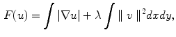
![$$\begin{aligned} F(u) = \left[ (\int {|\nabla u|}) + (\lambda \int {|f - u|^2})\right] dxdy, \end{aligned}$$](/wp-content/uploads/2016/03/A320009_1_En_15_Chapter_Equ3.gif)
with  and
and  representing the gradient operator. The second term is the data term and the first one is a regularization term to ensure a relatively smooth image.
  is a tuning parameter. As can be seen, this seeks find the optimal
  and ignores the
  image. The reason is that, in Vese and Osher [18], the authors had considered the
  image to be noise, and therefore to be discarded.
and small. This term ensure that data of the input image are kept on result. The other one imply a smoothing over , although not necessarily in all components. The minimization is computed as [14]:(3)
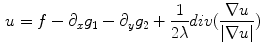
and representing the gradient operator. The second term is the data term and the first one is a regularization term to ensure a relatively smooth image. is a tuning parameter. As can be seen, this seeks find the optimal and ignores the image. The reason is that, in Vese and Osher [18], the authors had considered the image to be noise, and therefore to be discarded.There is an unique result to this optimization problem, and methods exist for finding the solution. Noting that  it is possible to easily modify the above equation to incorporate
  :
:
(still  ). Which yields the Euler-Lagrange equation
 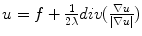 . Making the right manipulation
 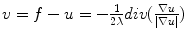 . At this point it is useful to break
  into its
  and
and  components respectively. It will be denoted as
  and
and  , where:
This allows us to write  as:
as:  where
where  . It can be seen that
  , so that
 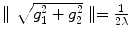 .
.
it is possible to easily modify the above equation to incorporate :(4)
). Which yields the Euler-Lagrange equation . Making the right manipulation . At this point it is useful to break into its and components respectively. It will be denoted as and , where:(5)
as: where . It can be seen that , so that .This allows us to rewrite  as:
as:
And leads to the final minimization problem ( ):
):
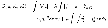
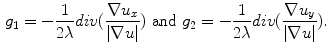
Solving the minimization problem (Eq. 7) yields the Euler-Lagrange equations:
![$$\begin{aligned} \mu \frac{g_1}{\sqrt{g_1^2 + g_2^2}}&= 2\lambda [\frac{\partial }{\partial _x}(u-f) + \partial _{xx}^2 g_1 + \partial _{xy}^2 g_2] \end{aligned}$$](/wp-content/uploads/2016/03/A320009_1_En_15_Chapter_Equ9.gif)
![$$\begin{aligned} \mu \frac{g_2}{\sqrt{g_1^2 + g_2^2}}&= 2\lambda [\frac{\partial }{\partial _y}(u-f) + \partial _{xy}^2 g_1 + \partial _{yy}^2 g_2] \end{aligned}$$](/wp-content/uploads/2016/03/A320009_1_En_15_Chapter_Equ10.gif)
as:(6)
):(7)
(8)
(9)
(10)
2.3 Inpainting by Smoothing Based on Multidimensional DCT
This method was proposed by Garcia [7], and so as in Bertalmio et al. [1], is based on the information propagation by smoothing. The specificity of this approach is related to the use of the Discrete Cosine Transform (DCT) to simplify and to solve linear systems, to an efficient smoothing.
2.3.1 Smoothing by Penalized Least Squares Regression
In statistics and data analysis, smoothing is used to reduce experimental noise or information and keeping the most important marks of the data set. Considering the following model for the one-dimensional noisy signal  from the Eq. 11.

where  represents a Gaussian noise with zero mean and unknown variance, and
  is the so-called smoothing, i.e., has continuous derivatives up to some order (usually
  2) throughout the domain. The smoothing of
  depends on the best estimate of
  and this operation is usually performed by a parametric or nonparametric regression.
from the Eq. 11.(11)
represents a Gaussian noise with zero mean and unknown variance, and is the so-called smoothing, i.e., has continuous derivatives up to some order (usually 2) throughout the domain. The smoothing of depends on the best estimate of and this operation is usually performed by a parametric or nonparametric regression.A classic approach to smooth is the Penalized Least Squares Regression. This technique minimizes a criterion that balances the data fidelity, measured by the Residual Sum-of-Squares ( ) and by a penalty term (
 ), which reflects the robustness of the smoothed data. Another simple and straightforward approach to express the robustness is by using a Second-order Divided Difference (
 ), which produces an one-dimensional array of data.
) and by a penalty term (), which reflects the robustness of the smoothed data. Another simple and straightforward approach to express the robustness is by using a Second-order Divided Difference (), which produces an one-dimensional array of data.Now, using  and the
  , the minimization of
  results in a linear system, expressed in Eq. 12, which allows the smoothed data determination.
where  is the identity matrix
  ,
,  is a positive real scalar that controls the grade of smoothing, so that, as it increases, the degree of smoothing of
  increases too; and
  represents the transpose of
  . Its important to note that
  is a penta-diagonal symmetric matrix, and the last equation can be solved numerically in a computationally efficient way.
and the , the minimization of results in a linear system, expressed in Eq. 12, which allows the smoothed data determination.(12)
is the identity matrix , is a positive real scalar that controls the grade of smoothing, so that, as it increases, the degree of smoothing of increases too; and represents the transpose of . Its important to note that is a penta-diagonal symmetric matrix, and the last equation can be solved numerically in a computationally efficient way.2.3.2 Smoothing Equally Spaced Data
Equation 12 can be solved using the left division matrix applied to sparse matrices [7]. Solving this linear system, however, can be a lot of time expensive for a large amount of data. But, this algorithm can be simplified and accelerated, since the data are evenly spaced, in images where pixels are equally spaced, resulting in the following equation for multidimensional data:
where DCT and IDCT
 e-Slide in the e-Laboratory of Cytology: Where are We?
 Heritage and 3D Models
 of the Prognostic Relevance of Longitudinal Brain Atrophy in Post-traumatic Diffuse Axonal Injury Using Graph-Based MRI Segmentation Techniques
 Sampling and Reconstruction for Sparse Magnetic Resonance Imaging
 Image Processing
 Image Segmentation by Weighted Image Gradient Norm Terms Based on Local Histogram and Active Contours


(13)
Related posts:
of the Prognostic Relevance of Longitudinal Brain Atrophy in Post-traumatic Diffuse Axonal Injury Using Graph-Based MRI Segmentation Techniques
Stay updated, free articles. Join our Telegram channel
Full access? Get Clinical Tree
