, Foster D. Lasley2, Indra J. Das2, Marc S. Mendonca2 and Joseph R. Dynlacht2
(1)
Department of Radiation Oncology, CHRISTUS St. Patrick Regional Cancer Center, Lake Charles, LA, USA
(2)
Department of Radiation Oncology, Indiana University School of Medicine, Indianapolis, IN, USA
Definitions
D = Dose
d = Depth (sometimes called z)
D max = Maximum dose to a point, defined as = 100 %
d max = The depth of D max (sometimes called z max )
SSD = Source-to-surface (skin) distance
SAD = Source-to-axis distance
PDD = Percent depth dose
TAR = Tissue-air ratio
TPR = Tissue-phantom ratio
TMR = Tissue-maximum ratio
SAR = Scatter-air ratio
MU = Monitor Unit
K = Calibration factor (cGy/MU)
OF, S cp = Output Factor
ISF = Inverse Square Factor
S c = Collimator scatter
S p = Phantom scatter
WF = Wedge factor
TF = Tray factor
How Does a Dose Calculation Work?
What is a Monitor Unit (MU)?
MU for linacs is analogous to “beam on time” for Co-60 and orthovoltage units.
MU is measured by an ion chamber inside a linear accelerator (linac) head.
Linacs are calibrated so that 1 MU = 1 cGy under specific reference conditions, variable among institutions.
Measured in water phantom.
SSD setup (SSD = 100) vs SAD setup (SSD < 100).
10 × 10 cm 2 field size, almost always.
Reference Depth varies (dmax, 5, 10 cm).
As we change our prescription depth, field size, shape etc., we will need more or less beam to deliver the same dose.
The purpose of dose calculation is to figure out how much MU!
SSD and SAD Setups
SSD setup uses a constant distance between the source and the surface/skin.
SSD can be changed as needed (100, 110 cm, etc.).
Increasing the depth of the prescription point will increase its distance from the source.
PDD is used for SSD dose calculations.
SAD setup uses a constant distance between the source and isocenter.
This allows for rotation around a fixed isocenter, and is therefore much more common for modern-era radiation therapy.
SAD is a fixed value for any given machine (80 cm for Co-60, 100 cm for linac).
TAR/TMR/TPR (collectively known as TXR) are used for SAD dose calculations.
Hand Calcs (SSD Setup)

(8.1)

(8.2)
What are all of these factors?
K = Output Factor (cGy per MU):
K = 1.0 if linac was calibrated to dmax at 100 SSD.
Otherwise it may be different, and may also vary with field size.
ISF = Inverse square factor:

(8.3)
SSD ref = SSD under reference conditions.
PDD, S c , S p , WF and TF are each discussed below.
Percent Depth Dose (PDD)
PDD is defined as a percentage of D max , measured at different depths within a water phantom at a fixed SSD (usually 100 cm).
Due to the fixed SSD, the source-to-detector distance will increase with increasing depth.
PDD changes with depth due to buildup, attenuation and distance (inverse-square factor).
The shape of the PDD curve depends on beam energy:
Higher energy beams have a larger buildup region and therefore have a lower PDD at low depth (<d max ).
Higher energy beams are more penetrating and therefore have a higher PDD at high depth (>d max ).
The surface dose, PDD(d = 0), decreases significantly with beam energy. This is responsible for skin sparing and the build-up effect at superficial depths.
PDD (10 × 10 cm 2 field, d = 10) increases with beam energy and is used to measure beam quality in TG–51.
For a detailed discussion of beam quality see Chapt. 7.
Extended SSD
Does extending the SSD make you hot or cold?
It depends! What is the question being asked? (Fig. 8.1)
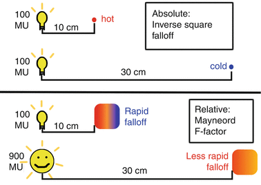
Fig. 8.1
Extended SSD effects. When SSD is extended, dose decreases according to the Inverse Square law (an absolute decrease). However, dose will no longer fall off as rapidly with depth (a relative increase).
Radiation is like heat; if you put wings directly on the grill they will cook much faster than if you put them on the top rack.
Extended SSD decreases the inverse square factor (ISF), so it takes more beam-on time (MU) to deliver the same dose.
The wings on direct heat are more likely to burn the skin before cooking the center, while wings on the top rack will cook more evenly.
Dose homogeneity improves with extended SSD.
10 cm depth is very deep relative to 20 cm SSD, but not so deep relative to 200 cm SSD.
Therefore PDD increases with SSD.
The magnitude of this increase can be calculated by the Mayneord F–Factor (named after the British physicist who first described it).
Mayneord F-Factor
Mayneord F–factor Mnemonic:
“old and deep” (old SSD + d) * “new and shallow” (new SSD + dmax), over the opposite, and then squared.

(8.4)
The F-factor (the bracket term in Eq. 8.4) is usually a small adjustment. Under normal circumstances it is just a few percent.
If you do a F-factor calculation and end up with 1.10 or 1.20, you probably made a mistake. Double-check your numbers.
SC and SP: Scatter Factors and Field Size
Increasing the field size increases output (cGy/MU) – why?
Primary dose does not change.
Scatter dose increases with field size.
Scatter dose is zero for an infinitely narrow beam, because anything that scatters exits the beam.
A broader beam allows more of the scatter to remain inside the field.
Scatter factors are divided into two components:
Collimator scatter (S c ) comes from the linac head (mostly the primary collimator, not the collimator jaws) (Fig. 8.2).
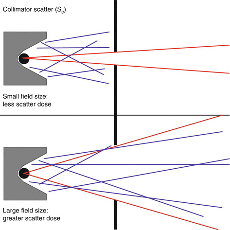
Fig. 8.2
Collimator scatter. Scatter increases with field size, as depicted above.

(8.5)
Phantom scatter (Sp) comes from the phantom.
Measuring dose in a phantom gives a combination of collimator and phantom scatter. Therefore the collimator scatter must be divided out:

(8.6)

(8.7)
When blocks (MLCs) are used, the field size for S
Stay updated, free articles. Join our Telegram channel

Full access? Get Clinical Tree


