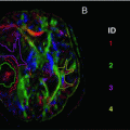
Fig. 10.1
Overview of different steps in the VBA pipeline of DTI data
Summary Points
VBA assumes that the spatial location of voxels is equivalent between subjects,
Natural variation in anatomy and pathology causes an inherent mismatch between individual images that can be corrected by registration to a template,
The VBA pipeline contains three main steps: spatial normalization (or image registration), smoothing, and statistical analysis.
Image Registration
Introduction
One of the main assumptions of VBA is that the same voxels in different images are aligned to each other. Only in this case, can DTI measures, such as FA or MD, be compared between the same voxels of different subjects. Note that the process of spatially matching different images is frequently described using different terms, such as normalization, warping, aligning, registration, coregistration, etc. But in the end, although these terms may differ slightly in their technical definition, essentially they refer to the same concept.
A simplified example of the registration concept is shown in Fig. 10.2. The data set we want to register is shown on the top left of Fig. 10.2 and is also referred to as the float image, as this image will change during the registration process. On the top right of Fig. 10.2, the reference image , usually the atlas, is displayed. This is our target image for registration, i.e., we want to warp the float image so that it looks like the reference image. The result of the registration process is shown on the right bottom of Fig. 10.2. This registered image is the original float image, but warped into the space of the reference image. You can note two important characteristics of registration. First, you can see that the float image is translated (i.e., shifted in position along the cardinal axes, up/down, forward/back, and left/right) and rotated, but also that local structures of the float image, such as the mouth in this case, are deformed to match the reference image. Second, you can note from this example that the float image is spatially transformed, but that the colors—in DTI these are the values of the metrics, such as FA or MD—are not changed after registration. Thus, the goal of image registration is to spatially warp images in a way that corresponding voxels are in the same location, without changing the original image values of these voxels [1].
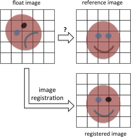
Fig. 10.2
The goal of image registration is to match a float image to the same coordinate space as the reference image. This can be done by applying global warping together with local alignment of structures
As the global as well as local morphology of the brain can significantly vary between different subjects, image registration is a challenging task. In addition to natural inter-subject brain variability, brain morphology can depend for example, on age, gender, and ethnicity. To make image registration even more challenging in the VBA setting, brain morphology can be significantly altered by the pathologies in patients that are studied.
Image Registration Techniques
The goal of this section is to provide some basi c background knowledge of image registration. Image registration can be considered as an optimization problem, for which the similarity between two or more images needs to be maximized iteratively [2]. The image registration problem can thus be subdivided into:
a method or algorithm used to find a maximal similarity
an approach to measure similarity between images
Image registration algorithms can be subdivided into two broad categories: global and local registration techniques.
Global image registration techniques apply the same deformation field (the matrix of numbers that defines how much a point is shifted), which transforms one data set to another, to all voxels of that data set. This can be done by rotating and translating the data set, referred to as a rigid–body transformation. In addition, global shearing (“stretching”) and scaling parameters can be added, then resulting in an affine transformation.
Local registration techniques determine a local deformation field for every voxel of the data set, in order to match every voxel with its corresponding voxel in the other data set.
A simplified example is given in Fig. 10.3, in which sagittal views of the brain, including the corpus callosum, are shown. In this example, the brain of subject X (shown in red) needs to be transformed to the template or atlas brain shown in blue. As a first step, the whole brain data set of subject X can be rotated and translated globally, in order to increase the similarity with the template brain. This registration technique, visualized in Fig. 10.3 by the purple box, is referred to as a rigid–body transformation . Subsequently, the resulting brain image can be scaled and skewed globally. The combination of the rigid-body transformation with additional global scaling and skewing is referred to as an affine registration (the purple and green boxes in Fig. 10.3). However, in order to obtain a better match of corresponding voxels in different data sets, local deformation fields need to be applied to the globally registered data set of subject X. This transformation is referred to as a non-rigid or non–affine registration and aims at aligning corresponding voxels of different data sets.
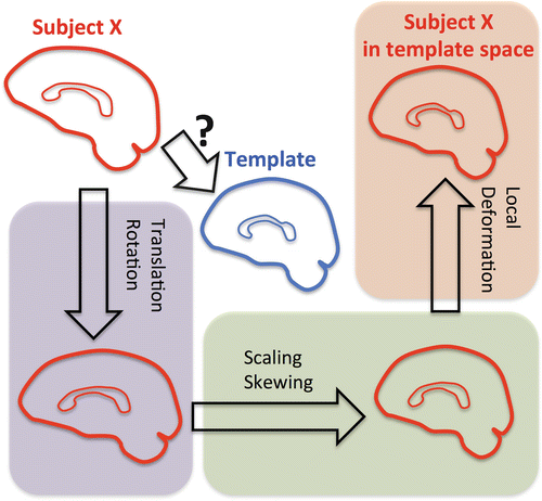
Fig. 10.3
Overview of the combination of global and local image registration techniques. To transform the brain of subject X to the template brain, both global and local image registration techniques are necessary. The purple box shows the rigid-body transformation, including global rotation and translation. In the green box, global scaling and skewing are added to the transformation, referred to as the affine transformation. The use of local deformations, as shown in the orange box and referred to as non-affine transformations, allows one to align both images on a local level
As aforementioned, an accurate image registration result is of paramount importance for a reliable VBA result. For example, if a non-affine registration would not be performed, the final registration result of subject X to the template would include a mismatch around the corpus callosum in this example (see Fig. 10.4). Because similar registration errors would be present for the other subjects, it is clear that a voxel-wise comparison of DTI measures would lead to unreliable results. Indeed, the DTI measures in voxels of subject X are then compared with the same measures in non-corresponding voxels of subject Y, which might be more similar to the atlas or contain different registration errors.
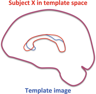
Fig. 10.4
Example of an affine registration result. Although both data sets are globally aligned, significant local image registration errors can be seen in the region of the corpus callosum
In order to optimize the image registration algorithms, appropriate image similarity measures need to be defined. In the end, it will be this image similarity measure that will be optimized to obtain the most optimal image alignment. Examples of similarity measures are the sum of squared intensity differences (SSD), cross correlation, and mutual information (MI). In the SSD approach, the intensity in corresponding voxels of two images is subtracted and the absolute value of the result is squared. The SSD is then calculated as the sum of this squared difference over all voxels in the image. A schematic example is shown in Fig. 10.5. The sagittal views of the affine registration result, which was shown in Fig. 10.4, are visualized in grayscale intensities. On the top row, the image X that was registered to the template, the template image, and the overlay between both are displayed, showing some misregistration of the corpus callosum. In the second row, the calculation of the SSD is schematically depicted, highlighting the mismatch regions. If a perfect registration could be performed, the SSD measure would be zero, demonstrating optimal image similarity.
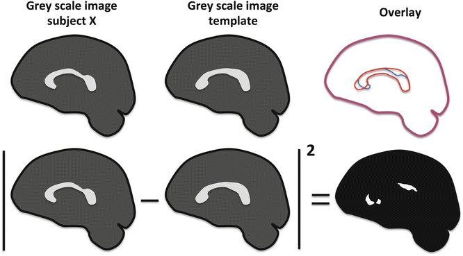
Fig. 10.5
An example of the sum of squared differences technique to measure image similarity. The intensities of the registered image and template are subtracted in every voxel and subsequently squared. Then, the total sum in every voxel is taken. When both images would be perfectly aligned, the sum of squared differences would be zero
The SSD is a simple approach to evaluate similarity between images. More advanced methods that can take into account different intensity values of similar structures in different images, such as mutual information, generally produce better results. In addition, some specific image similarity methods have been developed for DTI data, using information on tensors, statistical relationships between measures, or anatomical information. In contrast to typical grayscale MRI images, DTI data contain more information in each voxel; therefore similarity measures can be optimized to make use of this additional information [3, 4].
Summary Points
To register two images you need (a) a model (global and/or local) to warp the floating image to the reference image, and (b) a way to measure how well both images are aligned, in order to find an optimal registration.
Rigid-body registration involves only translations and rotations, whilst affine registration also includes scaling and shearing.
Examples of similarity measures include sum of squared intensity differences (SSD), cross correlation, and mutual information (MI).
Registration of DTI Data
The registration of DTI data is especially challenging. This is mainly caused by the fact that DTI data, unlike anatomical MRI or CT data, contain a tensor in each voxel, which also represents orientational information. Taking this tensor information into account can improve the registration result (an overview of DTI registration methods is provided in [5]). In the following paragraphs, we will describe several challenges in more detail.
DTI Registration Challenge 1: Reorientation
The tensor is directionally dependent and contains orientational information about the underlying white matter microstructure. When transformations are applied to align data sets, a correction (i.e., a tensor reorientation strategy) needs to be applied to ensure that the directional DTI information is still accurate.
The need for tensor reorientation after image alignment of DTI data or during iterative registration processes is explained in Fig 10.6. To simplify things, the concept of reorientation is explained for only one white matter fiber bundle, containing three voxels. Consider that in the original DTI data set of subject X, this bundle runs vertically. The DWI image intensities of the three voxels in that bundle are high for the DWI that was acquired with a diffusion sensitized gradient perpendicular to the bundle, and low for the DWI acquired with a diffusion sensitized gradient parallel to the bundle. For simplicity, only two DWIs are considered here. The corresponding white matter bundle of the template image, however, contains some curvature. As a result, the DWI intensities for the different gradients are different in these voxels.
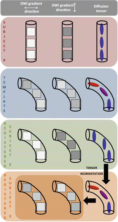
Fig. 10.6
Simplified overview of the tensor reorientation problem in DTI. Tensors indeed need to be reoriented after image registration in order to be aligned with the underlying microstructure
It is now assumed that we can align both white matter bundles perfectly, i.e., the corresponding voxels of the white matter bundle are perfectly registered. The resulting deformation field is then applied to the DWIs and the tensor is recalculated. Now, if we refer to Fig. 10.6 again, we see that the registration process changes the spatial location of voxels in order for them to match, but not their values or image intensity. However, if only the spatial location of the voxels is changed, and not their image intensities, the directional diffusion information, and therefore the tensor, are not changed compared to the information in native space. Indeed, as explained in Chaps. 4 and 6, the image intensities of the different DWIs and the values of the tensor are related to the orientation of the white matter bundle.
As a result, the tensor information of the registered data set of subject X to template space thus no longer reflects the underlying microstructural white matter information, as can be observed in Fig 10.6. In order to correct for this, Alexander and Gee [4] proposed different methods, referred to as the “finite strain” and the “preservation of principle directions” approach. The finite strain method decomposes the transformation matrix in a deformation and a rotation component, whereafter only the latter is used to reorient the tensors. However, shearing, nonuniform scaling, and stretching factors affect the orientation as well. Together with the rotational component, they are taken into account in the preservation of principal direction strategy.
When a global, i.e., rigid-body or affine, registration method is applied, the same reorientation is applied to all voxels. However, in the case of non-rigid registrations, the local transformation matrix, which can be different for each voxel, is used to calculate local tensor reorientation.
It is important to note that tensor reorientation approaches do not affect the rotationally invariant quantitative DTI measures, such as the eigenvalues, the FA, or MD. As they are rotationally invariant, reorienting the tensor does not change their values. In a VBA analysis, it is therefore not necessary to reorient the tensors if only the rotationally invariant, quantitative DTI information is used in the subsequent analysis.
DTI Registration Challenge 2: The Tensor Information
DTI image registration can be optimized by using information from other modalities, such as anatomical MRI, or by incorporating scalar and tensor information . Park et al. [6] compared the use of different input images on the overall registration result of DTI data. They evaluated registration results after using T2-weighted images, FA images, the difference of the first and second tensor eigenvalues, FA and the tensor trace, all three tensor eigenvalues, and finally the six independent tensor components [6]. In this study, it was demonstrated that the use of the six independent tensor components as input channels performed most optimal in aligning the tract morphology and tensor orientation. This was further confirmed by other studies [7].
Scalar Anatomical MRI Information, Such as 3D T1-Weighted Images
Using scalar anatomical MRI information to determine the deformation field between DTI data sets is similar to the approach used in functional MRI analysis. First, the DTI data set is transformed to the 3D T1-weighted image of the same subject, using a rigid-body or affine transformation. The DTI information used for this registration is normally the b0 or non-diffusion weighted image, as this image mostly resembles the anatomical image. Thereafter, the 3D T1-weighted image is aligned to a T1-weighted atlas, such as the Montreal Neurological Institute (MNI) template. The resulting deformation field is then applied to the DWIs, which were transformed into the space of the T1, or to the transformed quantitative DTI maps directly.
The advantages of this approach are:
T1-weighted atlases can be used.
Many open-source software packages support this type of algorithms, such as SPM (www.fil.ion.ucl.ac.uk/spm), FSL (www.fmrib.ox.ac.uk/fsl), AFNI (afni.nimh.nih.gov/afni).
However, using this approach is not optimal for DTI data, for several reasons:
The unique white matter DTI information is not used to guide the registration. The image intensity of white matter is uniform on T1-weighted images, which can result in mismatching of different fiber bundles [6, 8].
As DTI data sets are usually acquired using an EPI sequence, different artifacts are present compared to the T1 image. For example, geometric distortions due to eddy currents and susceptibility. This results in misregistration between the b0 image and T1-weighted image.
Scalar DTI Information, Such as FA or MD Maps
In this approach, the scalar DTI information, such as contained in FA or MD maps, is used as input information to guide the registration. As a result, no anatomical data sets are involved, and registration is directly performed based the DTI information. Compared to using anatomical information, this method has several advantages:
Some white matter information (as present in FA or MD maps) is used to increase the registration accuracy.
The DTI information is directly aligned to an atlas and no anatomical MRI image is needed.
Although this will increase registration accuracy, this approach has some drawbacks:
FA and MD values do not always discriminate fiber bundles that are located close to one another, potentially resulting in misregistration of these bundles.
There needs to be an FA template to align the subject data to.
Diffusion Tensor Information
Many approaches have been proposed that incorporate the specific DTI information into the registration process in order to increase registration quality. For example:
By including several channels of scalar image information. Guimond et al. [9] and Park et al. [6] have used different channels of input information, such as the T2-weighted image intensity, fractional anisotropy, trace of tensor, and eigenvalues.
By using the scalar information from the whole tensor to align two DTI data sets and detect correspondences between them [6, 7, 10–13]. In addition to using the tensor elements, DTI feature vectors can be derived and used to drive the registration ([14–16]).
It has been demonstrated that the use of DTI-specific information with multiple channels results in more accurate registration of DTI data. As an accurate image alignment is one of the most important assumptions in VBA, including DTI information during the registration will increase the reliability of the VBA results [6, 7]. However, some drawbacks of this approach should be mentioned:
As this approach is more complex compared to the scalar registration methods, computation time is increased.
There is a need for tensor information in atlas space, as this tensor information is needed to drive the registration.
Summary Points
In order to achieve successful DTI registration, the orientational dependence of the diffusion data needs to be accounted for, i.e., any rotation of the DWIs should be corrected for, e.g., by using tensor reorientation during affine registration.
Registration can be improved by incorporating diffusion information, such as scalar DTI measures (e.g., FA/MD), tensor information, or a combination of different data types.
Atlas or Template
The atlas or template is the reference frame to which all data are registered and which is used to report the results. It has been demonstrated that the choice of this atlas or template can affect the VBA results [21–23]. As a result, the atlas selection is an important step in the VBA processing pipeline for DTI data. An overview of possible DTI atlas selection approaches is provided in Zhang and Arfanakis [23].
DTI templates can be subdivided into two broad categories:
a standard template,
a population-/study-specific template
A population- or study-specific template is usually constructed based on the data sets that are analyzed. As a result, in theory, this atlas is the best representation of these data sets, and should thus result in minimizing the registration errors. A standard template, on the other hand, is an atlas that was created from a group of healthy subjects and is independent from the subject data sets that need analyzing. However, these atlases usually contain anatomical labels and predefined region of interests, which might be of interest for the study. So, again, there is no single correct approach of selecting an optimal template for your study. The optimal choice will depend on your study and data (i.e., goals, hypothesis, patient population, data quality). In the following paragraphs, a more detailed description of the template selection choice is provided, including some advantages and limitations of the different approaches.
Standard Template
Standard templates are typically constructed by averaging data from a group of healthy subjects that have been registered to a stereotaxic atlas. For example, anatomical T1-weighted templates were constructed by the Montreal Neurological Institute (MNI) and the International Consortium of Brain Mapping (ICBM) [24–26], and are widely used in functional MRI research. Mori et al. created the first standard DTI atlas in the ICBM space, containing fiber orientation maps and white matter parcellation maps [27]. Peng et al. [28] and Zhang et al. [21] created a DTI atlas in the ICBM-152 space by registering high quality DTI data sets of 67 healthy subjects using a non-affine registration procedure.
One of the main advantages of using standard templates is that they provide the possibility to make use of predefined anatomical regions for subsequent region-of-interest analysis in atlas space. Furthermore, as the standard templates are widely used, results, and coordinates of significant findings in particular, can be easily compared across studies.
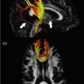
However, there are some drawbacks when using a standard template. First, as most standard templates are created from healthy subject data, they do not necessarily represent an average brain of the subjects of your study, especially when pathology is present in some subjects. A simplified example is given in Fig. 10.7. Assume again that DTI measures are compared between healthy subjects and patients with Alzheimer’s disease. Although some atrophy can be present in the healthy control group , it will be more severe in the Alzheimer’s group. As a result, when all data is transformed to a standard atlas of a healthy brain, the registration result will be much better for the healthy subject data compared to the Alzheimer subject data. This is especially notable at borders with CSF (shown in black in Fig. 10.7), where the groups will not be matched correctly. Not only will there be registration errors (something we don’t want in VBA), there is also a bias towards a certain subject group. As a result, this will create false positive findings, caused by more significant misregistration in one of the subject groups in specific brain regions.
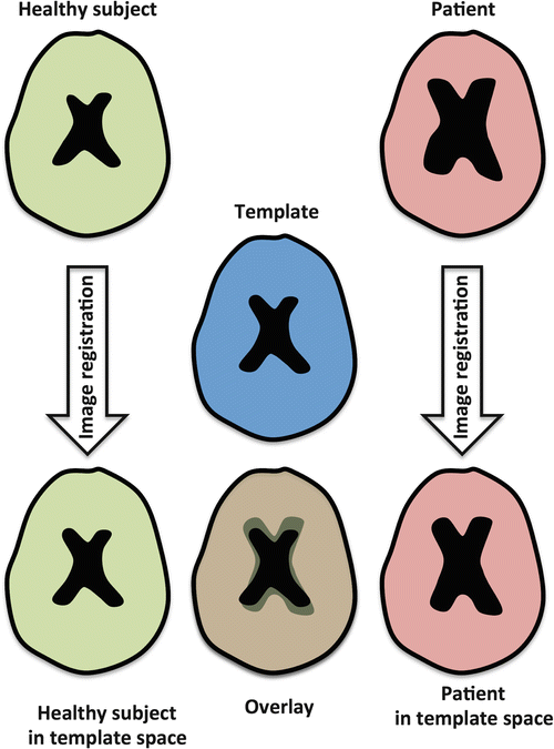
Fig. 10.7
A simplified example of image registration of healthy subjects and subjects with enlarged ventricles to a healthy subject atlas. Registration errors can occur in the group with enlarged ventricles, thereby introducing a potential bias in the VBA results
Another limitation of some standard templates is that the diffusion tensor information is not always present, hence limiting the information that can be used to drive the registration process to this atlas.
Population-Specific Atlas
The general idea of population- or study-specific atlases is to use the data sets that are studied to determine an atlas space, to which all data subsequently are registered. The simplest way to construct a study-specific atlas is to select one DTI data set from the study population as the template. This subject can be chosen randomly, based on visual inspection of all data or based on calculations that determine which subject is most representative for the population. In the latter case, all data sets are registered to each other and the deformation fields from one subject to all others are averaged. The subject with the smallest average deformation field to all other subjects can then be regarded as the most representative subject of the population under study.
Related posts:

Stay updated, free articles. Join our Telegram channel

Full access? Get Clinical Tree


