Introduction
Heart failure is a major cause of morbidity and mortality, contributing significantly to global health expenditure. Heart failure patients often exhibit contractile dyssynchrony, which diminishes cardiac systolic function. Cardiac resynchronization therapy (CRT), a relatively new treatment modality that employs biventricular (bi-V) pacing to recoordinate the contraction of the heart, is a valuable therapeutic option for such patients. CRT has been shown to improve heart failure symptoms and reduce hospitalization, yet approximately 30% of patients fail to respond to the therapy. In the current environment, which emphasizes reducing health care costs and optimizing therapy, robust diagnostic approaches to identify patients who would and would not benefit from CRT would have a dramatic personal, medical, and economic impact on the lives of many Americans.
The poor predictive ability of current approaches to identify potential responders to CRT reflects the incomplete understanding of the complex pathophysiologic and electromechanical factors that underlie mechanical dyssynchrony. The goal of this chapter is to present the development, from magnetic resonance imaging (MRI) and diffusion tensor (DT) MRI scans, of individualized three-dimensional (3D) image-based multiscale computational models of ventricular electromechanics that incorporate the deleterious structural, mechanical, and electrophysiologic remodeling associated with dyssynchronous heart failure (DHF), from the level of the protein to that of the intact heart. We then demonstrate how this powerful predictive modeling approach could be used to provide mechanistic insight into heart failure contractile dyssynchrony and to possibly determine the optimal CRT strategy.
The development of a predictive model of ventricular electromechanics in the setting of DHF overcomes the inability of current experimental techniques to simultaneously record the 3D electrical and mechanical activity of the heart with high spatiotemporal resolution and thus to provide an understanding of dyssynchrony and CRT effectiveness. The new basic-science insights into the electromechanical behavior that can be acquired with this modeling approach will hopefully lead to rational optimization of CRT delivery and to improvements in the selection criteria for potential CRT candidates.
Heart failure is a major cardiovascular disease affecting 5 million people in the United States alone and is associated with high morbidity and mortality rates.1 The syndrome is characterized by impaired pump function due to the deleterious remodeling of the ventricles, from the organ down to the molecular level, which significantly alters the electrical and mechanical behavior of the heart. High-resolution MRI and DTMRI scans2 have shown that in DHF, there is a substantial remodeling of ventricular geometry and structure. At the organ level, the ventricles become dilated, and wall thickness is reduced. At the tissue level, laminar sheet angle is altered, and the transmural gradient in fiber orientation is increased. Because chamber geometry and sheet structure are major determinants of left ventricular (LV) mechanics,3,4 the mechanical deformation of the failing heart is markedly different. Furthermore, altered heart geometry and fiber and sheet orientations directly affect 3D electrical propagation5 in the failing heart.
Heart failure is also characterized by remodeling of the electrophysiologic and mechanical properties at the cellular and subcellular levels. Studies6,7 have shown that the gap junctional protein connexin 43 (Cx43) is redistributed from the intercalated disk to the lateral myocyte borders and that the amount of hypophosphorylated Cx43 is increased, leading to reduced conduction velocity in heart failure. There is a considerable downregulation of the membrane potassium channels carrying the Ito and IKl currents8 and of the intracellular sarcoplasmic/endoplasmic reticulum Ca2+ ATPase (SERCA) pump9 and upregulation of the Na-Ca exchanger (NCX).9 Remodeled ionic currents and Ca2+ handling result in altered Ca2+ transients, which, in turn, impair active tension development by the myofilaments in the cell. Finally, differential expression of collagen isoforms10 and altered ratio of titin (an intrasarcomeric protein that modulates myofilament passive tension) isoforms11 result in increased myocardial stiffness.
Because of the combined effects of chamber, contractile, and electrophysiologic remodeling, the ability of the LV to efficiently pump blood is severely compromised in heart failure patients. Furthermore, a subset of these patients exhibits abnormal electrical conduction that delays activation of one portion of the ventricle relative to another (intraventricular conduction delay due to left bundle branch block [LBBB]). This results in contractile dyssynchrony (ie, DHF), which further diminishes cardiac systolic function and energetic efficiency.
CRT is an established therapy for DHF patients. CRT typically employs bi-V pacing, with an endocardial right ventricular (RV) pacing lead and an epicardial LV pacing lead, to recoordinate contraction.12 CRT has been shown to acutely and chronically improve systolic function13 of the heart and to reverse the detrimental remodeling14 associated with heart failure. Clinical trials of CRT have consistently demonstrated improvement in heart failure symptoms, exercise tolerance, and quality of life and a reduction in recurrent hospitalizations.15
Although CRT reduces morbidity and mortality,16 approximately 30% of patients fail to respond to the therapy.17 This reflects the poor predictive capability of current approaches to identify potential responders to CRT. The QRS duration (QRS ≥150 ms), which is widely used in clinical trials as a basic component of the inclusion criteria for CRT, does not provide an indication of the degree of mechanical dyssynchrony.18 Indeed, patients with long QRS duration may not exhibit mechanical dyssynchrony, and those with short QRS complexes may present with significant dyssynchrony in contraction.19-21 Measurements of mechanical dyssynchrony by Doppler echocardiography22,23 reveal only local dyssynchrony, whereas the complex deformations in DHF are global. In recent clinical trials, Doppler echocardiography demonstrated lack of repeatability and low predictive value.24,25 The poor predictive capability of the above measures indicates an incomplete understanding of the electromechanical behavior in DHF.
The presence of myocardial infarction is an additional reason for lack of response to CRT. Placement of a pacing electrode at or near the infarct scar may result in ineffective pacing and, thus, in failure of resynchronization. Because infarction modulates electromechanical interactions, it also alters the mechanism of CRT. Bleeker et al26 documented that patients with transmural posterolateral scar have a much lower response rate to CRT than those without scar (14% vs 81%, respectively). Increased scar volume has been found to result in unfavorable response to CRT.27 Infarct location and scar transmurality are considered important28,29 yet unknown factors that affect the relationship between electrical activation and contraction and contribute to diminished CRT efficacy.
Finally, the location of LV pacing has been shown to play an important role in CRT efficacy.30-33 Currently, LV pacing lead is implanted in a tributary of the coronary sinus, as in epicardial bi-V pacing.19,34 However, for a small class of patients unsuitable for transvenous bi-V, a transseptal approach has been developed that allows endocardial bi-V pacing.35,36 Recent studies have brought to light the potential proarrhythmic effect of epicardial bi-V pacing,37 resulting from the reversal of the direction of electrical propagation in the LV. Furthermore, new findings indicate that endocardial bi-V pacing might be associated with improved resynchronization in canine models38,39 and humans.40,41
A comprehensive characterization of the spatiotemporal electromechanical interactions in the DHF heart is paramount to any improvement in the selection criteria for viable CRT candidates and is fundamental to the effort toward improving CRT efficacy. The development of a multiscale model of ventricular electromechanics offers a powerful methodology to unravel the mechanisms by which the deleterious structural, mechanical, and electrophysiologic remodeling in DHF, from the scale of the protein to the intact organ, causes discord between electrical activation and mechanical contraction of the heart. This unique and novel tool overcomes the limitations of previous approaches to elucidating cardiac electromechanical interactions and provides insights that cannot be obtained by experiment alone.
In the last decade, simulation research in cardiac electrophysiology has made important steps forward in linking models of myocyte action potential to geometrical models of cardiac tissue and the entire organ (see review by Trayanova and Tice42). Although integrative multiscale models of organ behavior that incorporate detailed biophysical models of the myocyte cellular and subcellular processes43-45 are not yet commonplace, they have nonetheless made major contributions to obtaining insight into electrical excitation46 and the mechanisms of arrhythmogenesis47-49 and defibrillation50,51 in the normal and, in some cases, the diseased heart.52 Similarly, finite element continuum models incorporating anatomy, structure, and passive mechanics have been developed,53,54 and recently, attempts have been made to couple them to biophysical models of cellular active tension.55,56 The development of models of these two major physical processes in the heart has occurred largely independently. However, in the last few years, coupled models of cardiac electromechanics, in which contraction is triggered by the electrical event, have also been assembled.55-66 All of these models incorporate major simplifications in the representations of membrane dynamics,58,60 triggering process for contraction,57,59,61 cellular active tension,57,60,65 and tissue/organ geometry and structure.55,56,59 In addition, with very few exceptions,63,66 these models represent electromechanical activity in the normal heart. Simplifications limit the models’ predictive capabilities, particularly their utility in simulating the acute effects of CRT. Indeed, models addressing CRT include those representing bi-V pacing in the normal heart without accounting for cardiac mechanics67,68 or simulating mechanics with a simple two-element rheologic model.61 Even the most sophisticated models of CRT62-64 use phenomenologic representations of membrane dynamics that do not incorporate remodeling in heart failure.
The multiscale electromechanical model of DHF presented here is a major step forward in representing the detailed electromechanical interactions in the remodeled heart, from the protein to the organ level, overcoming limitations of previous model developments. Furthermore, we incorporate, for the first time, individualized image-based organ and structure in the models, thus ensuring that the mechanistic insights that can be obtained with the model are directly applicable to the clinical setting and the clinical CRT procedure.
Image-Based Electromechanical Model of the Heart
Figure 13–1 illustrates the pipeline for assembling image-based models of the heart by showing the processing of an example image slice. It is important to note that the models generated in this way will retain fine structural details, such as endocardial trabeculations and papillary muscles, provided that such structural details are resolved by the ex vivo imaging method. Further details on the processing pipeline can be found in our recent publications.69-71
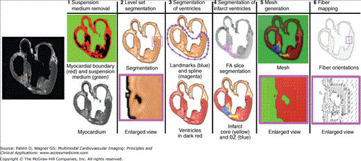
The ex vivo structural MRI is processed to label and “remove” voxels corresponding to cavity content and surrounding medium. First, the image edges are detected,72 and the myocardial boundary of the heart is extracted using a region-growing algorithm.73 The surrounding medium is removed by assigning the background intensity to all voxels in the medium. The result is an image of the myocardium (step 1 in Fig. 13–1). In step 2, the myocardium is separated from the large coronary arteries.
In each slice, ventricular tissue is labeled by fitting a closed spline curve through spline points placed around the ventricles and along the atrioventricular border. All voxels that belong to tissue inside the curve are marked as ventricular (step 3 in Fig. 13–1). Ventricles and atria are then separated.
Often patients with DHF also have myocardial infarction. Therefore, we included in our model reconstruction pipeline the capability to segment the zone of infarct. From the DTMRI, a 3D fractional anisotropy (FA) image is constructed.74 FA is a measure of the directional diffusivity of water. Based on the difference in FA values,75,76 the infarct region is separated from the normal myocardium. Next, the infarct region is subdivided into two areas, an inexcitable scar and a peri-infarct region,75,76 which is assumed to contain excitable and contracting but pathologically remodeled tissue, by thresholding the structural MRI based on voxel intensity values 77 (step 4).
Next, a finite element tetrahedral mesh is generated from the segmented MRI for the solution of the electrical component of the model. The mesh requirements are based on the spatiotemporal characteristics of wave propagation in the heart; it has been shown that a spatial resolution of approximately 250 μm is appropriate for electrophysiologic finite element models of the heart.78,79 A novel approach was recently published by our team80 for image-based mesh generation. The electrical meshes of the heart used in the preliminary studies were generated using this methodology. Step 5 in Fig. 13–1 shows the mesh for the example slice, whereas Fig. 13–2A presents the electrical mesh of the entire canine heart. The meshing technique is automatic and produces boundary-fitted, locally refined, and smooth conformal meshes (see Fig. 13–2A, inset). The local adaptation of the resolution, as shown in Fig. 13–1 (step 5), significantly reduces the number of elements in the mesh without compromising geometric detail. Note that we typically generate electrical meshes of the heart that incorporate both ventricles and atria. However, the electrical problem is effectively solved only on the ventricular portion of the mesh because atria and ventricles are electrically isolated.
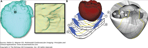
The mechanical mesh consists of hexahedral elements with Hermite basis. This choice of finite elements maintains continuity of strain and is appropriate for maintaining incompressibility constraints.81 The mechanical mesh is also generated from the segmented images and based on the electrical mesh to ensure exact match in geometries; for mechanical mesh generation, we use only the segmented ventricles. The methodology to construct image-based mechanical meshes has been recently developed by our team.82 The mesh is constructed from a sheet with a thickness of two elements that is “wrapped around” the segmented ventricles as shown in Fig. 13–2B. Note that current mechanical meshing procedures58,83,84 introduce an artificial hole in the LV apex; the meshing procedure described here avoids this artifact.
Fiber and laminar sheet organization underlie the orthotropic electrical conductivities of the tissue and the tissue mechanical properties. We recently developed a methodology to interpolate DTs from the DTMRI data onto the elements in both meshes, thus mapping the fiber and laminar sheet organization onto the meshes (ie, defining the orthotropic properties of the myocardium for the solution of the electrical and mechanical problems). To incorporate fiber and laminar sheet architecture in the model, tensors and tensor gradients were defined at each node of the finite element mesh and interpolated within the finite elements using Hermite interpolation. The eigenvectors of the tensors in the interpolated tensor field represented the fiber and laminar sheet structure in the reconstructed hearts.
Interpolation is performed in a vector space of tensors, introduced previously by Arsigny et al,85 in the framework of which addition of two tensors, A1 and A2, and multiplication of a tensor A by a scalar k of the vector space were:
For positive definite symmetric matrices, these operations become:
where U is an orthogonal matrix and D is a diagonal matrix of eigenvalues λ1, λ2, and λ3. Using the operations in Equations 13-1 and 13-2, the Hermite interpolation is defined as:
where Ψi are the Hermite basis functions described in Nielsen et al83 and A1 are the tensors and tensor gradients with respect to the arc lengths assigned to the nodes of each finite element.
Related posts:

Stay updated, free articles. Join our Telegram channel

Full access? Get Clinical Tree


