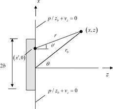
, and a normal velocity,  , are produced over the face of the element and that over the remainder of the plane z = 0 outside the element either the velocity or pressure (or combinations of velocity and pressure) are specified. If the surface outside the element is a pressure-free surface, then we would have
  on that surface. If instead the element is imbedded in a rigid “baffle”, then we would have
  on the baffle. Although both of these types of conditions are commonly used in modeling large, single element transducers, neither of these extreme conditions may hold for an element in an array since the array elements are often embedded in a surrounding matrix of material that has a different acoustic impedance from the piezoelectric element or has facing layers that have a different acoustic impedance from either the element or the surrounding fluid. Techniques such as finite elements can be used to model in detail these features of an array element but here we want to develop a much simpler model that can examine the effects of the boundary conditions surrounding an element (see Pesque and Fink [1] for a similar approach). Specifically, we will model the array element as embedded in a baffle having a finite specific acoustic impedance,
  , where on the baffle the condition

 then corresponds to the rigid baffle and the case
  models the pressure-free surface. Other finite values of the baffle impedance can then be used to model conditions that are in between these two extreme limits.

 , having the dimensions of a velocity, but which we see from Eq. (14.2) is not the actual velocity on the face of the element. Taking the Fourier transform of Eq. (14.2) gives
 in the form of an angular spectrum of plane waves . Specifically, we will write:
![$$p\,(x,z,\omega )=\frac{1}{2\text{ }\!\!\pi\!\!\text{ }}\int_{-\infty }^{+\infty }{\left[ P({{k}_{x}})/{{z}_{b}}+V({{k}_{x}}) \right]G({{k}_{x}})\exp \,(\text{i}{{k}_{x}}x+\text{i}{{k}_{z}}z)\,\text{d}{{k}_{x}}},$$](/wp-content/uploads/2016/05/A314073_1_En_14_Chapter_Equ4.gif)

 is the wave number for pressure waves in the fluid. Since the right side of Eq. (14.4) is a superposition of plane waves and inhomogeneous waves , both of which are exact solutions of the Helmholtz equation , the pressure
  in Eq. (14.4) will also be an exact solution to that equation. The “amplitude” terms
  in Eq. (14.4) are at present undefined. The particular combination of these terms given in Eq. (14.4) was chosen simply to help satisfy the boundary conditions of Eq. (14.3), as we will now show. First, we note that from the equation of motion of the fluid in the z-direction, the pressure and the z-velocity must satisfy the differential relationship [Schmerr]
 we find
 is the specific impedance of the fluid.
![$$\begin{matrix} p\,(x,z,\omega )/{{z}_{\text{b}}}+{{v}_{z}}(x,z,\omega )=\frac{1}{2\text{ }\!\!\pi\!\!\text{ }}\int_{-\infty }^{+\infty }{\left[ P({{k}_{x}})/{{z}_{\text{b}}}+V({{k}_{x}}) \right]} \\ G({{k}_{x}})\left[ \frac{1}{{{z}_{\text{b}}}}+\frac{{{k}_{z}}}{k{{z}_{\text{f}}}} \right]\exp \left( \text{i}{{k}_{x}}x+\text{i}{{k}_{z}}z \right)\text{d}{{k}_{x}} \\ \end{matrix}.$$](/wp-content/uploads/2016/05/A314073_1_En_14_Chapter_Equ8.gif)

![$$p\,(x,z=0,\omega )/{{z}_{\text{b}}}+{{v}_{z}}(x,z=0,\omega )=\frac{1}{2\text{ }\!\!\pi\!\!\text{ }}\int_{-\infty }^{+\infty }{[P({{k}_{x}})/{{z}_{\text{b}}}+V({{k}_{x}})]}\exp \text{(i}{{k}_{x}}x)\text{d}{{k}_{x}},$$](/wp-content/uploads/2016/05/A314073_1_En_14_Chapter_Equ10.gif)
![$$P({{k}_{x}})/{{z}_{\text{b}}}+V({{k}_{x}})=\int_{-\infty }^{+\infty }{\left[ p(x,z=0,\omega )/{{z}_{\text{b}}}+{{v}_{z}}(x,z=0,\omega ) \right]\exp \,(\text{i}{{k}_{x}}x)\text{d}x}.$$](/wp-content/uploads/2016/05/A314073_1_En_14_Chapter_Equ11.gif)

 is just the spatial Fourier transform of the right side of Eq. (14.3), i.e.
 and
and  can be identified as the spatial Fourier transforms of the fields
  and
and  , respectively, given by
![$$ p\,(x,z,\omega )=\frac{1}{2\text{ }\!\!\pi\!\!\text{ }}\int_{-\infty }^{+\infty }{{{V}_{0}}({{k}_{x}})\left[ \frac{{{z}_{\text{b}}}{{z}_{\text{f}}}}{{{z}_{\text{f}}}+{{z}_{\text{b}}}{{k}_{z}}/k} \right]}\exp \,(\text{i}{{k}_{x}}x+\text{i}{{k}_{z}}z)\,\text{d}{{k}_{x}}. $$](/wp-content/uploads/2016/05/A314073_1_En_14_Chapter_Equ15.gif)
 . If we also assume that the driving velocity term,
  , is spatially uniform over the face of the transducer, i.e.


 , acting on the element face and the average velocity in the z-direction,
  , on the face as
 , as
, as

Stay updated, free articles. Join our Telegram channel

Full access? Get Clinical Tree


