Fig. 1.
(a) Cut through of an Olympus IX81 fully motorized epi-fluorescence microscope showing details of the fluorescence light path. (b) Detailed view of the epi-illumination arm for the IX81 microscope showing details of the fluorescence light path. Images (a, b) are courtesy of Michael Davidson, Florida State University, National High Magnetic Field Laboratory, Tallahassee, FL. (c) Schematic of a fluorescence cube for EGFP imaging. Blue light is selected from the white incident light from the lamp using a blue band pass excitation filter. The blue light reflects off the dichroic mirror and is directed upwards to the objective lens then focused on the sample. Green emission light from the sample passes through the dichroic mirror and through a green band pass emission filter to the detector. The emission filter also reduces image background by rejecting any reflected blue incident light.
The subsequent component in the optical train is the fluorescence filter cube (Fig. 1a, b). The first filter in the cube is the excitation filter (Fig. 1c). It is typically a band pass filter that selects a specific range of wavelengths of light from the white light source in order to excite the fluorophore of interest. For example, for EGFP excitation a 470/40 blue band pass filter could be used. The filter nomenclature gives the central transmitted wavelength (470 nm) followed by the band width (40 nm). Thus, the 470/40 filter will transmit light between 450 and 490 nm (Fig. 2a, solid line and solid line with open circles). Incident light then comes to a dichroic mirror (mounted at 45°), which is designed to reflect light below a certain wavelength and pass light above that same wavelength (Fig. 1c; Fig. 2a, dashed line and line with triangles). The selected excitation light is reflected off of the dichroic mirror and is directed at 90° towards the detector. For an inverted microscope, the incident excitation light travels up through the objective lens and is focused onto the sample. The fluorophores within the sample are excited and give off fluorescence. Some light energy is always lost during the fluorescence process, so the emission light is always of lower energy (longer wavelength) than the incident light (e.g., blue light is used to excite green probes). This shift to a longer wavelength is termed the Stokes shift of the fluorophore (11). Fluorescence will be emitted from the dye molecules within the sample in all directions. The emission light reaching the objective lens is focused down through the microscope and passes through the dichroic mirror (Fig. 1c).
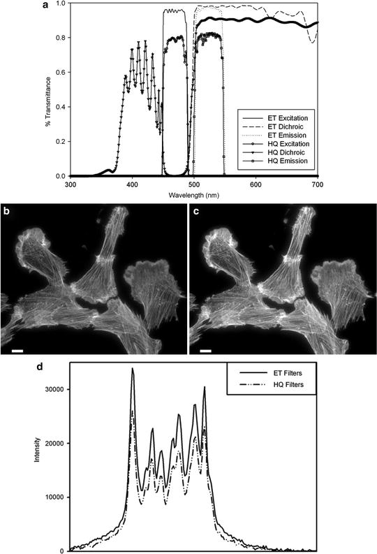
Fig. 2.
(a) Filter transmission curves for EGFP cubes using either standard soft coated filters (HQ series) or hard coated filters (ET series) from Chroma Technology. Cells stained with phalloidin AlexaFluor® fluorophore 488 (Invitrogen) were imaged on a Zeiss Axiovert 200 M microscope with a 63×/1.4 NA oil immersion lens and Axiocam HR camera at full resolution with 500 ms exposure times. Images were taken with either (b) the Zeiss soft coated 13 FITC; or the (c) Chroma Technology ET-GFP 49002 filter cube sets. The mercury lamp was attenuated to 5% power with neutral density filters. The image contrast, brightness, and gamma factor were all adjusted to the same levels for images displayed in (b, c). (d) Intensity profile from the white line shown in (b, c) for the hard coated ET (solid line) and soft coated HQ (dashed and dotted line) filter sets. The gamma factor was used to bring up dim features so that they are visible by eye within the images. Scale bar is 10 μm.
The final filter within the cube is the emission filter which is green for an EGFP cube (525/50), and is designed to both pass fluorescence emission and block any potential reflections from the incident light that may have passed through the dichroic mirror (Figs. 1c and 2a, dotted line and line with open squares). Most modern fluorescence microscopes are equipped with a multi-position filter cube turret so that multiple fluorescence cubes can be moved in and out of place rapidly. With motorized microscopes these turrets can be automated to facilitate multicolor image acquisition over time (10). Fluorescence emission is then either directed to the eyepieces generating an image on the retina of the observer or sent through another microscope port to a camera detector. The key components of the optical train and how to choose them appropriately will be discussed in detail in the following sections.
3 Components
3.1 Light Sources
(a)
Tungsten-Halogen: An incandescent tungsten-halogen bulb (50–100 W) is placed inside of a reflective housing. Lamp intensity is controlled by varying the applied voltage on the bulb. These lamps are typically used for bright field applications but can be used for fluorescence imaging as well (12). Tungsten-halogen lamps use inexpensive bulbs that are long lasting and do not need to be aligned. In addition, for fluorescence live cell imaging there is reduced photo-toxicity due to the low incident light power and the lack of a UV light component. However, since there is no UV component these lamps cannot be used to image blue dyes, and sometimes the power levels are not high enough to image weak fluorophores such as cyan fluorescent protein (CFP).
(b)
Mercury and Xenon Arc: The HBO mercury vapor arc lamp is commonly used for fluorescence microscopy. The lamp is a white light source but the spectrum shows many bright intensity peaks. Thus, the power of the excitation light for different wavelengths is NOT uniform from the UV to the IR range of wavelengths (13). Bulbs are expensive, last only about 200 h, their brightness decays over time, and they have to be disposed of in hazardous waste due to their mercury content. The bulbs also have to be precisely aligned in order to ensure an even illumination across the field of view. At lower magnifications there is typically nonuniform illumination, even if the lamp is well aligned, resulting in a field of view with a bright center. This nonuniformity should always be corrected for when performing quantitative imaging. Details on how to perform this correction will be presented later in this chapter. Arc lamps are intense and can be used to see even very dim fluorescent samples. Typically, it is best to attenuate these lamps using ND filters (to <10%). With reduced incident light, longer camera exposure times will be required in order to generate high S/N images; however photo-bleaching will be reduced. The XBO xenon arc lamp has a much more even intensity profile across the visible spectrum and into the IR wavelengths (13). This makes it ideally suited for quantitative fluorescence imaging. In general, it is not as intense as the mercury lamp, especially at wavelengths where the mercury lamp spectrum shows intense peaks. Xenon bulbs suffer from the same issues as mercury bulbs. They are expensive, have a short lifetime, and their brightness decays over time.
(c)
Metal Halide (e.g., Chroma Technologies-Photofluor; Lumen Dynamics—X-cite ® ; Zeiss-Illuminator HXP 120): Metal halide lamps offer many advantages over mercury arc lamps. The bulbs last about ten times longer (>1,500 h) and come with the reflector attached, so there is no bulb alignment required. The light is coupled to the microscope by a liquid light guide providing uniform excitation intensity across the microscope field of view. The liquid light guides do have to be replaced every couple of years. However, if there is an internal shutter within the light source, the life of the light guide can be extended. This would also negate the need for an internal shutter within the microscope. The metal halide lamp emission spectrum is similar to the mercury arc lamp, but the intensity between peak illumination bands is up to 50% brighter. This allows for access to the excitation of a broader range of fluorophores (10).
(d)
Light emitting diodes (LEDs): The most recent light source technology is based on LEDs. Commercial systems that are currently available include the Colibri™ (Carl Zeiss, Jena, Germany) (14), PrecisExcite™ (CoolLED Ltd., Hampshire, UK), LED4C (Thorlabs, Newton, NY), X-Cite® X-LED1 (Lumen Dynamics, Mississauga, ON), DM IL LED (Leica Microsystems, Wetzlar, Germany), and AURA light engine (Lumencor Inc., Beaverton, OR). Highly affordable systems can also be custom built with LEDs that are commercially available (15, 16). Essentially, the lamp consists of a number of discrete LED light sources each of a different color with relatively narrow bands of wavelengths. The LEDs can be turned on and off electronically within milliseconds. This eliminates the need for a mechanical shutter for the lamp. In many cases, excitation band pass filters are no longer required. However, many of the LED sources in the green to yellow region of the spectrum are relatively broad (>50 nm) and do require excitation filters in order to avoid the excitation of multiple dyes with one LED. The lamp brightness does not decay over time and ND filters are not needed since LED intensities can be precisely controlled electronically. LED lifetimes are on the order of 10,000 h and they are only turned on during image acquisition. LEDs eliminate the bleed through of unwanted wavelengths (e.g., UV, IR) found with arc lamps and filter-based wavelength selection; they do not produce heat and do not require any alignment. The disadvantages are that systems directly coupled to the microscope often have only three to four different wavelength LEDs available at one time. Other systems combine seven to eight LEDs together making a white light source that can be coupled to the microscope with a liquid light guide. The LED power levels have been steadily increasing making them suitable for photo-bleaching and photo-activation experiments.
(e)
Monochromator: The DeltaRAM X™ (Optical Building Blocks Corp.) and the RatioMaster™ (Photon Technology International, NJ) are commercially available monochromators with ∼2 ms switching times between excitation wavelengths. These slit-based systems allow the width of the band pass to be adjusted giving a lot of flexibility so that virtually any dye excited from the UV to the visible range (250–650 nm) can be imaged with a few dichroic mirror sets. These systems eliminate the need for excitation filter wheels making them ideal for rapid ratio imaging. Nonetheless, monochromators suffer from the same drawbacks as the light sources they use, which are typically Xenon Arc lamps.
Objective Choice: Phase contrast objectives should not be used in combination with fluorescence microscopy because the phase ring in the objective blocks some of the fluorescence emission light. DIC objectives are preferred when combined with fluorescence imaging. However, the DIC prism and analyzer should be removed from the light path during fluorescence imaging to avoid large losses in light throughput (17). The brightness (efficiency of transmission of excitation light and collection of emission light) of any objective lens is proportional to the numerical aperture (NA) of the lens to the fourth power and to the inverse of the magnification (M) squared (18, 19).
This should be taken into consideration when choosing between different objective lenses. For example, a 60×/1.4 NA oil immersion lens will have a higher light throughput than a 100×/1.4 NA lens with the same resolving power. In fact, a 40×/1.2 NA water immersion lens will have ∼20% higher light throughput than a 60×/1.4 NA lens at the expense of some resolution. Since the NA dependence is to the fourth power even small changes in NA can lead to drastic changes in lens brightness. For example, when comparing three 20× lenses, a 0.75 NA lens has the highest brightness (Fig. 3c). A similar 20× lens with a 0.5 NA loses about 60% of the light (Fig. 3b), while a 0.4 NA 20× lens loses 77% (Fig. 3a). In general, the lowest magnification needed to see the features of interest should be used because higher magnification decreases brightness with a squared dependence. Ordinarily, plan-apochromatic lenses are recommended because they are corrected for field curvature, spherical aberrations, and chromatic aberrations. In other words, images are in focus in the center and at the edges of the field of view, there is little distortion when focusing through the sample, and focus differences between different colors are minimized.
Fig. 3.
Images of BPAE cell slide from Molecular Expressions labeled with DAPI, AlexaFluor® 488 Phalloidin, and MitoTracker® CMXRos. Images were collected on an Olympus IX71 microscope coupled with a mercury HBO lamp and using DAPI, FITC, and Texas Red BrightLine® hard coated filter sets (Semrock). Images were collected on a Retiga 2000R camera at full resolution with the same settings using three different 20× lenses. The lamp intensity was attenuated to 6%, with exposure times of 250 ms for DAPI, 1,000 ms for AlexaFluor® 488, and 500 ms for MitoTracker® used. Lenses used were (a) Plan 20×/0.4 NA; (b) UPlanFL N 20×/0.5 NA; (c) UPlanSApo 20×/0.75NA. Images of the same sample as in (a–c) were collected using a 40×/NA 0.6 LWD, U PLAN FL lens with a coverslip thickness correction collar. Images were collected with the collar set correctly to 0.17 mm (d) or incorrectly to 1 mm (e). The image contrast, brightness, and gamma factor were all adjusted to the same levels for the images displayed in (a–c) as well as and for (d, e). The gamma factor was used to bring up dim features so they are visible by eye within the images. Scale bar is 10 μm.
All high NA immersion objectives are corrected for imaging through a glass coverslip that is ∼170 μm thick; therefore, it is important to mount samples using #1.5 coverslips and not the thinner #1 or thicker #2 coverslips. Some objectives actually have a correction collar that can be adjusted such that samples on glass or thick plastic tissue culture plates (∼2 mm thick) can be imaged with the same lens. It is important to adjust the correction collar for the correct substrate thickness or images will appear blurry and of low resolution (Fig. 3d, e). If imaging more than a cell layer or two, it is also important to match the index of refraction of the media to the lens. Water immersion lenses are often better when working with thick biological samples, because there is a reduction in spherical aberrations when imaging into aqueous media when compared to oil (20).
Filter Choice: Traditionally, fluorescence filters and mirrors have been designed using “soft” coatings whereby layers of low-optical-index material are evaporated onto optical quality glass surfaces. Blocking and transmission of different wavelengths of light to different degrees depends on the thickness, number of layers, and the order that the different types of materials are coated onto the filter. These coatings are often made on colored glass to further block undesired wavelengths of light, but this causes a reduction in transmission of specific wavelengths as well. “Soft” coated filters are not very durable, are difficult to clean without damaging the coatings, and degrade over time due to exposure to high intensity light and humidity. Recently, technologies for reliably producing “hard” coated filters by depositing metal-oxide films on optical quality glass have been developed (Chroma Technology—ET Series, Omega Optical—QMAX, Semrock—Brightline) (21, 22). These filters are very robust, do not degrade under normal conditions within the microscope, and are atomically flat thereby reducing nonspecific light scatter. Since the metal-oxide layer thickness can be precisely controlled, these filters have much better blocking and transmission properties as well as sharper cutoffs between blocking and transmission wavelengths (Fig. 2a, compare HT (Hard coated) with the HQ (Soft coated)). Images taken with traditional soft coated filters (Fig. 2b, d) are ∼30% dimmer than images taken with exactly the same imaging conditions using a hard coated ET-GFP filter (Fig. 2c, d). Importantly, since the efficiency of fluorescence light transmission is nearing 100%, the incident lamp power can be reduced, minimizing photo-bleaching, photo-toxicity, and background. It is recommended to replace soft coated filters with “hard” coated filters. The new filter sets can be mounted in existing filter cubes so the cost of upgrading is minimal. This is especially important for live cell applications in order to reduce photo-toxicity.
For multicolor imaging, if time is not an issue, it is best to image each fluorophore separately with single fluorophore fluorescence cubes. If speed is an issue, or the filter turret is not motorized, then multiband mirrors can be used in place of dichroic mirrors. There are two main disadvantages when using multicolor cubes: (1) to avoid excitation and emission cross-talk between different dyes, the band pass filtering for both the excitation and emission filters has to be very narrow; (2) the coating on the multi-chroic mirror for excitation of one dye often reflects fluorescence from another dye. For example, red fluorescence is excited by green light, but some of the light coming from the green dye will also reflect off the mirror and will not be detected. Taken together these factors result in multicolor cubes having a much lower light throughput.
Cameras: Charge-coupled device (CCD)-based cameras are most commonly used for high resolution fluorescence imaging. In general, color cameras should not be used for fluorescence imaging because they have lower resolution and lower sensitivity than monochrome cameras. Most color CCD cameras use a Bayer filter placed over the CCD pixel array making 25% of the pixels red, 50% green, and 25% blue. Therefore, much of the emitted light is not collected (Compare Fig. 4a, b) and the resolution is lower (Compare Fig. 4c, d). In this example, images were collected with exactly the same conditions, but with the color camera only ∼12% of the blue light, ∼20% of the green light, and ∼11% of the red light is detected relative to the monochrome camera (Fig. 4). Therefore, it is preferable to use red, green, and blue filter sets, take three images on a monochrome camera, and overlay them with software post-acquisition.
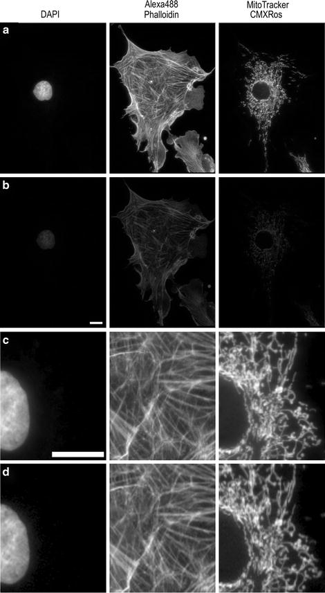
Fig. 4.
Images of the same sample collected on the same microscope as in Fig. 2.2. Images were captured with a Retiga 2000R monochrome (a, c) or color (b, d) camera at full resolution with a 60×/1.42 NA, PlanApoN objective. All images were collected with the same settings with the lamp intensity attenuated to 6% and exposures of 200 ms for DAPI, 500 ms for AlexaFluor® 488, and 50 ms for MitoTracker®. Images in (a, b) are presented with the same image display settings. The gamma factor is used to bring up dim features so they are visible within the images. Images in (c, d) are zoomed in areas of the images in (a, b). Images in (d) were further adjusted for brightness and contrast so they appear to have similar brightness when compared to (c) in order to provide a fair comparison of the image resolution.
There are many ways to automate multicolor imaging. For maximum sensitivity it is best to put the different filter cube sets for each dye in a motorized microscope turret. For increased speed a multiband dichroic mirror can be used in combination with excitation and emission filter motorized filter wheels. LED- or monochromator-based light sources can be used instead of excitation filter wheels. Liquid crystal filters (e.g., QImaging Corporation, Tucson, AZ) can be used to select for red, green, or blue emission; however a lot of light is also lost. For maximal sensitivity and speed, there are color cameras equipped with three CCD chips and filters within the camera head to split the light to red, green, and blue components with minimal light loss and no resolution loss (e.g., ORCA-3CCD, Hamamatsu, Japan). Many of the high resolution scientific grade CCD cameras on the market are based on the Sony ICX285 sensor with 1,392 × 1,040, 6.45 × 6.45 μm pixels (e.g., Andor Technologies Clara; Hamamatsu OrcaER; Photometrics CoolSNAP ES2; QImaging Retiga EXi). This chip has a quantum efficiency (QE) of 60–70% in the visible range meaning 60–70% of the photons that reach the camera will be detected. What differs between the manufacturers is the electronics surrounding the chip and the acquisition software. All cameras should be tested for a given application before a purchase is made.
For high speed applications, newer electron multiplied (EM) CCD cameras are recommended. The EM-CCD sensor array includes an electron multiplication gain register that all pixel signals pass through before being read out, thus signal, but not read noise, is amplified. The top of the line EM-CCD cameras use back thinned sensors with >90% QE in the visible range (e.g., Andor Technologies iXON; Hamamatsu ImagEM; Photometrics Evolve; QImaging Rolera MGi Plus).
There are also high resolution EM-CCD models with a 1,024 × 1,024 pixel array with 13 × 13 μm pixels; however, these chips are not back-thinned so the QE is in the 60–70% range (Andor Technology LucaEM; Hamamatsu ImageEM 1K; Photometrics Cascade II:1024). Nevertheless, if speed is not an issue standard CCD sensors still have at least twice the resolution when compared to EM-CCDs. A nice option is to have a high resolution CCD camera on one detector port of the microscope for high resolution imaging and an EM-CCD on another detector port for high speed imaging. Devices are also available to split multiple colors of light onto the two halves/quarters of the CCD array allowing for simultaneous two/four color imaging (Dual-View, Quad-View—Photometrics, Tuzson, AZ), which is great for high speed applications.
Cooling of cameras to 0°C or slightly below is usually significant for the exposure times used with biological samples. Cooling to below −30°C is typically not necessary as dark currents (caused by thermal noise) are not significant with exposure times of a few seconds or less. More information on cameras for fluorescence microscopy is also available (23–25).
Finally, the latest development in camera technology is the advent of scientific CMOS (sCMOS) camera technology (Andor Technology—Fairchild Imaging—PCO.imaging sCMOS; Orca-Flash2.8—Hamamatsu). Early results suggest that these cameras have the potential to replace CCD devices with similar sensitivity, higher imaging speeds, lower noise, and higher resolution.
4 Fluorescence Probes and Immunofluorescence
Introduction to Fluorescence: This section will serve as a brief introduction to the process of fluorescence. Readers are referred to other publications for more in-depth discussions (11, 26, 27). Incident lamp excitation light is focused by the objective onto a fluorescently labeled specimen. Fluorophores within the specimen absorb light energy and consequently enter the singlet excited state. The singlet excited state is unstable and therefore the molecules want to emit excess energy and relax back to the ground state. Some of the excited molecules can relax back to the ground state by emitting light energy in the form of fluorescence. Some energy is inevitably lost through vibrations of the molecule during this process, so emitted fluorescent light is always of lower energy, or longer wavelength, than the incident light. This process is termed the Stokes shift (11, 27) and allows for the separation of the excitation light and the emission light using filters. During epi-fluorescence microscope imaging, incident light is continuously exciting fluorophores within the specimen. Each fluorophore will cycle between the ground state and the excited state, repeatedly giving off many photons of light with each cycle.
The quality of a fluorophore can be characterized by three fundamental properties: (1) the extinction co-efficient or the ability of the fluorophore to absorb light energy at a given wavelength; (2) the quantum yield or the percentage of absorbed light that produces fluorescence emission vs. other non-radiative processes (e.g., intersystem crossing, vibrational relaxation); and (3) the photo-stability of the fluorophore which is dependent on how stable the chemical structure of the dye is in the excited state. Optimization of all three of these properties is important; for example a molecule may absorb a lot of light energy, but very little of it may result in fluorescence or it may photo-bleach rapidly. In turn, if a molecule does not absorb a lot of light but most of it results in fluorescence and the molecule does not photo-bleach it could be a very robust fluorophore.
Most photo-bleaching occurs when excited molecules undergo intersystem crossing and enter a long lived highly reactive excited triplet state (11, 26, 27). A molecule in the triplet state can absorb a second photon of light and this excess energy can induce chemical reactions between the dye and other molecules. Triple state reactions can cause the nonreversible destruction of the fluorophore so that it can no longer cycle between the ground and excited states and give off fluorescent light. Triplet state reactions can also cause the generation of oxygen radicals which in turn can cause the destruction of the fluorophore and/or cause photo-toxicity to living cells and tissues. The best way to combat photo-bleaching is to use a stable fluorophore that is not likely to enter the triplet state in combination with minimal light exposure.
An example of the importance of fluorophores being photo-stable, having a high extinction co-efficient, and having a high quantum yield can be demonstrated with an example from the AlexaFluor® fluorophore series (Life Technologies). AlexaFluor® 633 is often a fluorophore of choice because the excitation is well matched with the 633 nm LASER excitation found on many confocal systems. However, AlexaFluor® 633 has a relatively low quantum yield and photo-bleaches quite readily when compared to AlexaFluor® 647. In addition, the extinction co-efficient for AlexaFluor® 647 is 237,000 while for AlexaFluor® 633 it is 100,000 and thus AlexaFluor® 647 absorbs ∼2.4 two times more light when compared to AlexaFluor® 633. Therefore, the AlexaFluor® 647 is a much better fluorophore even when using a 633 nm excitation source.
Fluorescent Proteins (FP): The importance of green fluorescent protein (GFP) was recognized with a Nobel prize in 2008 for Osamu Shimomura who first isolated the protein (28), Martin Chalfie who first demonstrated that GFP could be used as a genetic tag (29), and Roger Y. Tsien who characterized the photochemistry and photophysics of GFP and extended the color palette generating new FPs with an array of colors (30). These FPs can be characterized by the same three parameters as any fluorophore, namely absorption, quantum yield, and photo-stability. There are several reviews that discuss and compare the rapidly changing array of available fluorescent proteins (6, 8, 31–33). It is also important that the FPs are not causing protein–protein interactions via dimerization sites in the FP itself. Thus, monomeric versions of the proteins (e.g., mEGFP) should be used (34), and expression levels should always be kept low to avoid over-expression artifacts. Aside from EGFP, some of the brightest and most photostable FPs include mCitrine (35) or venus-YFP (36); killer orange (KO) (37); mCherry (8); and teal FP (TFP) (38), although this list is constantly evolving (39–41).
Fluorescent Probes and Biosensors: Thousands of fluorescent probes are commercially available and it is not a trivial task to make the best choice for labeling cellular tissue. Publications are available that provide advice about choosing the appropriate fluorescent probes (42, 43). Fluorescent probes are also available for many organelle and subcellular compartments (e.g., lysosomes—LysoTracker; Life Technologies), for measuring calcium concentrations (e.g., Fura-2AM, Premo-Cameleon; Life Technologies), for measuring intracellular pH (e.g., pH sensitive FPs (44), BCECF; Life Technologies), or for chloride ion concentrations (45). More sophisticated FP-based biosensor probes are also available for activation of the Rho family of proteins (46–48). Quantum dots are nanoparticles that are very photostable, absorb a lot of light, and have large fluorescence quantum yields. Recent developments have begun to solve some of the problems when using these heavy metal particles in living cells and they are emerging as a useful fluorescence tool, particularly in the field of single molecule imaging (49, 50).
Immuno-fluorescence: Immuno-fluorescence antibody availability has literally exploded over the last decade with commercial constructs available for thousands of proteins including direct targets such as phospho-specific and kinase-specific antibodies (Biosource, Cell Signaling Technology, Affinity BioReagents). Immuno-fluorescence is particularly valuable for detecting endogenous proteins, which can serve as molecular markers in many cell types, including fibroblasts and neurons. In hippocampal neurons, immuno-fluorescence staining is especially useful for detecting synaptic proteins on both pre- and postsynaptic terminals. A commonly used presynaptic marker is the synaptic vesicle protein SV2, which is found in the presynaptic terminals of both excitatory and inhibitory synapses. The postsynaptic density (PSD) protein PSD-95 localizes to the postsynaptic side of the shaft and the spine excitatory endings. As such, it is an excellent marker for the PSD of excitatory synapses.
5 Sample Immuno-Fluorescence Staining Protocol
Related posts:
 Histochemical Detection of Lipid Droplets in Cultured Cells
Environmental Scanning Electron Microscopy Gold Immunolabeling in Cell Biology
Histochemical Detection of Lipid Droplets in Cultured Cells
Environmental Scanning Electron Microscopy Gold Immunolabeling in Cell Biology
 Colocalization Analysis in Fluorescence Microscopy
 Atomic Force Microscopy Functional Imaging on Vascular Endothelial Cells
 Environmental Scanning Electron Microscopy in Cell Biology
Stay updated, free articles. Join our Telegram channel

Full access? Get Clinical Tree


