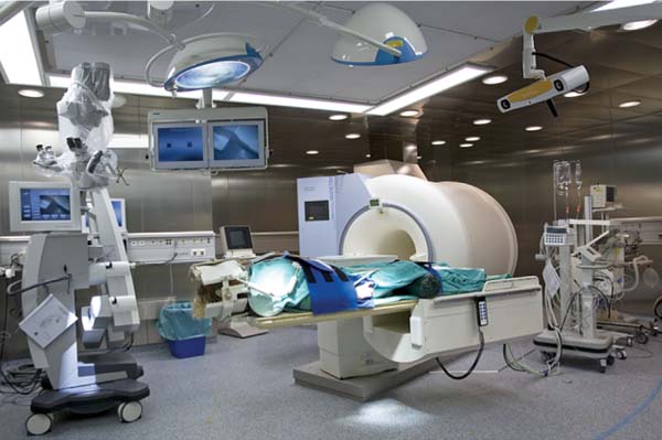
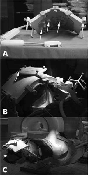
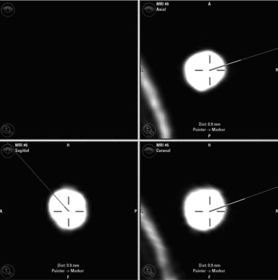
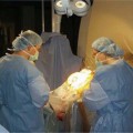
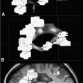
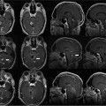
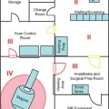
22 Intraoperative imaging has attracted increasing interest in the last decade. The ability to objectively determine the extent of tumor removal during surgery is highly advantageous. If the resection is incomplete, one can attempt to remove the tumor residues that were initially missed during the same operation. In contrast to a subjective estimation by the neurosurgeon, intraoperative imaging allows an objective evaluation of the intraoperative situation, thus acting as quality control during surgery.1–6 In addition to intraoperative imaging, an integral part of our concept of computer-aided surgery is the possibility to apply neuronavigation simultaneously.5,7,8 Neuronavigation allows essentially visualizing the results of pre- and intraoperative imaging in the surgical field, so that the image data provide an immediate feedback. The most important aspect is to prevent increased neurologic deficits despite increased resections that might result from the attempt to remove initially overlooked tumor remnants that are detected by intraoperative imaging. In standard neuronavigation, also known as frameless stereotaxy, the real space of the surgical field is registered to the three-dimensional (3D) image space, which is based on anatomic data only. We prefer the application of microscope-based navigation, where the extent and localization of a tumor is superimposed on the microscope field of view through contours using the heads-up display technology of the modern operating microscopes. Standard neuronavigation based on anatomic information only, which has become a routine tool in many neurosurgical departments, was developed further by the integration of further information from other modalities resulting in the so-called multimodal navigation. A first step in the direction of multimodal navigation was the development of functional navigation, where preoperative data from magnetoencephalography (MEG)9–11 and functional magnetic resonance imaging (fMRI)5,12 defining localizations of cortical eloquent brain areas such as the motor and speech areas in individual patients, were integrated in the navigation set-up. This method of functional neuronavigation allowed for more thorough resection of tumors in risk zones with low morbidity. Integration of diffusion tensor imaging (DTI) data delineating the course of major white matter tracts extended this concept also to subcortical areas,13–16 while the coregistration of positron emission tomography (PET) data and information from MR spectroscopy (MRS) added metabolic information leading to true multimodal navigation.17–22 The neurosurgical operating room should be the integrative place where all patient data can be visualized in a surgeon-friendly fashion. Multimodal navigation – with the visualization of multimodal data on several screens close to the surgical site, as well as the parallel superimposition of the relevant structures visualized by contours in different colors in the microscope field of view – is the main tool to achieve this integration. In contrast to pointer-based navigation, microscope-based navigation provides a more intuitive data visualization directly in the surgical field. Pointer-based systems only delineate the position of an instrument, for example, typically the tip of a pointer in the image space, so that during surgery when navigation information is needed the surgical workflow is interrupted by necessitating that the surgeon look away from the surgical field to a navigation screen. Microscope-based navigation has the advantage of heads-up displays superimposing additional information on the surgical field by color contours or semitransparent 3D objects. Furthermore, the position of an instrument, for example, the autofocus position of the microscope, may be additionally displayed on the navigation screen. However, there is still much room for further enhancements of these display technologies. In most set-ups there is only a 2D visualization, lacking real depth information, which would be possible in a 3D image injection set-up. Also, the real-time rendering of the displayed objects in the current standard commercial systems does not represent what is now possible with near photo-realistic visualizations in other fields of computer graphics. One of the most important aspects in such systems is to avoid a confusion of the neurosurgeon by a potential information overload. Sophisticated systems have to be developed that present the most relevant information at a certain stage of surgery without impeding the surgical workflow and without distracting the neurosurgeon from his main task. What are the navigation concepts in an intraoperative MRI (iMRI) environment? The MRI scanner may serve as a navigational device per se, as is the case with the 0.5 tesla (T) double-doughnut GE (General Electric Medical Systems, Waukesha, WI) scanner. The patient is operated directly in the scanner: the surgical space and imaging space were identical and an instrument in the surgical space could be tracked in image space without much additional effort.1,23,24 Direct navigation in the MRI scanner is often based on realtime imaging, as in so-called prospective stereotaxy, a method for trajectory alignment for placements of catheters or sampling biopsies.25–27 Other systems that integrate iMRI and navigation result in a classical navigation set-up: image space and surgical space are not identical; hence some kind of patient registration has to be applied. Most set-ups implement navigation at the 5 gauss (G) line (Fig. 22.1), so that standard non-MRI-compatible instruments can be used. Ceiling-mounted solutions of the navigation camera and screens5 are an optimal solution in the intraoperative scenario because placing a standard navigation system close to an MRI scanner increases the risk of potential magnetic accidents. To optimize the navigation workflow a close integration of imaging and navigation is necessary. For pre- and intraoperative registration an efficient data transfer between scanner and navigation computers is mandatory; an optimized order of the different imaging sequences allows navigation planning and preparation while scanning is still in process. High navigation accuracy is a prerequisite if the navigation information is to be used at critical steps during the resection of a tumor. Among all errors contributing to the overall navigation accuracy, the initial patient registration process is mostly prone to errors. The most common strategy for patient registration relies on placement of skin-adhesive fiducials, which can be detected in the images, so that their position in virtual and real physical space can be correlated to define the registration coordinate system. Automatic registration set-ups, allowing a user-independent registration of patient space and image space, try to reduce the user-dependent errors.28 Navigation accuracy is influenced by a variety of factors, among them are the so-called application accuracy, factors relating to a unwanted movement of the registration coordinate system (positional shift), and intraoperative events like brain deformation, which is known as brain-shift. The application accuracy is influenced by the quality of imaging, by the technical accuracy of the system itself, and by the quality of patient registration, which defines the process of registering image space and real surgical space.29 Although the spatial distortion of MR images, which is due to gradient field nonlinearities and resonance offsets (chemical shifts and magnetic field inhomogeneities),30 and the technical accuracy of the navigation system are not easily influenced by the user, the patient registration process is very much user-dependent and is influenced by the individual registration strategy and user experience. Fig. 22.1 Operating room set-up at the University Erlangen-Nuremberg with a 1.5 tesla magnetic resonance imaging (MRI) scanner and integrated microscope-based navigation. The navigation camera, as well as the navigation screens are ceiling mounted. The patient’s head is placed at the 5 gauss (G) line, the head is fixed in an 8-channel MR coil/headholder combination with an attached registration matrix for automatic patient registration. Standard patient registration can be achieved in different ways. There are “marker-fit” techniques using either extrinsic markers (so-called fiducials either self-adhesive or implanted in the skull bone) or anatomic landmarks for registration. There are also “surface-fit” techniques using the outer contour of the face and the skull for the referencing process. Several studies31–34 have shown the reliability of these registration methods and rapid progress has been made toward automatic marker detection in image space and semiautomatic registration.35 Nevertheless, the registration process itself still has to be performed manually; therefore it remains time-consuming and prone to error. Automatic registration is based on paired-point registration but it spares the user all the error-prone steps associated with paired-point registration. The main task of automatic registration is to create an unambiguous relationship between the reference array and the acquired images used for navigation. The reference array is an important reflective marker structure rigidly attached to the patient head via the head clamp. It is used as a relative reference for the system to be able to track instruments, even when the stereoscopic camera is moved into a different position. Looking from the mathematical standpoint, the reference array and the volumetric images span two independent coordinate systems. One coordinate system is used to describe the position of tracked instruments in the surgical field or relative to the reference array, the other to render a 3D model of the tracked instrument in the volumetric images, which then is projected on a 2D view on a screen, or superimposed in the operating microscope, allowing the user to navigate on the images. It is generally assumed that these two coordinate systems relate to each other via a rigid transformation matrix, describing the rotation and translation between these coordinate systems – or how to transform one position of the instrument, in the surgical space into a corresponding position in the virtual/image space. To be able to calculate the rotation and translational parameters, at least 3 points in the patient space and corresponding points in the virtual space have to be defined. A paired-point matching algorithm then optimizes the rotation and translational parameters to minimize the root mean square error between these point pairs or even to permute the pairs to achieve an optimal result. An additional indirection for fiducial registration is of importance to implement the automatic registration method. A so-called registration matrix is introduced, which already contains a fixed constellation of fiducials relative to a reflective marker structure, making it possible to use the registration matrix as a tracked instrument (Fig. 22.2A). The registration matrix is attached to the upper part of the head coil, so that the fiducials from the registration matrix are automatically imaged when placed close enough to the patient’s head. Once the scan is completed and the acquired images are transferred to the navigation system, the user only has to adjust the navigation camera so that it can identify the reflective marker structure of the registration matrix and the reference array for a brief moment, so that the navigation system can determine the spatial relation between registration matrix and reference array (Fig. 22.2B). Once the acquisition of the reflective marker structures has been completed, an automatic marker detection algorithm detects the fiducials from the registration matrix in the image dataset. Because the system knows the exact arrangement and position of the fiducials integrated in the registration matrix this information can be used as input for the paired-point matching algorithm. Combining the information about where the registration matrix was in relation to the reference array and how the detected fiducials in the images relate to the fiducials of the registration matrix while also knowing how the fiducials from the registration matrix relate to the spatial position of the matrix itself by the defined construction, a transformation matrix can be calculated directly relating the reference array with the acquired images, so that the relation between image space and physical/surgical space is defined and navigation can be used (Fig. 22.2C). An additional skin fiducial that is not used for the registration process is localized after patient registration to document a target registration error, which is typically in the range between 0.3 and 2.5 mm (Fig. 22.3). Phantom studies resulted in median localization errors between 0.88 and 2.13 mm for the automatic registration approach, which was at least not worse, in most test series even significantly better, than that of the standard registration no matter whether four or seven fiducial markers were used.28 Fig. 22.2 Automatic patient registration. (A) The registration matrix is attached to the upper part of the head coil, the white arrows delineate the fixed integrated markers in the registration matrix, which can be detected automatically. (B) After the head is fixed in the magnetic resonance imaging- (MRI-) compatible headholder the upper part of the MR coil with the registration matrix is attached, reflective markers (white arrow) allow to track the spatial position of the reference matrix, the gray arrow points at the reference array (so-called reference star) that is rigidly attached to the headholder, so that the spatial relation between the head and the reference array is fixed. (C) Overview of patient placement with the head at the 5 G line just after preoperative scanning for initiation of automatic registration. Low postoperative neurologic deficits are mandatory; especially in surgery of high-grade tumors it is of no benefit for the patient to maximize the extent of a resection to potentially increase the survival time by only some weeks, when risking permanent neurologic deficits right after surgery. It is absolutely mandatory to combine the goal of maximum resection with the goal of preservation of function. Intraoperative imaging helps not only to maximize the extent of resection but in combination with functional multimodal navigation also minimization of postoperative neurologic deficits is possible.13,36 With the advances in surgical techniques and perioperative technology, it is now possible to maximally resect malignant intrinsic glial neoplasms, even close to functionally critical areas, without increased morbidity. Studies have demonstrated a survival advantage of these lesions with a resection extent of 98% or greater, particularly in younger patients with good Karnofsky scores.37 Fig. 22.3 A skin fiducial, which is not used for patient registration, allows to document the target registration error; after automatic registration the tip of a pointer is placed in the dip of the fiducial and its position is documented with the navigation system, which calculates the offset.
Equipment Integration: Neuronavigation
Implementation of Navigation in the Surgical Workflow
Automatic Registration
Multimodal Navigation
Related posts:
Stay updated, free articles. Join our Telegram channel

Full access? Get Clinical Tree


