10-s acquisition
20-s acquisition
Low dose
High dose
High dose
Rotation times (s)
10
10
20
Rotation angle (°)
219
219
219
Increment
0.8
0.8
0.4
No. of frames
273
273
538
CTDIvol (mGy)
12.3
35.1
59.5
DAP (μGy m2)
856
2,382
4,289
Effective dose (mSv)
E dip method
0.4
1.1
1.9
DAP method
0.24
0.67
1.2
Clinical Applications
Evaluation of Atherosclerotic Intracranial Arterial Stenosis
Accurate assessment of atherosclerotic major intracranial stenosis in terms of severity and stenosis length is important for early detection and its proper treatment. The requirements of the ideal noninvasive test for measuring intracranial stenosis is as follows: (1) good depiction of lesions including stenosis severity and length, and occlusion level; (2) a shorter canning time; (3) good delineation of calcification in the arterial wall; and (4) subsequent endovascular treatment after symptomatic stenosis in emergent situation. IV FDCT has shown to have a good depiction of lesion location and collateral circulation in the single acquisition. Jeon et al. [13] reported that IV FDCT showed a sensitivity of 97.6 %, specificity of 96.9 %, and negative predictive value (NPV) of 96.9 % for identifying stenosis ≥50 % with DSA as the reference value. For detecting stenosis ≥70 %, in particular, a sensitivity of 91.9 %, specificity of 98.2 %, and NPV of 97.4 were estimated. Good correlation of the measuring stenosis severity between the two tests was observed according to direction (horizontal segments vs. vertical segments) and circulation (anterior circulation vs. posterior circulation) [13]. Length discrepancy (IV FDCT–DSA, in millimeters) was more pronounced in higher stenosis, but the result was not statistically significant [13]. Such a discrepancy could be originated from the difference in hemodynamics and attenuation of the contrast agents. Assessment of stenosis length after the point of maximal narrowing could be influenced by the flow velocity and stenosis severity [13, 14]. In addition, diluted contrast agent of the IV FDCT may fill the vessel lumen more uniformly than DSA due to their similarity of attenuation values for contrast agents and blood [15].
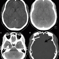
IV FDCT can allow information on various vascular territories and collateral flow in a single acquisition [16]. Additionally, clear visualization of the calcification of the arterial wall, which can be of limited value in the DSA images, can be obtained (Fig. 1a, b). Because calcification of the arterial wall can be related to incomplete stent deploy [17, 18], an accurate detection of calcification is necessary for selecting treatment methods [19]. Blanc et al. [16] and Riedel et al. [20] reported that IV FDCT shows good depiction of occlusion level, clot length, collateral vessels, and patency of anterior and posterior communicating arteries in a single acquisition (Fig. 1c, d, f). Relative complete filling of the collateral vessels and reconstructed images in various planes in IV FDCT allows better depiction of the arteries beyond the occlusion level, clot length, and stenosis nature than DSA [16], which leads to decreased amount of contrast and radiation dose [14]. IV FDCT can also be conducted to exclude intracranial hemorrhage in patients suspected of acute cerebral infarction. Because attenuation difference is 10 HU in IV FDCT [7, 21], it can clearly depict hemorrhage lesion before intra-arterial thrombolysis [22]. Because acute ischemic stroke has a 6-h therapeutic time window for intra-arterial thrombolysis [23], timely assessment of the stenosis nature and subsequent treatment is important to obtain good neurologic outcomes [8, 24]. Therefore, in particular, IV FDCT can be useful for early diagnosis of acute cerebral infarct and its subsequent treatment.
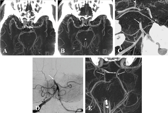
Fig. 1
IV FDCT MIP axial images show a clear depiction of the vascular lumen from circumferential calcification (arrows) without superimposition of bone (arrowheads) (a and b) [13]. IV FDCT MPR coronal image (c) reveals the occlusion of the middle third of the basilar artery (arrow) which is consistent with that of DSA (d). The right posterior communicating artery (arrowhead) and both P1 are well visualized. IV FDCT MPR axial image shows clear depiction of the both posterior communicating artery (arrows) [16]
Role of IV FDCT in Endovascular Procedure
Advances in microcatheter and balloon technologies have increased an incidence of endovascular treatment and its success rate in patients with symptomatic intracranial stenosis. However, procedural complications such as hemorrhage, vessel dissection, and infarction can occur. In particular, symptomatic intracranial hemorrhage has been reported with a range from 1.1 to 15.4 % [22, 23, 25] and can lead to neurological deficit. Accordingly, early detection is important to avoid poor neurologic outcome during the periprocedural period. In such circumstances, IV FDCT can allow real-time monitor on complications in the same angiosuite without patient transfer [14, 26]. Karman et al. [14] reported that IV FDCT was feasible to detect or exclude suspected procedure-related complications. White et al. [12] reported that IV FDCT was a substantial factor in decision making for 40.9 % of patients during the peri-endovascular period. In their study, IV FDCT provided clear depiction of the extensive leakage of the contrast media through perforation site by microcatheter, enlarged ventricle size, and presence of hemorrhage. Accordingly, prompt detection of adverse events and subsequent appropriate management can be achieved on the same angiotable.
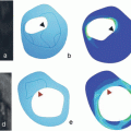
IV FDCT can also be used as a follow-up tool for stent-implanted arteries. The use of intracranial stent placement for atherosclerotic stenosis has been increasingly reported [27, 28]. Intracranial stents require low-profile system and adequate radial strength with high flexibility [18]. Accordingly, high spatial resolution and a lower susceptibility artifact of the radiologic test as well as sufficient radiopacity of the stents are necessary to obtain information on the stent position and arterial wall clearly in the follow-up test. IV FDCT allows stent position and cross-sectional images within the stent with a good spatial resolution of approximately 0.1 mm. Spatial resolution can be influenced by pixel binning as well as focal spot size and reconstruction methods [10]. In general pixel binning, combination of a cluster of pixels into a single pixel can decrease spatial resolution. Kalender et al. [9] demonstrated better spatial resolution of the IV FDCT compared to multi-slice spiral CT (MSCT) by comparing modulation transfer time (MTF) and visual estimate of bar pattern phantom according to different pixel binning [18]. Ebrahimi et al. [5] investigated stent conformity in curved vascular models among studies of IV FDCT, DSA, and digital radiography. In their study, IV FDCT provided more clear visualization of stent deployment and adverse stent mechanics such as increased cell opening and strut prolapse than digital radiography or DSA (Fig. 2). Nevertheless, IV FDCT can offer increased noise level and decreased low-contrast resolution than MSCT. Kalender et al. [9] showed the different ability to detect low-contrast details according to noise and dose. Reconstructed images from high spatial resolution can make images with high noise, which can decrease low-contrast detectability. When increasing dose, improvement of noise level and low-contrast detectability can be observed. Accordingly, technical advances in enhancing low-contrast resolution are necessary in IV FDCT.
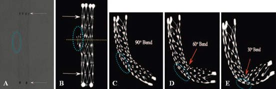
Fig. 2
Comparison of stent conformity in curved vascular models among IV FDCT and digital radiography (DR) in an in vitro study. Although the proximal and distal marker of the stent (a, arrows), Neuroform 2, is well visualized by DR images, stent cells and struts are poorly described. IV FDCT MIP image shows clear depiction of the stent architecture such as struts and connectors (arrows). Cross-sectional image (yellow-dotted line) can provide the protrusion of the stent through a hole (dotted blue circle) (b) In simulated cases over an 8-mm hole (dotted blue circle), flattering of the Enterprise stent as an increase in bending is clearly shown (c–e)
Consensus over a contrast protocol in stent implantation in human intracranial arteries remains undetermined. Patel et al. [3] optimized a contrast protocol in stent-implanted swine model. The protocol was as follows: (1) 20 % of iodinated contrast (iopamidol 51 %, Isovue; 250 mg/mL iodine concentration) in normal saline; (2) 2-s time delay; and (3) velocity of 3.0 mL/s for 23 s at the common carotid artery in the anterior circulation or 2.0 mL/s for 23 s at the vertebral artery in the posterior circulation. Nevertheless, optimal contrast attenuation in stented arterial segment in human has not been clearly established.
An Estimate of Cerebral Perfusion by IV FDCT
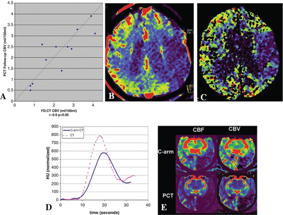
Beyond identification of anatomical information on the intracranial stenosis, identification of brain perfusion abnormalities is also important to select revascularization methods. Recently, the feasibility of IV FDCT in measuring cerebral blood volume (CBV) or cerebral blood flow (CBF) has been studied. Struffert et al. [4] compared CBV lesion between IV FDCT and MSCT in patients with acute MCA occlusions. Because FDCT CBV map can be calculated only under the steady-state condition of contrast medium in the brain parenchyma, “bolus watching” method was used during the acquisition [4, 29]. A high correlation between abnormal CBV lesion on IV FDCT and stroke volume on follow-up MSCT was observed in the oligemic areas in the initial image (Fig. 3a–c). In addition, IV FDCT and perfusion CT showed comparable absolute CBV. Royalty et al. [30] compared IV FDCT and perfusion CT in measuring CBV and CBF in canine stroke model. The perfusion acquisition protocol of IV FDCT which was used was as follows: (1) seven 200° rotations over 2.8 s with a 1.5-s pause between rotations; (2) 133 projections at about 60 projections per second during rotation; (3) 70 kVp and 1.2 μGy/frame dose level in each projection; and (4) mainly 5-s X-ray time delay [30]. High levels of interobserver agreement for detecting ischemic lesion and perfusion mismatch between CBV and CBF in IV FDCT were observed. Nevertheless, technical limitations of IV FDCT include lower temporal resolution than conventional perfusion CT and low-contrast resolution. The lower temporal resolution of the IV FDCT attributes to the broader time attenuation curve with lower peak, in particular voxels that are arteries. Accordingly, overestimated CBV and CBF can be achieved (Fig. 3d, e) [30]. The lower temporal resolution could be improved by increasing rotation speed of C-arm or a steady state of contrast enhancement within the brain parenchyma [30, 31]. A protocol for the fastest commercial C-arm rotation is over 6 s of a temporal sampling rate [30]. Although Royalty et al. [30] showed an increased temporal sampling rate of 4.3 s, consistent overestimation of the CBV and CBF still remains. Accordingly, further study on the temporal sampling rate-lowering algorithm is necessary to obtain perfusion parameters which are compatible perfusion CT. A steady state of contrast enhancement can be obtained by increase in duration of contrast injection [31]. However, optimal contrast dose and injection route have not been well established in IV FDCT. In addition, consensus on the X-ray time delay remains undetermined. As a result, future work on the optimal value of contrast dose, injection route, and X-ray time delay should be studied together.