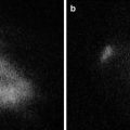
Fig. 11.1
Fluobeam® medical device; central processing unit and the camera head
Fluobeam® Medical Device
The Fluobeam® medical device allows visualizing, on a computer screen, the flow, the distribution and/or the accumulation of near-infrared fluorescent agents such as ICG, injected to patient before and/or during surgery for various indications such as:
Intraoperative visualization and detection of primary liver tumors and/or hepatic metastases located less than 0.5 cm from liver surface.
Intraoperative better visualization of tumor margin on the raw liver surface during parenchyma transaction.
Intraoperative identification of bile ducts.
Intraoperative assessment of liver vascularization.
Fluobeam® is composed of (Fig. 11.1):
1.
Optical head, which is composed of the camera and the optical elements such as fibers, filters, lens, and diffusers. The optical head is also the place where light emission occurs: laser and LEDs (Light Emitting Diodes).
2.
Control box including all the elements to control, monitor, and supply power to the optical head.
3.
Cable including electrical wires and optical fibers. Cable is mechanically linked to the optical head, and can be plugged/unplugged to/from the electrical case through a dedicated connector.
4.
Power supply and RJ 45 cable.
5.
Imaging software (Fluosoft™) (Fig. 11.2 ), which allows real-time visualization of the fluorescent images acquired by the optical head. It also contains the control commands of the Fluobeam® and allows the recording of images, sequence of images and videos.
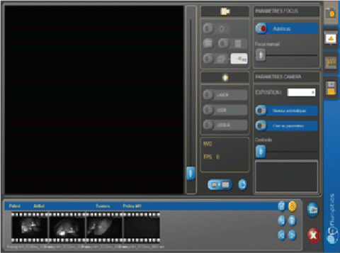

Fig. 11.2
Fluosoft™ screen shot demonstrating the various functional commands
Fluobeam® is a class IIa CE marked medical device. It allows the visualization of fluorescent moiety with a maximum emission between 760 and 850 nm for an excitation wavelength of 750 nm. Fluobeam® includes a class 1 laser source which is safe under all conditions of normal use. The laser light is conveyed from the control box to the optical head via an optical fiber. Two laser beams are emitted from the optical head shedding light on an elliptic area of 15 cm × 10 cm at a distance of 20 cm from the optical head.
Fluobeam® includes an illumination ring based on white and near-infrared LEDs in order to provide a natural white illumination during the surgery. A zoom of 10× can be directly driven by the user via two push-buttons located on the front side of the optical head, which allow changing of the field of view from a maximum of 20 cm × 15 cm to a minimum of 2 cm × 1.5 cm. For distance ranging from 20 to 50 cm between the optical head and the examined area, the camera autofocus ensures a precise focusing and leads to sharp image. Depending on the intensity of the fluorescence signal, the exposure time of the camera can be adjusted from 1 ms to 1 s which allows the acquisition of videos with a frequency ranging from 25 images per second to 1 image per second.
One of the advantages of Fluobeam® is the software accompanying the devices that allow to optimize the exposure according to the intensity of fluorescence. These settings were automatic or manual and allowed to improve largely the quality of images that could be recorded on the software as images and movies. A subsequent analysis of the intensity of fluorescence in specific area of the image according to time could be made on the same software.
As for the other devices, the main drawback of Fluobeam® device was the relatively large size of the camera head that renders the exposure of the upper part of the liver surface difficult.
Our Experience with Hepatic Malignant Tumors
The small number of patients that we had analyzed to date with Fluobeam® is not sufficient to conclude concerning the accuracy of this device to detect underestimated superficial lesion. We presented in this chapter some images that we had obtained with Fluobeam® in some specific situation to demonstrate the quality of images obtainable by this device.
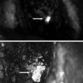
Currently, we aim at increasing the specificity of this technique especially in patients with abnormal liver function and/or cirrhosis where we observed more lesions were falsely interpreted as potentially malignant compared to patients without cirrhosis (Fig. 11.3).
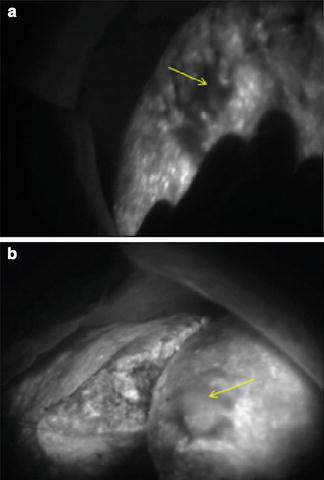

Fig. 11.3
(a) Undifferentiated HCC (arrow) on a cirrhotic liver background. (b) Moderately differentiated HCC (arrow) over cirrhotic liver
Hepatocellular Cancers
Fluorescence intensity correlated well with the differentiation of the HCC when analyzed by fluorescence microscopy [6]. In live fluorescence-guided surgery, we were able to notice the difference in the HCC differentiation based on the brightness (Fig. 11.3). Although this was done in retrospect, after the histopathologic examination of the specimens, it demonstrates that real-time fluorescence could be useful in tumor grading. We are currently working on stratification and quantification of this relation.
Due to its relatively uncommon incidence, there is no specific report on the use of indocyanine green during surgery for fibrolamellar carcinoma. In our experience, fibrolamellar carcinoma captures well the indocyanine green and subsequently emits strong fluorescent signal (Fig. 11.4).
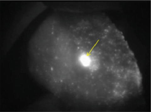

Fig. 11.4
Fibrolamellar HCC (arrow) on a non-cirrhotic background
Cholangiocarcinoma
The same concept is applicable for cholangiocarcinoma. The tumor retains the indocyanine green and emits strong bright fluorescence on exposure to the near infrared light. Real-time determination of the free resection margin is of paramount importance to minimize the recurrence. As shown in Fig. 11.5, fluorescence imaging was a useful tool in ascertaining the tumor safety margin.
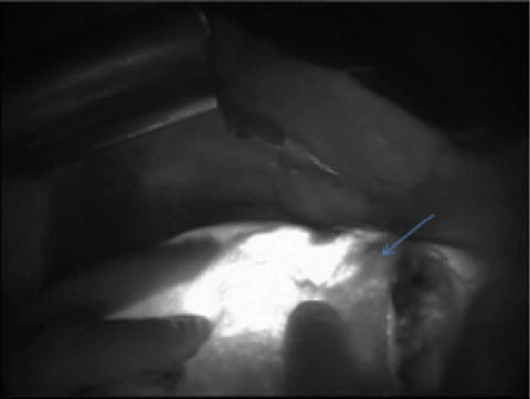


Fig. 11.5
Bright cholangiocarcinoma with surrounding safety margin (arrow) during anatomical resection
Stay updated, free articles. Join our Telegram channel

Full access? Get Clinical Tree


