Introduction
Long considered to be a vital diagnostic tool utilized exclusively within the realm of cardiology, transesophageal echocardiography (TEE) is being used safely and effectively within the perioperative, critical care, and emergency room settings. Of particular importance is the ability to diagnose a vast array of diverse pathologies causing hemodynamic instability. In this capacity, a focused TEE examination has been proven to serve as an important adjunct to the history and physical examination to aid in the clinical decision-making process and to help guide treatment strategies.
Comparing TEE to TTE
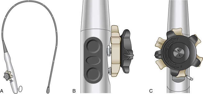
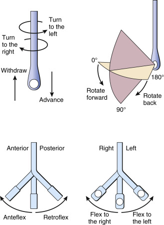
The transducers utilized in transthoracic echocardiography (TTE) are typically single-plane phased array probes, requiring the sonographer to physically manipulate the probe to move from one view to the next. On the other hand, most TEE probes, and for the purposes of the discussion in this chapter, are multiplane phased array probes. Several thousand piezoelectric crystal elements are assembled in a matrix configuration ( Fig. 11.1 ) and mounted to the distal tip of an endoscope. This arrangement allows a linear scan line to be created that can be electronically rotated from 0 toward 180 degrees using two buttons on the handle of the ultrasound probe ( Fig. 11.2 ). As such, multiple views are able to be created without any physical probe manipulation. Rotating the scan line (also called the omniplane angle ) in the direction of 180 degrees is termed rotating forward , whereas rotating back to 0 degrees is termed rotating backward . Physical probe manipulation can be performed by turning the large control wheel on the handle to anteflex (anteriorly) or retroflex (posteriorly) the probe. Furthermore, the tip of the probe can be flexed left or right by rotating the smaller control wheel. The shaft of the probe can be advanced, withdrawn, turned clockwise to image right-sided structures, or turned counterclockwise to image left-sided structures ( Fig. 11.3 ).

The transducers used in TEE can generally operate at a higher frequency, as high as 8 MHz in some cases, compared with the typical 1 to 5 MHz of TTE probes. Although this leads to less depth of penetration, the overall resolution and image quality are better than TTE. Additionally, the TEE probe sits in the esophagus in close proximity to the heart, unlike in TTE, where the ultrasound waves must travel through multiple layers of tissue, ribs, and potentially aerated lung before reaching the heart.
Given the relative position of the esophagus to the heart, specific structures are better visualized with TEE compared with TTE. Anterior structures tend to be imaged better using TTE, and posterior structures tend to be better imaged using TEE. One caveat, however, is that the left atrium sits next to the TEE transducer. Because the ultrasound beam of a phased array probe starts at a narrower origin and fans out (just as it appears on the screen of the machine), the entire left atrium can generally not be visualized using TEE. However, the mitral valve (MV), aortic valve (AV), and left atrial appendage (LAA) are visualized well. TTE, on the other hand, provides better imaging of the left ventricular (LV) apex and more optimal Doppler alignment through both the aortic and tricuspid valves, allowing for more accurate calculations of cardiac output and right ventricular (RV) systolic pressures, respectively.
A standard nomenclature is used to name all of the TEE views that varies slightly from the TTE nomenclature. The first portion of the naming format refers to the transducer location (upper esophageal, midesophageal, transgastric). This is followed by the primary anatomic structure of interest and then the imaging plane (short axis versus long axis). For instance, the midesophageal aortic valve short axis (TEE) corresponds to the parasternal aortic valve short axis (TTE).
Although TTE remains a powerful diagnostic tool in the assessment of critically ill patients, it has several limitations. Unlike TEE, TTE is dependent on patient positioning and body habitus and is difficult in patients with emphysematous lung disease. Imaging can also be difficult in patients with dressings or chest tubes in place and also suboptimal in mechanically ventilated patients in the intensive care unit (ICU) compared with TEE. Conducting a TTE examination in patients undergoing cardiopulmonary resuscitation (CPR) is technically challenging. However, due to TEE’s semiinvasive nature, it is generally not tolerated as well in awake patients. TEE remains an overall safe imaging modality, with an overall complication rate of 0.2% to 1.2% and a risk of injury leading to death of less than 0.01%.
Careful consideration must be given to the associated risks of TEE ( Table 11.1 ), as well as the appropriate indications and contraindications to the placement of a TEE probe ( Table 11.2 ). A TEE examination should only be performed in patients in whom a transthoracic examination is thought to be suboptimal and in whom the benefits are deemed to outweigh the overall risks of probe placement.
| Lip laceration and bruising |
| Dental damage |
| Hoarseness/odynophagia/dysphagia |
| Bleeding (minor and major) |
| Cardiac dysrhythmias |
| Tracheal extubation or entry into trachea |
| Vocal cord damage |
| Laryngospasm/bronchospasm |
| Visceral perforation |
| Death |
| Absolute | Relative |
|---|---|
| Patient refusal | Hiatal hernia |
| History of esophagectomy | Cervical spine instability |
| Significant esophageal pathology/injury | Esophageal varices |
|
|
|
|
|
|
|
|
|
|
|
|
| |
| |
| Recent upper gastrointestinal surgery within the last 6 months |
The TEE Examination
Multiple medical societies encourage the use of ultrasound and have created various position papers regarding both the training requirements and educational curricula needed to achieve proficiency. Moreover, many of these societies advocate for focused or goal-directed examination protocols to help physicians make time-sensitive, potentially lifesaving clinical decisions.
Focused, or “rescue,” TEE exists for this purpose, allowing physicians to use an abbreviated examination sequence at the bedside in patients suffering from sudden, unexplained hemodynamic instability. In these situations, a comprehensive examination may waste valuable time and delay treatment. Although multiple protocols have been described, an 11-view examination sequence will be described in this chapter ( Fig. 11.4 ). Please keep in mind that not all 11 views will always be necessary or be easily obtained. Focused TEE emphasizes speed and efficiency by using a qualitative and dichotomous approach. Usually, a diagnosis can be elucidated with a select number of views. One must keep in mind that due to anatomic variations from patient to patient and the potential for pathology to distort cardiac anatomy, the described approaches for obtaining the views as they relate to both imaging depth and omniplane angle can vary considerably.


Great care must be given during both probe placement and manipulation. Before placement, the oral cavity should be inspected for signs of obvious dental damage or previous injury. A dental guard should always be used to minimize the risk of dental trauma and probe damage. The probe control lock should always be in a neutral position and never engaged during probe placement or manipulation, although slight anteflexion of the tip with the control wheel may be helpful during insertion. A generous amount of lubrication should be applied to the probe before placement in the oropharynx. The probe should never be forced if met with resistance. Gently lifting the mandible anteriorly may be helpful in placement, as is occasionally either neck flexion or extension. Direct laryngoscopy may also be used. The exam should be performed in a manner that minimizes overall probe manipulation, including minimizing the number of times the probe is advanced and withdrawn.
When performing an examination, a few basic rules optimize image quality. First, the focal zone should be set at or slightly above the anatomic structure of interest. The resolution will be the highest in this zone. Furthermore, the depth should also consider the structure of interest so as to further enhance resolution and detail. The greater the depth, the lower the overall resolution. To image deeper structures, the frequency may need to be decreased. Finally, the gain is the amplification of the ultrasound signal and should be set in a manner to improve contrast between fluid and tissues.
TEE Views
Midesophageal Four-Chamber View (ME 4C) ( Fig. 11.5,  )
)
The TEE probe should be advanced into the esophagus approximately 30 to 40 cm. The omniplane angle should be set to between 0 and 20 degrees. Often, some slight retroflexion of the probe may help to develop the view to open all four chambers. This is due to the LV apex being positioned slightly inferiorly and laterally relative to the base of the heart. In the adult chest, the imaging depth should initially be set to about 16 cm to ensure the entirety of the heart is visualized. If the AV and left ventricular outflow tract (LVOT) are still visible (informally called a five-chamber view ), the probe should be advanced slightly into the esophagus until the LVOT disappears, only the four chambers are visible, and the annulus of the tricuspid valve is maximized.
The right heart will appear on the left side of the screen, and the left heart will appear on the right. Both the atria will be at the top of the screen closest to the TEE probe separated by the interatrial septum. The ventricles reside on the bottom of the screen separated by the interventricular septum. The tricuspid and MVs are visible on the left and right, respectively. Furthermore, the anterolateral and inferoseptal walls of the left ventricle appear in this view.
Midesophageal Two-Chamber View (ME 2C) ( Fig. 11.6,  )
)
![]()
With only minor physical manipulation of the probe, the omniplane angle should be rotated forward to between 80 and 100 degrees. The left atrium (top) and left ventricle (bottom) will both be visible. The anterior and inferior walls of the left ventricle will appear on the right and left of the screen, respectively. The left atrial appendage will be visible and can be assessed for clots.
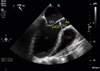
Midesophageal Long-Axis View (ME LAX) ( Fig. 11.7,  )
)
The omniplane angle is further rotated from the ME 2C view to between 120 and 160 degrees. Again, both the left atrium and left ventricle are visible. The MV resides on the left side of the screen, and the long axis of the AV can be visualized on the right side of the screen at the distal end of the LVOT as it opens to the proximal ascending aorta. The anteroseptal wall separates the left ventricle from the RV outflow tract. The inferolateral wall of the left ventricle is visible on the left side of the screen.
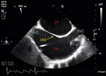
Midesophageal Bicaval View (ME Bicaval) ( Fig. 11.8,  )
)
From the ME LAX view, the shaft of the probe should be turned clockwise and the omniplane angle rotated backward to between 80 and 110 degrees. The depth should be decreased to maximize visualization of all the relevant structures.
The superior vena cava (SVC) will appear on the right side of the screen, and the inferior vena cava (IVC) will appear on the left. The interatrial septum can be visualized separating the left atrium (top of screen) from the right atrium (bottom of screen) and consists of a thinner region termed the fossa ovalis flanked by thicker limbus regions both anteriorly and inferiorly. Assessments for the presence of a patent foramen ovale or interatrial shunt should be made utilizing color flow Doppler (CFD) with the Nyquist limit decreased to detect lower-velocity blood. Occasionally, a eustachian valve and crista terminalis are visible at the inlets of the IVC and SVC, respectively. These normal anatomic variants are embryologic remnants and appear as a fluttering flap, not to be confused with a vegetation.
Midesophageal Right Ventricular Inflow–Outflow View (ME RV Inflow–Outflow) ( Fig. 11.9,  )
)
Without moving the probe, the omniplane angle should be decreased even farther to approximately 50 and 90 degrees. The valve on the left is the tricuspid valve as blood inflows into the right ventricle. Toward the right of the screen, the long axis of the pulmonic valve appears and serves as the outflow of blood from the right ventricle, hence the name of this view. Although, the aortic valve short axis often can be visualized in this view, emphasis should be placed on identifying both the pulmonic and tricuspid valves. The left atrium appears as the chamber closest to the probe near the top of the screen.
Midesophageal Aortic Valve Short-Axis View (ME AV SAX) ( Fig. 11.10,  )
)
Decreasing the omniplane angle from the RV inflow–outflow view to between 30 and 60 degrees will help to visualize all three leaflets of the AV in short axis. Typically, this involves only a slight decrease in the omniplane angle, if at all. Not uncommonly, all three valves can be seen in the same view. Furthermore, the same chambers as in the ME RV inflow–outflow view are also visible.
Midesophageal Ascending Aortic Short-Axis View (ME Asc Ao SAX) ( Fig. 11.11,  )
)
From the ME 4C view, the probe should be withdrawn until a “five-chamber view” develops. The LVOT and the AV should be centered. The probe should be withdrawn slightly farther (approximately 30–35 cm), and with some slight anteflexion, the view will develop.
The vascular structure in the middle of the view is the short axis of the aorta and may appear pulsatile. To the left of the aorta is the short axis of the SVC. To the right of the aorta in this view, the main pulmonary artery (PA) can be visualized as it divides into the left and right branches. The right PA branches off the main and progresses to the left side of the screen, whereas the left PA is often difficult to visualize due to the interposition of the left mainstem bronchus between the left PA and the esophagus.
Midesophageal Ascending Aortic Long-Axis View (ME Asc Ao LAX) ( Fig. 11.12,  )
)
This view is obtained by simply rotating the omniplane angle forward to approximately 100 to 150 degrees from the ascending aortic short-axis view. In the near field at the top of the screen, the short axis of the right PA becomes visible, and distal to that resides the long axis of the aorta.
Transgastric Midpapillary Short-Axis View (TG Midpap SAX) ( Fig. 11.13,  )
)
From the ME 4C view, the probe should be advanced to an approximate depth of 40 to 45 centimeters and then slightly anteflexed at an omniplane angle of 0 to 20 degrees until both papillary muscles are visible and the circular symmetry of the left ventricle is optimized. The imaging depth should be decreased to maximize the size of the left ventricle.
Both the left and right ventricles are depicted in this view. Furthermore, the transgastric short axis is the only view that allows for assessment of LV segmental wall motion as it correlates to the distribution of all three coronary arteries in a single plane. Both the posteromedial and anterolateral papillary muscles are visible.
Descending Aortic Short-Axis View (Desc Ao SAX) ( Fig. 11.14,  )
)
Withdraw the probe back to the ME 4C view and rotate the shaft of the probe 180 degrees until the descending aorta comes into view. The depth should be decreased to approximately 6 to 8 cm to maximize the size of the aorta. The probe should be advanced and withdrawn to scan as much of the descending aorta as possible starting from the proximal descending arch. The short axis of the aorta is visualized and should appear circular.
Descending Aortic Long-Axis View (Desc Ao LAX) (see Fig. 11.14,  )
)
From the short axis of the aorta, the omniplane angle should be increased to approximately 90 to 110 degrees. The aorta is now visualized in its long axis, with blood flowing proximally from the right side of the screen distally to the left.
Related posts:
Stay updated, free articles. Join our Telegram channel

Full access? Get Clinical Tree


