 he complex anatomy of the hand and wrist presents interesting imaging challenges regardless of the modality selected. Both detection and classification of pathology can be difficult. This chapter will focus on pre- and postoperative imaging of trauma, arthroplasty, and other common orthopaedic procedures used in the hand and wrist. Again, emphasis will be placed on procedures requiring orthopaedic implants or fixation devices.
 Trauma
Fractures and dislocations of the hand and wrist occur commonly. Common injury patterns, classifications, and methods of fixation will be discussed by anatomic region. Imaging of postoperative complications will be included with each major section.
Distal Radius and Ulna
Fractures of the distal radius, with or without ulnar involvement, account for 15% to 25% of fractures in adults. There is a bimodal distribution with injuries due to high-velocity trauma in children and young adults and fractures due to minor falls in the elderly. The likelihood of sustaining a distal radial fracture is 6% in patients older than 80 years and 9% for white females older than 90 years. The mechanism of injury is a fall on the outstretched hand with varying degrees of osseous and soft tissue injury. Tears of the triangular fibrocartilage complex, scapholunate, and lunotriquetral ligaments are not uncommon. These injuries appear to be most common with radial fractures involving the lunate fossa. The importance of the radiolunate articulation has been emphasized by using a three-column approach. The lateral column is the osseous buttress of the wrist and includes the intracapsular ligaments. The intermediate column includes the radiolunate fossa and articulation that functions primarily for axial loading. The medial column functions for rotation and secondary load transmission. This column includes the triangular fibrocartilage complex (see Fig. 13-1).
Classification
There are numerous eponyms for fractures of the distal radius and ulna (see Chapter 2). Currently, these terms are less frequently used for describing fractures. It is more important to describe the relationships, degree and direction of displacement, and degree of comminution of the injury. Suspected soft tissue injuries should also be noted.
There have been numerous classification systems developed for the distal radius and ulna including the Mayo, Melone, Frykman, and AO (Arbeitsgemeinshaft fur Osteosynthesefragen) classifications. Classification systems should suggest treatment approaches, indicate prognosis, and demonstrate intra- and interobserver reliability. The Frykman classification is based on the extent of articular involvement and presence or absence of an ulnar styloid fracture (see Fig. 13-2). This classification system does not address the direction and extent of displacement. The Mayo, Melone, and Association for Study of Internal Fixation (ASIF) systems consider the degree of comminution, degree of displacement, articular involvement, and mechanism of injury. The AO system considers extra-articular fractures. Type I, simple or partial articular type II, and complex or comminuted fractures are considered complete articular or type III. There are numerous subcategories for each type. The Mayo system is based on the degree of displacement and reducibility. For example, extra-articular fractures are subdivided into undisplaced (type I) and displaced (type II). Type III fractures are intra-articular and undisplaced and type IV are displaced articular fractures. Type IV is further subdivided based on being stable and reducible (type IVA), reducible and unstable (type IVB), and irreducible (type IVC). Studies using any of the above-mentioned systems fail to demonstrate highly reproducible inter- and intraobserver agreement for any of the classification methods discussed earlier. A more practical or absence of an ulnar styloid fracture (see Fig. 13-2). This classification system does not address the direction and extent of displacement. The Mayo, Melone, and Association for Study of Internal Fixation (ASIF) systems consider the degree of comminution, degree of displacement, articular involvement, and mechanism of injury. The AO system considers extra-articular fractures. Type I, simple or partial articular type II, and complex or comminuted fractures are considered complete articular or type III. There are numerous subcategories for each type. The Mayo system is based on the degree of displacement and reducibility. For example, extra-articular fractures are subdivided into undisplaced (type I) and displaced (type II). Type III fractures are intra-articular and undisplaced and type IV are displaced articular fractures. Type IV is further subdivided based on being stable and reducible (type IVA), reducible and unstable (type IVB), and irreducible (type IVC). Studies using any of the above-mentioned systems fail to demonstrate highly reproducible inter- and intraobserver agreement for any of the classification methods discussed earlier. A more practical
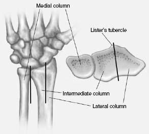
 Fig. 13-1 Illustration of the three columns of the wrist. The lateral column includes the lateral portion of the distal radius with the intracapsular ligaments; the intermediate column includes the medial portion of the radius, lunate fossa, and radiolunate articulation. This serves primarily for axial loading. The medial column includes the ulna and triangular fibrocartilage complex.
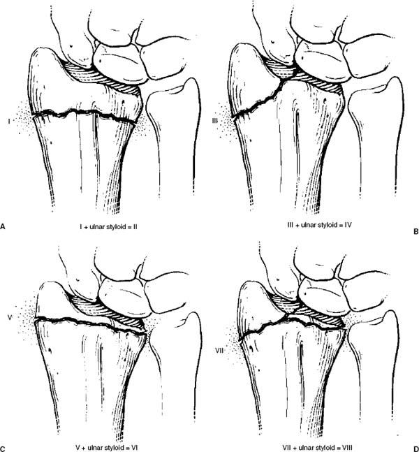
 Fig. 13-2 Illustrations of the Frykman classification. A: Type I—extra-articular without ulnar styloid involvement, type II—extra-articular with ulnar styloid fracture. B: Type III—intra-articular involving the radiocarpal joint without an ulnar styloid fracture, type IV—same as type III with an ulnar styloid fracture. C: Type V—fracture involving the distal radioulnar joint without an ulnar styloid fracture, type VI—same as type V with an ulnar styloid fracture. D: Type VII—distal radial fracture involving both the radiocarpal and distal radiounlar joint without an ulnar styloid fracture, type VIII—same as type VII, but with an ulnar styloid fracture.
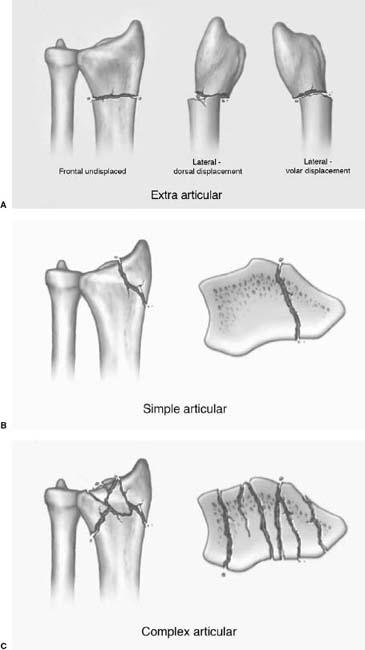
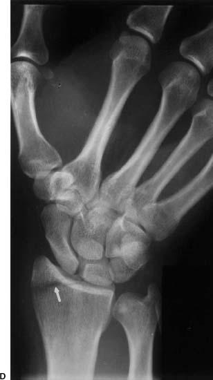
 Fig. 13-3 A: Illustration of extra-articular distal radial fractures. B: Illustration of simple articular distal radial fractures. C: Illustration of complex articular distal radial fractures. D: Radiograph of a simple articular fracture (arrow) entering the margin of the lunate fossa.
SUGGESTED READING
Andersen DJ, Blair WF, Steyers CM, et al. Classification of distal radius fractures: An analysis of interobserver reliability and intraobserver reproducibility. J Hand Surg [Br]. 1996;21A:574–582.
Barrett JA, Baron JA, Karagas MR, et al. Fracture risk in the US. Medicare population. J Clin Epidemiol. 1999;52:555–558.
Chen NC, Jupiter JB. Management of distal radial fractures. J Bone Joint Surg. 2007;89A:2051–2062.
Cooney WP III. Fractures of the distal radius. A modern treatment-based classification. Orthop Clin North Am. 1993; 24:211–216.
Flinkkila T, Nikkola-Sihto A, Kaarela O, et al. Poor interob-server reliability of AO classification of fractures of the distal radius. J Bone Joint Surg. 1998;80B:670–672.
Frykman G. Fractures of the distal radius including sequelae–shoulder hand-finger syndrome, disturbance of the distal radioulnar joint and impairment of nerve function. Acta Orthop Scand Suppl. 1967;108:1–55.
Geissler WB, Freeland AE, Savoie FJ, et al. Intracarpal soft-tissue lesions associated with fracture of the distal end of the radius. J Bone Joint Surg. 1996;78A:357–365.
Imaging Techniques
Radiographic views of the wrist following trauma should include posteroanterior (PA), lateral, and at least one (we typically perform both) oblique. The scaphoid view is also frequently added. The forearm and elbow may also need to be imaged in patients with more proximal shaft fractures. Subtle fractures may be easily overlooked, especially in children and the elderly. Therefore, the pronator fat stripe should be carefully evaluated. If this structure is displaced or obliterated, it may be the only sign of a subtle distal radial fracture or physeal injury in a child (see Fig. 13-5). The navicular fat stripe will be reviewed in the carpal fracture section.
Additional studies may be required. Magnetic resonance imaging (MRI) may be useful in symptomatic patients without radiographic evidence of fractures (Fig. 13-5). MRI is also useful to evaluate associated or isolated soft tissue injuries in patients with wrist trauma. Once identified, computed tomography (CT) is often performed to properly classify the injury and provide a map for treatment planning (Fig. 13-4). CT images are reformatted in the coronal and sagittal planes. Three-dimensional reconstructions can also be obtained.
SUGGESTED READING
Berquist TH, Trigg SD. Hand and wrist. In: Berquist TH, ed. Imaging atlas of orthopaedic appliances and prostheses. New York: Raven Press; 1995:831–921.
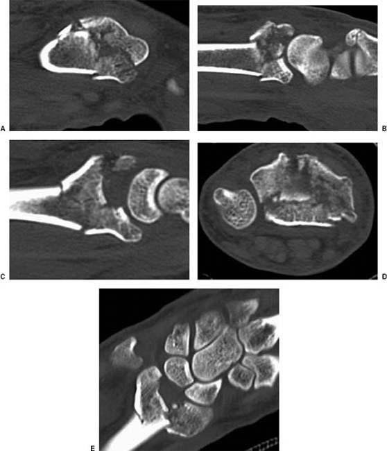
 Fig. 13-4 Complete (complex) articular fracture. Sagittal (A to C), axial (D), and coronal (E) CT images of a complex distal radial fracture with dorsal impaction or the distal fragment (B), fragmentation of the radial styloid (A) and marked articular step off (C and E) of the lateral and intermediate columns. There is comminution of the metaphysis and articular surface (D).
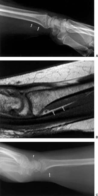
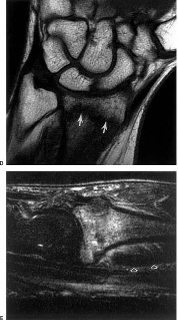
 Fig. 13-5 Pronator fat stripe. Lateral radiograph (A) and sagittal T1-weighted magnetic resonance (MR) image (B) demonstrating the normal position and appearance of the pronator fat stripe (arrows). Lateral radiograph (C) in a patient with an occult distal radial fracture and a dorsal triquetral fracture (arrowhead). Note the displaced and partially obliterated fat stripe (arrow). Coronal T1- (D) and sagittal T2- (E) weighted images demonstrate the fracture (arrows) and displaced fat stripe (open arrows).
Treatment Options
Treatment options include closed reduction with cast immobilization, external, and internal fixation. Treatment goals include anatomic reduction, maintenance of radial length, and neutral ulnar length.
Closed Reduction and Immobilization
Undisplaced extra-articular or simple articular fractures can be managedwithclosedreductionandcast immobilization. Circular or bivalved casts (see Chapter 2) may lead to compartment syndrome. Therefore, padded splints with the wrist in slight palmar flexion and neutral rotation are most often used. Displaced extra-articular or simple articular fractures can also be managed with closed reduction, but require fracture manipulation to achieve anatomic reduction. This may require finger traction before application of sugar-tong splints. Surgical intervention is indicated if reduction cannot be maintained as demonstrated on follow-upradiographs. Inthissetting, percutaneouspinning with K-wires or plate and screw fixation may be required.
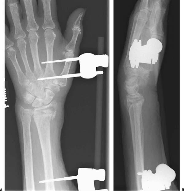
 Fig. 13-6 Anteroposterior (AP) (A) and lateral (B) radiographs following external fixation of a complex distal radial fracture using a static fixation system with a radiolucent bar. The radial length is maintained, although there is slight reduction in the radial inclination angle.
External Fixation
External fixation is useful for unstable distal radial fractures and provides a less invasive option to internal fixation. Static and dynamic devices along with radiolucent external fixators are available (see Figs. 13-6 and 13-7). Selection of the external fixation device is based on the perceived difficulty in maintaining radial length and alignment as well as surgical preference.
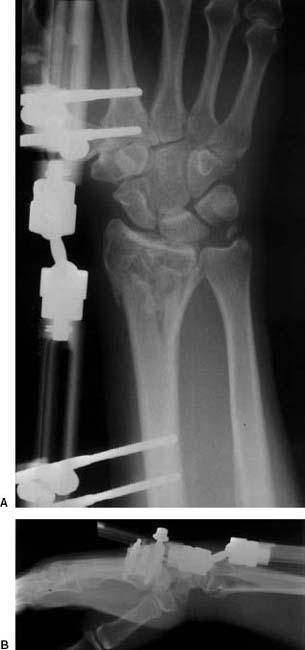
 Fig. 13-7 Anteroposterior (AP) (A) and lateral (B) radiographs following external fixation with a four-pin Orthofix external fixation system that allows motion at the wrist. The complex distal radial fracture is reduced with length and alignment maintained. There is also an ulnar styloid fracture.
Initial fracture reduction can be accomplished with finger traction using 10 to 15 lb of weight. External fixation is then applied using four to five pins. Dynamic devices allow wrist motion, which should be started when tolerated to reduce stiffness and adhesive capsulitis following treatment.
Internal Fixation
Internal fixation with open reduction is indicated for unstable fractures (does not adequately reduce with closed methods or reduction cannot be maintained). As noted earlier, percutaneous pins can be used for extra-articular fractures with dorsal or volar displacement and simple articular fractures (see Fig. 13-8). Volar plate and screw fixation is used when there is comminution of the metaphysis or there are multiple articular fragments (see Fig. 13-9).
Depressed central fragments in the lunate or scaphoid fossa should be evaluated with CT and repositioned using bone graft to reestablish the articular surface. Stabilization can be established with percutaneous pins or volar plate and screws.
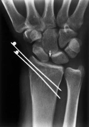
 Fig. 13-8 Posteroanterior (PA) radiograph following percutaneous pinning of an undisplaced radial styloid fracture with two K-wires. Note the widened scapholunate space (arrow) due to an associated scapholunate ligament tear. The fracture line had entered the lunate fossa.
SUGGESTED READING
Chen NC, Jupiter JB. Management of distal radial fractures. J Bone Joint Surg. 2007;89A:2051–2062.
Chung KC, Watt AJ, Kotsis SV, et al. Treatment of unstable distal radial fractures with the volar locking plate system. J Bone Joint Surg. 2006;88A:2687–2694.
Thomas S, John C, Hohnny TP. Intra-articular distal radial fractures–external fixation or conventional closed reduction? J Orthop. 2007;4:39–43.
Werber KD, Raeder F, Brauer RB, et al. External fixation of distal radial fractures: Four compared to five pins: A randomized prospective study. J Bone Joint Surg. 2003;85A:660– 666.
Imaging of Distal Radial Fracture Complications
Postoperative radiographs should be consistently evaluated with certain features in mind. Radial length, alignment, articular deformity, radial inclination angle, palmar tilt, and findings that suggest associated ligament injury should all be assessed on each follow-up radiograph.
Radial length should be within 1 mm or the ulnar length, although some accept up to 5 mm of radial shortening (see Fig. 13-10). The normal radial inclination angle is 22 to 25 degrees. Following distal radial fracture, the fragments should be reduced to result in a radial inclination angle of 15 degrees or more (see Fig. 13-11). On lateral radiographs, the normal distal radial articular surface has a volar or palmar tilt of 11 to 12 degrees. Depending on the degree of dorsal or volar impaction, this angle can be increased, neutral, or reversed. Dorsal angulation of up to 15 degrees and increased volar tilt of 20 degrees are considered acceptable reductions (Fig. 13-11B). Articular deformity or step off should be <2 mm. This can be difficult to evaluate on radiographs. CT with reformatting (Fig. 13-4) is optimal for evaluation of articular fragments and involvement of three columns (Fig. 13-1).
Radial height and shift should also be evaluated (see Figs. 13-12 and 13-13). Radial height is measured by a line perpendicular to the radial shaft and a parallel line along the radial styloid tip. This is normally 13.5 mm ± 3.8 mm (Fig. 13-12).
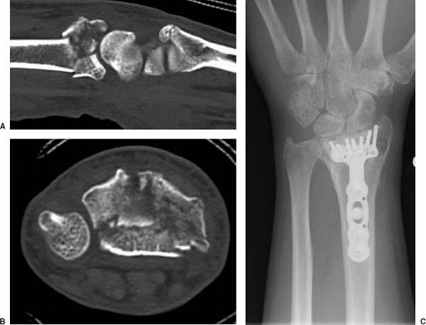
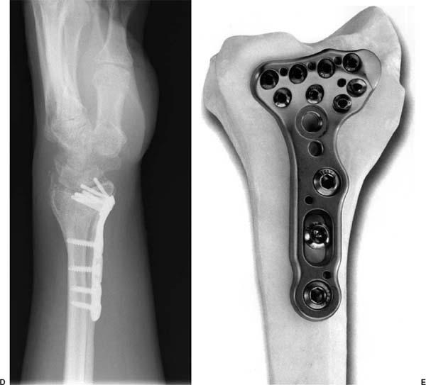
 Fig. 13-9 Sagittal (A) and axial (B) computed tomographic (CT) images of a complex distal radial fracture involving the radiocarpal and distal radioulnar joints. Anteroposterior (AP) (C) and lateral (D) radiographs following reduction with a volar plate and screws. E: Acumed Acu-Loc targeted distal radius plate with locking screws. (Courtesy of Acumed, Hillsboro, Oregon.)
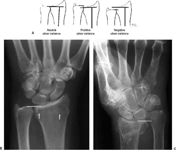
 Fig. 13-10 Radial length. A: Illustration of neutral, positive, and negative ulnar variance. B: Posteroanterior (PA) radiograph demonstrating a distal radial fracture (arrows) entering the distal radioulnar joint. Radial length (line) is maintained. C: Complex impacted distal radial fracture with marked loss of radial length (line) and >1 cm of ulnar positive variance.
The carpal bones should be in normal position with parallel joint surfaces that normally measure approximately 2 mm. Asymmetry or widening, specifically at the scapholunate or lunotriquetral articulations, suggests associated ligament injury (Fig. 13-8). Fractures of the ulnar styloid or medial column and significant differences in radial and unlar length (Fig. 13-1) may be associated with triangular fibrocartilage complex injuries (Figs. 13-7 and 13-10C).
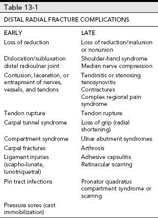
Complications related to distal radial fractures may be related to the injury or treatment method selected. Complications are common and classically divided into early and late complications (see Table 13-1).
Imaging of complications related to position of fragments (Figs.13-10 to 13-13), loss of reduction, malunion, nonunion, and shortening (see Fig. 13-14) can be accomplished with serial PA and lateral radiographs. Nonunion can be more effectively evaluated with CT. CT can demonstrate the extent of callus, bone loss, and fragment position more easily than radiographs (see Fig. 13-15). Implant failure can also be effectively evaluated radiographically and with CT (see Figs. 13-15 and 13-16).
Osseous complications vary with treatment approaches. For example, the mean loss of radial length in patients with Colles’ type fractures was 3 mm in patients treated with closed reduction. Dorsal angulation increased by 7 degrees in patients treated with closed reduction. Rigid fixation with external or internal fixation provides more stability.
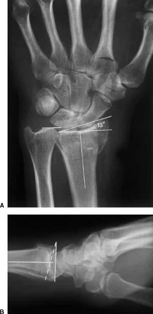
 Fig. 13-11 Radial inclination angle. A: Posteroanterior (PA) radiograph demonstrating an intra-articular fracture with loss of length (ulnar line) and a reduced radial inclination angle of 13 degrees (angle formed by a line perpendicular to the radial shaft and a line from the styloid tip to the ulnar margin of the distal radius, normal 22 to 25 degrees, acceptable ≥15 degrees). B: Lateral radiograph demonstrating dorsal impaction of the radius with neutral palmar tilt. Broken line demonstrates the normal palmar (volar) tilt of 11 to 12 degrees.
External fixation is associated with certain complications. Although often minor, complications occur in up to 67% of patients. Pin tract infections occur commonly (12% to 38%) but can usually be treated with local wound care and antibiotics. Sixteen percent of patients develop carpal instability and pin loosening occurs in 8% of patients. Imaging of these complications can usually be accomplished with serial radiographs. MRI or CT may be required to evaluate deep infection.
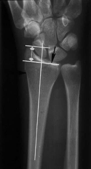
 Fig. 13-12 Radial height. Posteroanterior (PA) radiograph demonstrating a simple articular fracture (arrows) with measurement of radial height. A line is drawn perpendicular to the radial shaft at the ulnar articular margin of the distal radius. A second line is drawn parallel to this. The distance between the lines (double arrow) is the radial height (normal 13.5 mm ± 3.8 mm or 9.7 to 17.3 mm).
Volar plate fixation (Figs. 13-9 and 13-16) may cause irritation of the flexor carpi radialis and flexor pollicis longus. Dorsal screw prominence may result in extensor tendon irritation and retinacular scarring.
Ligament injuries are frequently associated with distal radial fractures. The scapholunate and lunotriquetral ligaments are most commonly involved. Scapholunate ligament injuries have been reported in up to 54% of patients with distal radial fractures. Widening of the intercarpal joint spaces may be evident on radiographs (Fig. 13-8). More subtle injuries can be evaluated with motion studies using fluoroscopy and conventional or MR arthrography.
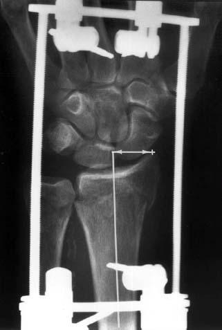
 Fig. 13-13 Radial shift. This measures the offset of radial fragments from the central axis. Posteroanterior (PA) radiograph with external fixation of a distal radial fracture. The distance of a line down the center of the radial shaft to the styloid tip in this case measures the degree of shift. Displacement of >1 mm is considered significant.
Neural injury may be related to the treatment approach or injury. Compressive neuropathies occur in the median nerve in 4%, and ulnar and radial neuropathies in <1% of patients treated with closed reduction. Transient paresthesias occur in 2% to 25% of patients. Soft tissue injuries (tendon rupture, tendon entrapment, compartment syndrome, and neural injuries) are optimally imaged with MRI. However, MRI may not be useful depending on the type and location of implants in relation to the structures in question. Subluxation of the distal radioulnar joint can be evaluated with CT in the axial plane with the wrist in neutral, pronation, and supination.
Complex regional pain syndrome or reflex sympathetic dystrophy can be evaluated with radiographs or three-phase bone scans (see Fig. 13-17). Arthrosis commonly occurs following distal radial fracture, especially those involving the joints. Radiocarpal and intercarpal changes can be easily followed with serial radiographs (see Fig. 13-18).
SUGGESTED READING
Anderson JT, Lucas GL, Buhr BR. Complications of treating distal radius fractures with external fixation: A community experience. Iowa Orthop J. 2004;24:53–59.
Chen NC, Jupiter HB. Management of distal radial fractures. J Bone Joint Surg. 2007;89A:2051–2062.
Forward DP, Lindau TR, Melsom DS. Intercarpal ligament injuries associated with fractures of the distal part of the radius. J Bone Joint Surg. 2007;89A:2334–2340.
Hove LM. Nerve entrapment and reflex sympathetic dystrophy after fractures of the distal radius. Scand J Plast Reconstr Surg Hand Surg. 1995;29:53–58.
Hove LM, Soheim E, Skjeie R, et al. Prediction of displacement of Colles’ fracture. J Hand Surg [Br]. 1994;19B:731– 736.
Mann FA, Wilson AJ, Gilula LA. Radiographic evaluation of the wrist. What the surgeon want to know? Radiology 1992; 184:15–24.
Werber KD, Raeder F, Brauer RB, et al. External fixation of distal radial fractures: Four compared to five pins: A randomized study. J Bone Joint Surg. 2003;85A:660–666.
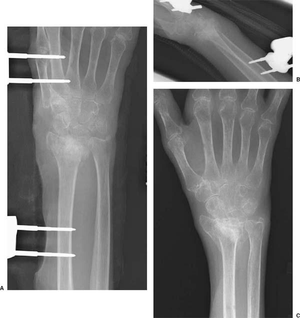
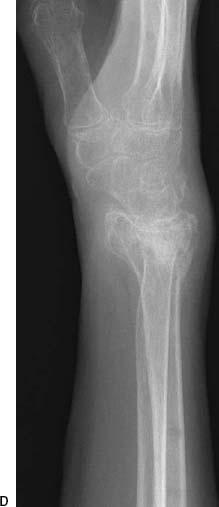
 Fig. 13-14 Complex distal radial fracture with radial shortening treated with external fixation. Posteroanterior (PA) (A) and lateral (B) radiographs following external fixation demonstrate radial shortening with loss of radial inclination and height, carpal collapse, ulnar lunate abutment, and neutral palmar (volar) tilt. Radiographs following healing (C and D) demonstrate stable position with radiocarpal arthrosis and osteopenia.
Carpal Fracture/Dislocations
The osseous and soft tissue anatomy of the wrist is complex. A complete discussion is beyond the scope of this text. However, key anatomic features are important to review. There are eight carpal bones (scaphoid, lunate, triquetrum, pisiform, trapezium, trapezoid, capitate, and hamate) that form two carpal rows. The scaphoid links the proximal and distal carpal rows. The proximal carpal row articulates with the radius and the second carpal row and the distal row articulates with the metacarpal bases. The joint spaces should be parallel and approximately 2 mm in width. Lines along the carpal bones on frontal radiographs (see Fig. 13-19) should form smooth arcs. With ligament injury and dislocation the arcs are interrupted. The carpal height can also be evaluated on the PA radiograph using two methods (see Fig. 13-20). The scapholunate relationship should be evaluated on lateral images (see Fig. 13-21). The neural and tendon relationships of the wrist are illustrated in Figure 13-22 and the complex ligament and triangular fibrocartilage complex anatomy in Figures 13-23 and 13-24.
Scaphoid Fractures
Scaphoid fractures are the most common carpal fracture accounting for 70% of carpal fractures and more than half of carpal injuries. Associated osseous and soft tissue injuries are not uncommon. Associated fractures occur in 5% to 12% of patients involving the radial styloid, triquetrum, capitate, and trans-scaphoid perilunate dislocations. Associated fractures of the radial head have been reported in 6% of patients. The mechanism of injury is a fall on the outstretched hand. Most injuries are sports related or occur with motor vehicle accidents. Patients present with pain and swelling. There is tenderness over the snuff box on the radial side of the wrist. Fractures can occur at any age, but males aged 20 to 30 years are affected most commonly.
Scaphoid fractures may involve the proximal, mid or distal scaphoid, or the tubercle (see Fig. 13-25). Most fractures (70%) involve the waist, 10% to 20% the distal pole, 5% to 10% the proximal pole, and 5% involve the tuberosity. Two classification systems are used for scaphoid fractures. The Russe classification is based on the orientation of the fracture line (see Fig. 13-26). The vertical oblique fracture is most susceptible to shearing forces, but accounts for only 5% of scaphoid fractures. Horizontal oblique fractures are subjected to compressive forces across the fracture site and transverse fractures have combined shearing and compressive forces.
The Herbert classification is based on stability and prognosis for delayed or nonunion. Fractures of the tubercle (type A1—Fig. 13-25, number 1) and incomplete fractures of the waist (type A2) are stable injuries. Type B includes acute unstable fractures. Type B1 is a distal oblique fracture, type B2 a fracture through the waist (Fig. 13-25, number 4), type B3 is a proximal pole fracture (Fig. 13-25, number 5), and type B4 injuries are trans-scaphoid perilunate fracture dislocations.
SUGGESTED READING
Haisman JM, Rohde RS, Weiland AJ. Acute fractures of the scaphoid. J Bone Joint Surg. 2006;88A:2750–2758.
Herbert TJ. Fractured scaphoid. St. Louis: Quality Medical Publishers; 1990.
Nattass GR, King JW, McMurtry RY, et al. An alternative method for determination of carpal height ratio. J Bone Joint Surg. 1994;76A:88–94.
Russe O. Fracture of the carpal navicular. Diagnosis, non-operative treatment and operative treatment. J Bone Joint Surg. 1960;42A:759–768.
Imaging Techniques
Detection of scaphoid fractures may be accomplished with routine radiographs of the wrist. A special scaphoid view is typically added to the standard PA, lateral, and oblique images described in the prior section. The soft tissues and fat planes should be carefully evaluated along with the features described earlier. Specifically, the navicular fat stripe is a useful tool for detection of subtle scaphoid fractures. This fat plane lies between the radial collateral ligament and the tendon sheaths of the abductor pollicis longus and extensor pollicis brevis. Although the fat stripe is not consistently seen on radiographs in children, it is evident in 96% of adults. The fat plane is displaced or obliterated in 88% of radial-sided wrist fractures and 87% of scaphoid fractures (see Fig. 13-27).
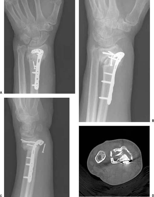
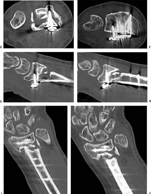
 Fig. 13-15 Posteroanterior (PA) (A), lateral oblique (B), and oblique (C) radiographs of a distal radial fracture treated with volar plate and screw fixation. The fracture line is sclerotic indicating delayed union or nonunion and there is pull-out of one of the screws, which lies in the region of the flexor tendons and median nerve. Computed tomographic (CT) images in the axial plane (D to F) demonstrate bone loss with sclerosis of the main fragments and pull-out of the plate on the ulnar side. Sagittal (G and H) and coronal (I and J) reformatted images more clearly demonstrate the bone loss with a fragment in the area of nonunion and sclerosis at the margins of the main fragments.
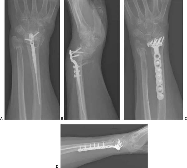
 Fig. 13-16 Failed fixation. Posteroanterior (PA) (A) and lateral (B) radiographs demonstrating internal fixation of a distal radius fracture. There is also a distal ulnar fracture. The screws have pulled out of the distal radial fragment, which is now displaced volarly. PA (C) and lateral (D) radiographs following revision using a volar locking plate and screws. The distal radial fragment is realigned.
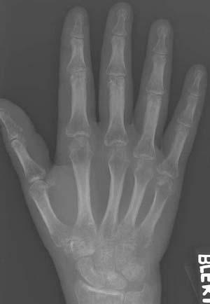
 Fig. 13-17 Complex regional pain syndrome. Radiograph demonstrates marked osteopenia in the wrist and aggressive osteopenia about the articulations of the hand.
Subtle fractures may go undetected. When radiographs are negative or the fat stripe is not clearly seen and when there is clinical suspicion for fracture, MRI can be obtained. CT is also more sensitive and specific compared to radiographs for detection of carpal fractures. In addition, CT is often performed to permit more accurate treatment planning (see Fig. 13-28).
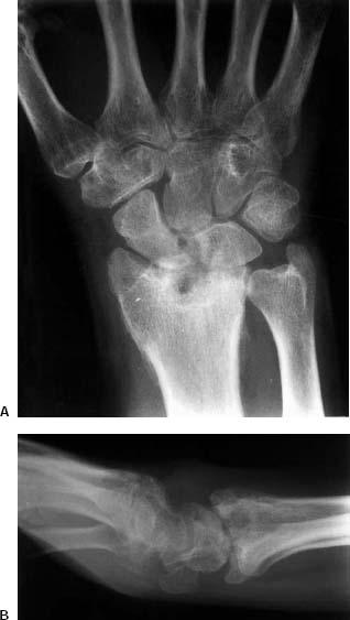
 Fig. 13-18 Post-traumatic arthrosis. Posteroanterior (PA) (A) and lateral (B) radiographs following healing of an intraarticular fracture of the distal radius. There is advanced radiocarpal arthrosis with articular irregularity and joint space narrowing. There is also intracarpal arthrosis.
SUGGESTED READING
Berquist TH, Trigg SD. Hand and wrist. In: Berquist TH, ed. Imaging atlas of orthopaedic appliances and prostheses. New York: Raven Press; 1995:831–921.
Terry DW, Ramin JE. The navicular fat stripe. A useful roentgen feature in evaluating wrist trauma. AJR Am J Roentgenol. 1975;124:25.
You JS, Chung SP, Chung HS, et al. The usefulness of CT for patients with carpal bone fractures in the emergency department. Emerg Med J. 2007;24:248–250.
Treatment Options
Fracture management depends on patient factors and comorbidities, the type of fracture, and associated injuries. Fractures of the distal pole or tuberosity (Fig. 13-25, number 1) generally heal well, are likely related to vascularity, and can be managed with closed reduction and cast immobilization (long-arm or short-thumb spica) for 4 to 6 weeks.
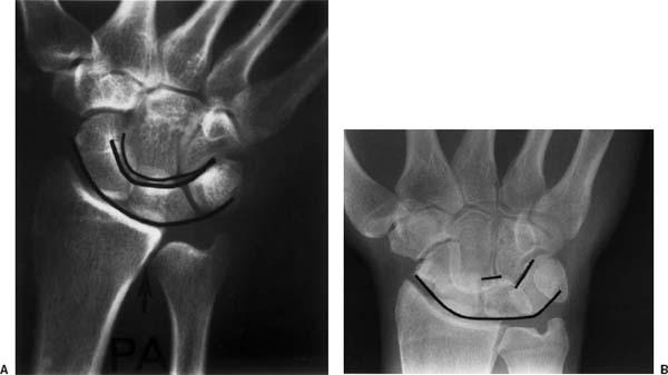
 Fig. 13-19 Carpal relationships on the posteroanterior (PA) radiograph. A: Normal radiograph with smooth arcs (curved lines) formed by the articular surfaces of the carpal bones. B: The arcs are interrupted in this patient with a trans-scaphoid perilunate dislocation.
Fractures of the waist may be managed with closed reduction and cast immobilization or internal fixation. CT (Fig. 13-28) is useful to evaluate displacement. Reformated coronal and sagittal images are obtained along the axis of the scaphoid. The fracture is displaced or unstable if there is >1 mm of cortical step off, angulation, or associated ligament injury. When the scapholunate angle exceeds 60 degrees and the radiolunate angle exceeds 15 degrees the fracture is considered displaced. The interscaphoid angle should not exceed 35 degrees (Fig. 13-28). Internal fixation using a Herbert screw or fully threaded Acutrak screw is used in this setting (see Fig. 13-29). Internal fixation provides the additional advantage in that the patient can begin motion earlier and the fracture is rigidly fixed so that loss of alignment is unlikely.
Fractures of the proximal pole should be treated with internal fixation. The approach and fixation used varies with the size of the proximal fragment. In recent years, percutaneous pinning over a guidewire placed down the axis of the scaphoid has become more popular. When combined with arthroscopy, the fracture site can be directly visualized during the procedure.
SUGGESTED READING
Cooney WP, Dobyns JH, Linscheid RL. Fractures of the scaphoid: A rational approach to management. Clin Orthop. 1980;149:90–97.
Haisman JM, Rohde RS, Weiland AJ. Acute fractures of the scaphoid. J Bone Joint Surg. 2006;88A:2750–2758.
Imaging of Complications
Scaphoid fractures present significant problems in management. Following diagnosis, imaging is important to assure that position is maintained and healing occurs. Delayed union and nonunion are common. Delayed union (failure to heal in 4 months) is even more common than nonunion and is evident in up to 30% of waist and proximal pole fractures. The incidence of nonunion is reported to range from 5% to 25%. Undisplaced fractures treated with cast immobilization heal in 90% of cases. The incidence of nonunion is higher with displaced fractures. Imaging is most easily accomplished with serial radiographs (see Fig. 13-30). However, CT is often required regardless of the treatment approach to evaluate position and healing more effectively (Fig. 13-29). MRI demonstrates low-intensity fracture margins with fluid signal intensity between the fragments when fractures are ununited (see Fig. 13-31). MRI is optimal for evaluation in patients treated with closed reduction. In the presence of nonunion, internal repair with bone grafting may be required.
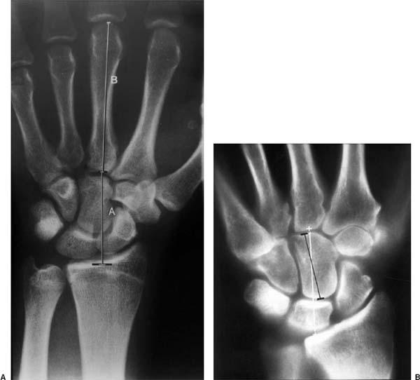
 Fig. 13-20 Carpal height. A: Carpal height ratio comparing the carpal height (A) to the length of the third metacarpal (B) (normal 0.54 ± 0.3). B: Modified method measured along the axis of the third metacarpal. The carpal height (white line) divided by the capitate height (black line) should be 1.57 ± 0.06.
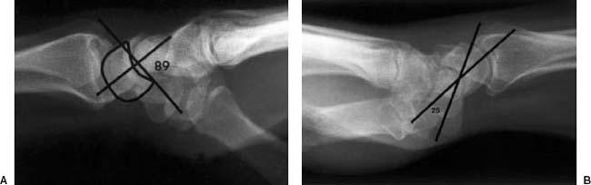
 Fig. 13-21 Scapholunate angle. The normal scapholunate angle is 47 degrees with the wrist in neutral position. This can decrease to 30 degrees or increase to 60 degrees with radial or ulnar deviation. A: With dorsal intercalated segment instability (DISI) the angle increases (89 degrees in this case) and the lunate looks dorsally. B: With volar intercalated segment instability (VISI) the angle is decreased (25 degrees in this case) and the lunate is tilted in a palmar or volar direction.
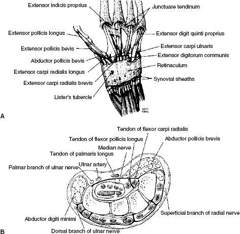
 Fig. 13-22 A: Illustration of the six dorsal extensor compartments and tendons. B: Illustration of the flexor tendons, carpal tunnel, and median and ulnar nerves. (From Berquist TH. MRI of the hand and wrist. Philadelphia: Lippincott Williams & Wilkins; 2003.)
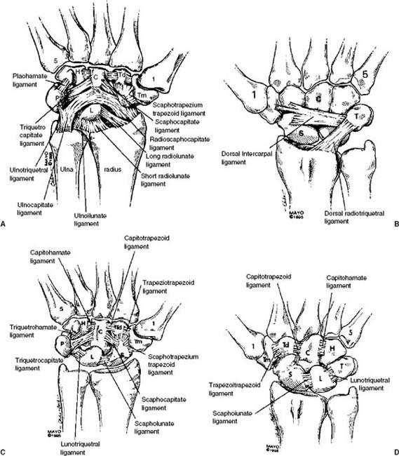
 Fig. 13-23 Ligament anatomy of the wrist. Illustrations of the palmar (A) and dorsal (B) ligaments of the wrist. Illustrations of the palmar (C) and dorsal (D) intercarpal ligaments. C—capitate, H—hamate, L—lunate, P—pisiform, S—scaphoid, T—triquetrum, Td—trapezoid, Tm—trapezium, 1—first metacarpal, 5—fifth metacarpal. (From Berger RA. L—ligament anatomy. In: Cooney WP III, Linscheid RL, Dobyns JH, eds. The wrist: diagnosis and operative treatment. St. Louis: Mosby; 1998:72–105.)
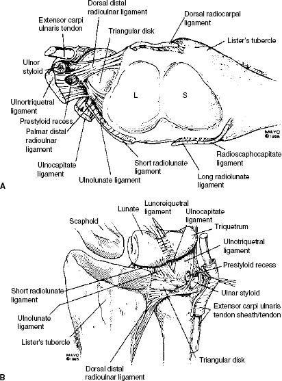
 Fig. 13-24 A: Illustration of the distal radius (L—lunate fossa, S—scaphoid fossa), ligament attachments, and triangular fibro-cartilage complex with radioulnar ligaments. B: Illustration of the ulnocarpal ligament complex and triangular fibrocartilage complex seen in the dorsal form. Note the relationship of the prestyloid recess and ulnotriquetral ligaments. (From Berger RA. L—ligament anatomy. In: Cooney WP III, Linscheid RL, Dobyns JH, eds. The wrist: diagnosis and operative treatment. St. Louis: Mosby; 1998:72–105.)
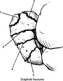
 Fig. 13-25 Illustration of the locations for fractures of the scaphoid. 1—tubercle, 2—distal articular surface, 3—distal third, 4—waist, 5—proximal pole.
Avascular necrosis is reported to occur in 15% to 30% of scaphoid fractures, occurring most commonly with proximal pole fractures. Radiographs may demonstrate sclerosis and fragmentation of the proximal fragment (see Fig. 13-32). Both CT and MRI are more sensitive and can make the diagnosis earlier. However, over time it has become evident that neither modality is perfect. Signs suggesting avascular necrosis vary with the time between the injury and imaging. Abnormal signal intensity on MRI (see Fig. 13-33) and increased attenuation on CT images (see Fig. 13-34) may be reversible and do not always indicate impending osteonecrosis. Dynamic contrast-enhanced MR images with fat-suppressed T1-weighted sequences provide more effective evaluation of flow. This enhances the sensitivity and specificity for blood flow to the scaphoid and areas of necrosis.
Post-traumatic arthropathy is not uncommon, especially with nonunion or scaphoid fractures with associated osseous or soft tissue injury. Over time, carpal instability may also occur. In patients with nonunion, this is termed scaphoid nonunion advanced collapse (SNAC). Serial radiographs are adequate for evaluation of joint and osseous changes. If fusion or surgical intervention may be indicated, MRI or CT are useful for more complete evaluation of cartilage and soft tissues. MR arthrography is optimal for evaluation of associated ligament and triangular fibrocartilage complex (TFCC) injuries.
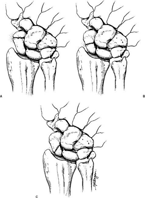
 Fig. 13-26 Russe classification of scapoid fractures. A: Horizontal oblique. B: Transverse. C: Vertical oblique.
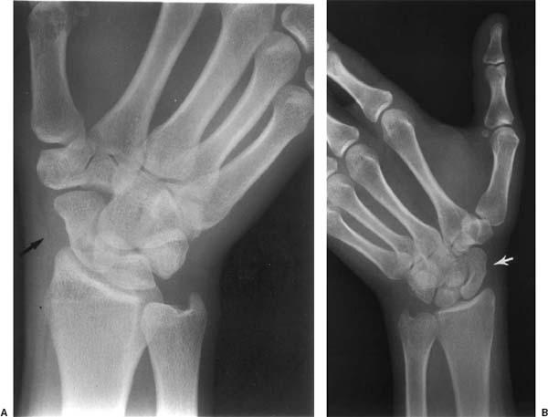
 Fig. 13-27 Navicular fat stripe. A: Scaphoid view demonstrating a normal fat stripe (arrow). B: Occult scaphoid fracture with no visible fat stripe (arrow).
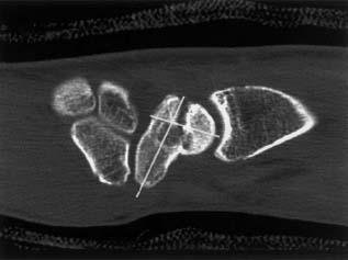
 Fig. 13-28 Sagittal computed tomographic (CT) image demonstrating a scaphoid fracture with “humpback” deformity (lines).
SUGGESTED READING
Cerezal L, Abascal F, Canga A. Usefulness of gadolinium-enhanced MR imaging in the evaluation of vascularity of scaphoid nonunions. AJR Am J Roentgenol. 2000;174:141–149.
Haisman JM, Rohde RS, Weiland AJ. Acute fractures of the scaphoid. J Bone Joint Surg. 2006;88A:2750–2758.
Mack GR, Bosse MJ, Gelberman RH, et al. The natural history of scaphoid non-union. J Bone Joint Surg. 1984;66A: 504–509.
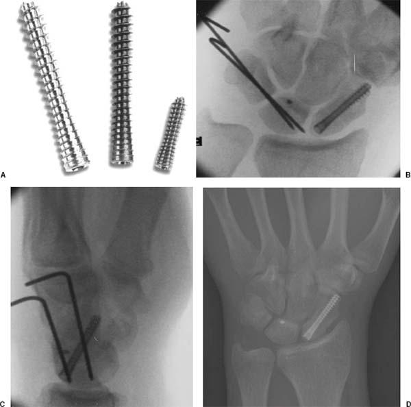
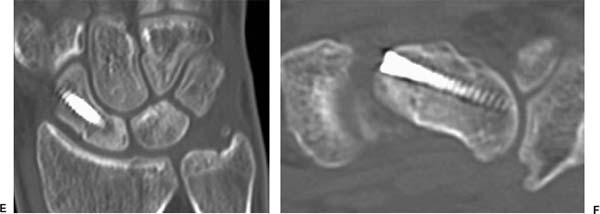
 Fig. 13-29 Scaphoid fracture with Acutrak screw fixation. A: Acutrak screws. (Courtesy of Acumed, Hillsboro, Oregon.) Posteroanterior (PA) (B) and lateral (C) radiographs taken during screw fixation and ligament repair with K-wire fixation and a soft tissue anchor in the lunate. D: Follow-up PA radiograph following removal of the K-wires demonstrating fracture healing and normal carpal joint spaces. Soft tissue anchor in the lunate. Coronal (E) and sagittal (F) computed tomographic (CT) images demonstrate a healed fracture with no angular deformity. Note the previously nonvisualized distal radial fracture evident on the coronal CT image (E).
Sakuma M, Nakamura R, Imaeda T. Analysis of proximal fragment sclerosis and surgical outcome of scaphoid non-union by magnetic resonance imaging. J Hand Surg [Br]. 1995;20:201–205.
Other Carpal Fractures
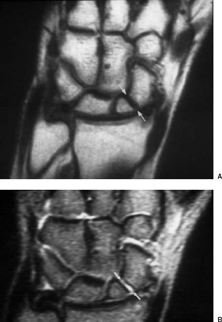
The incidence of fractures of carpal bones other than the scaphoid is much lower. The triquetrum is the second most commonly fractured carpal bone accounting for 14% of wrist injuries. The remaining carpal bones account for <5% of wrist injuries. The mechanism of injury is similar to scaphoid fractures and generally due to significant direct or indirect trauma. Triquetral fractures may result from a fall on the outstretched hand with extreme dorsiflexion or direct dorsal trauma. Lunate fractures may be related to direct trauma or chronic microtrauma and are classified based on the radiographic appearance. Stage I injuries present with normal radiographs. Stage II injuries demonstrate sclerosis of the lunate without collapse or fragmentation (see Fig. 13-35). Stage III injuries demonstrate collapse and fragmentation without (A) or with (B) fixed scapholunate dissociation. Stage IV lesions are similar to stage III, but with associated radiocarpal and midcarpal arthrosis.
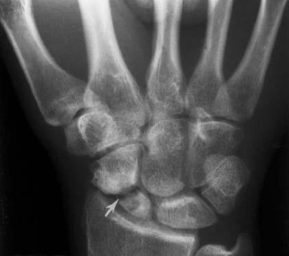
 Fig. 13-30 Scaphoid nonunion. Posteroanterior (PA) radiograph demonstrating an ununited (arrow) scaphoid waist fracture.
Related posts:
Stay updated, free articles. Join our Telegram channel

Full access? Get Clinical Tree


