Fig. 2
AER handshake protocol
Considering AER from a computer vision point of view, it can be understood as a progressive image transmission technique [24]. AER sends the most relevant information first. In usual computer vision systems it is necessary to wait until the whole image is received before starting to apply image processing algorithms. In some specific environments with a poor bandwidth and with fast response demanding this delay may be critic. This is the situation in automotive environments. In computer vision applications for automotive scenarios there are some important technical restrictions [8]: buses are very slow, there are strict technical prerequisites and priorities signals that cannot be interrupted. These hard conditions can be satisfied by AER. AER is a method that allows the events processing at the time they are received, avoiding the bus bandwidth saturation and its interference with other more important signals. This is one of the principal AER advantages.
There is many other application fields of the AER technology in the area of artificial vision and several works have been published, but all of them are laboratory applications not tested in real environments. In [2] it is presented a 2-D chip convolution totally based on pulses, without using the concept of frames. The information is represented by a continuous flow of self-timed asynchronous events. Such events can be processed on the fly by event-based convolution chips, providing at their output a continuous event flow representing the 2-D ( pixels) filtered version of the input flow.
pixels) filtered version of the input flow.In [9] it is presented an AER based layer to correct in real time the tilt of an AER vision sensor, using a high speed algorithmic mapping layer. It has been used a co-design platform (the AER-Robot platform), with a Xilinx Spartan 3 FPGA and an 8051 USB microcontroller.
Another application is explained in [7] which proposes cascade architecture for bio-inspired information processing. Using this architecture, a multiple object tracking algorithm is presented. This algorithm is described in VHDL and implemented in a Spartan II FPGA.
On the other hand in [12] it is shown a visual sensing experiment, processing and finally actuating on a robot. The AER output of a silicon retina is processed by an AER filter implemented in a FPGA to produce a mimicking behaviour in a humanoid robot. The visual filter has been implemented into a Spartan II FPGA.
Another example of visual-motor control is presented in [3], where a DVS is used to provide fast visual feedback for controlling an actuated table to balance an ordinary pencil on its tip. Two DVSs view the pencil from right angles. Movements of the pencil cause spike address-events (AEs) to be emitted from the DVSs. These AEs are processed by a 32-bit fixed-point ARM7 microcontroller (64 MHz, 200 mW) on the back side of each embedded DVS board (eDVS). Each eDVS updates its estimation of the pencil’s location and angle in a bi-dimensional space for each received spike (typically at a rate of 100 kHz). This task is done by applying a continuous tracking method based on spike driven fitting to a model of the vertical rod-like shape of the pencil. Every 2 ms, each eDVS sends the pencil’s tracked position to a third ARM7-based controller, which computes pencil location in the three-dimensional space and runs a linear PD-controller to adjust X-Y-position and velocity of the table to maintain the pencil balanced upright. The actuated table is built using ordinary high-speed hobby servos.
Additional AER-based image processing algorithms have been presented in different works like [5, 22, 23].
The work presented in this chapter is an application of AER technology designed for working in real world conditions in an automotive context, which takes a further step in bringing this technology to more complex environments.
If the analysis of the state of the art is done regarding classical computer vision techniques applied for driver monitoring, several works have been presented, like [4, 15]. Video systems usually produce a huge amount of data that likely saturate any computational unit responsible for data processing. Thus, real-time object tracking based on video data processing requires large computational effort and is consequently done on high-performance computer platforms. As a consequence, the design of video-tracking systems with embedded real-time applications, where the algorithms are implemented in Digital Signal Processor is a challenging task.
However, vision systems based on AER generate a lower volume of data, focusing only on those which are relevant in avoiding irrelevant data redundancy. This makes possible to design AER-tracking systems with embedded real-time applications, such as the one presented in this chapter, which indeed, it is a task much less expensive. Several examples are shown in [3, 7].
The chapter will be structured as follows. In Sect. 2, it is explained the DVS and the labelling events module. In Sect. 3, hands-tracking algorithm is described. The experimental results of the presented algorithm on real tests are shown in Sect. 4. Finally, in Sect. 5 conclusions are presented.
2 Hardware Components Description
The data acquisition is implemented by two devices: the sensor and the USBAERmini2 DVS, generating the information encoded in AER format.
The DVS sensor (silicon retina) contains an array of pixels individually autonomous with real-time response to relative changes in light intensity by placing address (event) in an arbitrary asynchronous bus. Pixels that are not stimulated by any change of lighting are not altered, thus scenes without motion do not generate any output.
The scene information is transmitted event to event through an asynchronous bus. The location of the pixel in the pixel array is encoded in the so-called address of events. This address, called AE (Address Event), contains the (x,y) coordinates of the pixel that generated the event. The DVS sensor used considers an array of  pixels, so 7 bits are needed to encode each dimension of the array of pixels. It also generates a polarity bit indicating the sign of contrast change, whether positive (light increment) or negative (light decrement) [11].
pixels, so 7 bits are needed to encode each dimension of the array of pixels. It also generates a polarity bit indicating the sign of contrast change, whether positive (light increment) or negative (light decrement) [11].As shown in (Fig. 3), the direction AE consists of 16 bits, 7 bits corresponding to the previously mentioned coordinates (x,y) , one bit of polarity and a bit NC.
The AE generated is transmitted to USBmini2 on a 16-bits parallel bus, implementing a simple handshake protocol. The device USBAERmini2 is used to label each event that is received from the DVS with a timestamp. This is relevant to maintain the time information in this asynchronous approach. The main elements of the USBAERmini2 device are FX2 and FPGA modules. The FX2’s 8051 microcontroller is the responsible of setting the “endpoints” of the USB port, in addition to receive and interpret commands from the PC (Fig. 4).
On the other hand the CPLD is responsible of “handshaking” with the AER devices, connected to the ports, and of reading and writing events in the FIFO’s FX2 module.
CPLD module has a counter that is used to generate the “timestamp” to label the events. Using only 16 bits is not enough, because only  timestamps could be generated, which is the same as 65 ms when using a tick of 1
  s. This is clearly not sufficient. But if more bits are considered, like 32 bit timestamps, it consumes too much bandwidth, as the higher 16 bits change only in rarely occasions. So as optimal solution, and to preserve this bandwidth, a 15 bit counter is used on the device side, and another 17 bits (so-called wrap-add throughout) are later added by the host software for monitoring events [1].
timestamps could be generated, which is the same as 65 ms when using a tick of 1 s. This is clearly not sufficient. But if more bits are considered, like 32 bit timestamps, it consumes too much bandwidth, as the higher 16 bits change only in rarely occasions. So as optimal solution, and to preserve this bandwidth, a 15 bit counter is used on the device side, and another 17 bits (so-called wrap-add throughout) are later added by the host software for monitoring events [1].Fig. 3
AE address structure
Fig. 4
System architecture
Both devices plus three infrared lights conform the system black box, which is shown in Fig. 5. The whole system has been conveniently package for easy installation of the system in different vehicles and in order to avoid bumps. Infrared illumination was used in order to avoid damaging the driver’s visibility and interfere in the driving task. Besides that, it makes the system much more independent of lighting conditions (day or night). A visible light filter was added to the DVS lens to allow only infrared information acquisition.
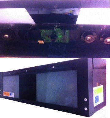
Fig. 5
Portable packaged system
3 Hands Tracking Algorithm
The developed algorithm is absolutely based in AER information, considering its intrinsic characteristics. The proposed algorithm performs a permanent clustering of events and tries to follow the trajectory of these clusters. The algorithm focuses on certain user-defined regions called regions of interest (ROI), which correspond to certain parts of the front compartment of a vehicle (wheel, gearshift, …). These different ROIs are customizable, allowing the user to define several shapes, sizes or number of regions. The events received are processed without data buffering, and can be assigned to a cluster or not, based on a distance criterion. If the event is assigned to a cluster, it will update the values of the cluster, such as position, distance, and number of events [14].
The algorithm can be described in detail as follows:
(a)
 e-Slide in the e-Laboratory of Cytology: Where are We?
 Heritage and 3D Models
 Sampling and Reconstruction for Sparse Magnetic Resonance Imaging
 of In-Plane and Off-Plane Surface Displacements with Grids Virtually Applied to Digital Images
 Image Processing
 Image Segmentation by Weighted Image Gradient Norm Terms Based on Local Histogram and Active Contours


Related posts:
Stay updated, free articles. Join our Telegram channel
Full access? Get Clinical Tree
