HEAD AND NECK IMAGE ACQUISITION AND DISPLAY: INTRODUCTION AND GENERAL PRINCIPLES
KEY POINTS
- Voxel concept
- Relative strengths and weaknesses of computed tomography, magnetic resonance imaging, and ultrasound
- Display of images
- Protocol planning–Problem-based imaging choices
- Workflow
IMAGING: WHERE TO START
At the time of medical decision making, there is often a triage decision required between the various available imaging tools. The tactical decision is essentially how a particular imaging tool might facilitate the medical decision-making process. The choice most often comes down to computed tomography (CT) or magnetic resonance imaging (MRI). Less often, ultrasound, radionuclide studies, or angiography will be an appropriate initial choice. This section considers the general relative roles and technical trade-offs between these powerful imaging tools. These applied fundamental technical considerations also form the basis for how protocols and workflow plans for head and neck imaging are best developed.
CT and MRI are powerful imaging tools when their technical parameters are optimized. Their inherent strengths and weaknesses frequently make them complementary for a specific clinical problem. Practically, one of the two normally needs to be chosen as the primary study in each patient who comes to such a triage point. Medicine is driven by high technology, cost containment, and increasingly sophisticated patients as well as a variety of treatment options for a given problem. The diagnostic radiologist (imager) should direct the diagnostic imaging choice and workflow. Factors affecting the choice of imaging studies are medically, socially, and economically driven.
The fundamental medical questions include the following: (a) Is an area normal or abnormal? (b) If it is abnormal, what is the nature and extent of disease? (c) How can all of the diagnostic information that is critical to medical decision-making/treatment planning be obtained with the least risk to the patient? The relative importance of socioeconomic considerations such as cost, reimbursement policies, available technology, throughput, and clinician acceptance, among other factors, varies greatly between countries, institutions, and imaging groups. These important issues will not be addressed specifically.
This text will always attempt to give a clear and balanced idea of which major tool should be used first or, if possible, exclusively in a given clinical situation. This choice is driven by appropriate clinical triage and managed optimally with properly focused imaging protocols. The need or preference for imaging studies other than CT and MRI is always emphasized when appropriate. In best practices, the safest and most efficacious imaging study is done first with the greatest possible attention to detail. A follow-up, adjunctive study should be more focused if such a study is critical to clinical decision making. In certain instances, a study may be chosen that might not make the most appealing image. For instance, ultrasound may be chosen in a pediatric neck mass since it can be done without sedation or ionizing radiation, but it might not prove to be definitive. Assuming the first study is chosen wisely, studies beyond the initial one should provide answers to specific questions left unanswered by the first. The primary responsibility of the diagnostic radiologist is to produce a safe, high-quality imaging evaluation that correctly answers all critical clinical management questions. The study quality is always highly dependent on operator selection of specific technical parameters. This basic image quality sets the baseline for image interpretation.
Chapters 1 through 5 focus on the general principles of major imaging techniques that allow these tools to be manipulated to produce the most clinically relevant data. These chapters provide general guidelines for an adequate study based on currently available technology. The physical principles are then applied to general protocol building and workflow guidelines for each modality. This section (Chapters 1–5), essentially on applied physics, is mainly a reflection of the many important underlying physical principles of CT, MRI, ultrasound, and radionuclide studies. A more in-depth discussion of the physical principles of these modalities is available in many other excellent resources.
SPATIAL RESOLUTION: VOXEL SIGNAL-TO-NOISE RATIO AS A FUNDAMENTAL CONCEPT IN COMPUTED TOMOGRAPHY AND MAGNETIC RESONANCE IMAGING
The volume element (voxel) is the basic unit of image reconstruction. As such, it is a core concept for imaging systems that reconstruct images in a planar or volumetric manner. Two “in-plane” dimensions of the voxel are defined as the x and y measurements of the picture element (pixel). The pixel is the basic unit of image display in the plane of reconstruction. The slice thickness (z axis) defines the voxel’s third dimension (Fig. 1.1). These dimensions are always under direct operator control and are the prime determinants of spatial resolution. The voxels are always anisotropic due to z-axis (slice thickness) issues. Some manufacturers like to represent that that CT voxels can be made isotropic. Simple arithmetic shows this not to be true, even theoretically or virtually, in head and neck work. The 512 × 512 matrix divided by the typical field-of-view (FOV) range of CT reconstructions of 9 to 16 cm gives a range of about 0.18 to 0.30 mm for the x and y dimensions of the pixel. The nominal 0.500- to 0.625-mm segmentation of current CT detectors obviously exceeds those dimensions. Sections can be reconstructed at half the detector segmentation distance, but that still exceeds the usual pixel dimension with a 16-cm FOV, which is about the largest used in high-quality head and neck imaging outside of the 20-cm FOV typically used to study the brain. The fact is that data from volume acquisition can approach the isotropic goal but is it does not meet such a specification. MR voxels can never really approach isotropy even with thin-slab three-dimensional Fourier transform (3DFT) acquisitions.
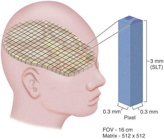
FIGURE 1.1. Schematic diagram showing the concept of the voxel. Manipulation of voxel size is an extremely important concept in developing proper computed tomography and magnetic resonance protocols, as discussed in detail in this chapter and in Chapters 2 and 3.
The signals utilized to reconstruct CT and magnetic resonance (MR) images arise from different subatomic components of the tissues being imaged. In CT, the signals sampled, known as projections, refer to the differential attenuation (i.e., the interaction of photons with electrons within each voxel) of an x-ray beam by the various tissues being imaged. Thus, in CT, the electron density per voxel determines the signal per voxel. In MRI, the signal results from the differential response of the tissue protons immersed in a strong magnetic field and the surrounding local magnetic fields that continually change due to the presence of gradient and radiofrequency pulses. Thus, the signal not only depends on the proton density per voxel but also on the particular response of the various tissues to the changing magnetic fields. This response is characterized by two tissue-characteristic parameters, known as the longitudinal (T1) and the transverse (T2) tissue relaxation times.
Image quality is completely described by four attributes: image contrast, spatial resolution, signal-to-noise ratio (SNR), and artifacts. The concept of these four indicators is complex, mainly because of the interrelationships among them. Thus, in a clinical study, the clinical interest determines which of the four indicators has priority over the others. A simplified working knowledge of these complex relations is essential for the radiologist who is asked to plan and design protocols and diagnostic studies and give advice on major equipment purchases.
To illustrate this issue, let us first consider the interdependence between image contrast and spatial resolution. In order for two objects to be seen as separate entities in a digital image, they must be contained in adjacent voxels with different signal intensity as observed by the detection system and eventually by the reconstruction algorithm. This different signal is the most basic definition of image contrast. No matter how small the voxel (i.e., increased spatial resolution), if there is no contrast (i.e., no signal difference) between two adjacent voxels, it is impossible to tell them apart. Second, to illustrate the dependence between SNR and contrast, consider scanning air, which contains very few electrons or protons. Careful inspection of the displayed pixels will show slight variations in signal distributed randomly across the “image”; however, there is no defined structure to the image. The variation seen is statistical in nature, mainly due to the quantum nature of photons, electrons, and protons but also due to background noise that is mainly related to system electronics. If two voxels are to be reliably resolved, the difference in their signal (contrast) must be greater than the background statistical variations caused by quantum and system noise. Thus, the concept of the signal above the statistical variations introduces a second fundamental concept in this and other imaging systems—the SNR. Recall that the first fundamental concept was the definition of a voxel. Since noise varies statistically over the entire image, one may consider signal per voxel the basic building block of a CT, MR, or any other digital image.
If two objects in an image differ enough in contrast (signal per voxel) to be seen as separate, then the spatial resolution of the system may be defined as the shortest distance at which they can be actually perceived as separate from one another. The image contrast for those two objects can be thought of as a parameter setting the threshold for spatial resolution. Both contrast and spatial resolution are affected by altering voxel size or, more fundamentally, by altering the number of protons per voxel with MRI or number of electrons per voxel with CT. This is discussed in detail later. The two concepts are interrelated in a complex manner that has led to the development of a useful concept called relative resolving power (T).1 In the following discussions, image contrast and spatial resolution are treated separately to emphasize the operator-dependent variables used to improve the overall resolving power of the CT or MRI unit. This fundamental concept together with clinical demands then drives the setting of image acquisition parameters for various imaging protocols.
Catheter angiography is a digital technique used in almost all practices. Its inherent resolution is essentially related to the image acquisition chain and will not be discussed to any greater degree.
In ultrasound imaging, axial resolution is primarily determined by the transducer frequency, although lateral resolution is related to pixel size. The frequency of the transducer used must be matched to the required depth of tissue penetration to examine the area of interest. Fortunately, for head and neck imaging, high-frequency, so-called “small parts” transducers (10 to 15 MHz) capable of the greatest spatial resolution can be used in most patients and especially in the pediatric age group.
In radionuclide techniques, spatial resolution is a fundamental limitation influenced by primary gathering of physiologic information. It is highly dependent upon the particular tracer being used and the camera configuration used for the acquisition as well as the lesion-to-background ratio. Further discussion of this is beyond the scope of this text.
COMPARATIVE STRENGTHS AND LIMITATIONS OF COMPUTED TOMOGRAPHY AND MAGNETIC RESONANCE IMAGING
This text deals very specifically with the relative usefulness of CT and MRI in lesions of the head and neck in appropriate anatomic and disease entities. At this point, the strengths and limitations are considered more generally. This discussion does not consider MRI field strength specifically since adjustments can be made to level some of the potential limitations of lower field strength units. It is presumed that most head and neck imaging is done optimally at 1.0 to 1.5 Tesla (T). The 3.0-T units do not add a measurable increment of diagnostically important information over 1.5-T units for the applications under discussion in this text. The 3-T unit is more useful in functional MRI; diffusion-weighted imaging, including advanced diffusion tensor imaging and quantitative analysis; spectroscopy; and improved quality of magnetic resonance angiography (MRA). It is simply inappropriate to do studies that require high detail at lower field strengths than 1 T except under extenuating circumstances.
Contraindications and Relative Failure Rates
MRI examinations are contraindicated in patients for a variety of well-known reasons. All MRI facilities have strict intake interviews to avoid potentially lethal situations (e.g., cerebral aneurysm clips subject to torque). Cochlear implants and stapes prostheses may be found with more frequency in a practice that includes a large number of referrals from otolaryngologists; modern stapes prostheses rarely present a problem.2 Cochlear implant patients can be safely studied at lower field strengths with proper precautions. A small number of patients will be too claustrophobic to study. This rate can be improved in more open designs but cannot be eliminated.
Critically ill patients can be studied with MRI. The logistics of patient monitoring and maintenance of vital functions are difficult in MRI units and at times impossible in very unstable patients. Critically ill patients are routinely and relatively easily studied with CT. Optimal design of MRI suites to accommodate specialized monitoring, and anesthesia equipment and/or installation of higher-field open architecture systems, can help improve limitations of MR in this regard.
Suboptimal to marginally diagnostic MRI studies due to excessive motion artifact are common. In the pediatric age group, moderate conscious sedation is reasonably effective at relieving this problem. Deeper sedation is >95% effective but poses increased risk, requiring more intensive supervision of sedation. In adults, sedation often does not help except in the mildly claustrophobic group. Faster pulse sequences and parallel acquisition techniques can reduce the poor study quality rate in patients who are unable to fully cooperate. Overall, CT retains a clear advantage over MRI in the rate of suboptimal or failed studies due to all of the circumstances outlined above. This represents a distinct advantage of CT over MR, especially in a primarily hospital-based practice.
Examination Time
An average CT study of the head and neck region on a multislice scanner takes about ≤10 minutes of table time and much less for data acquisition time. An average MRI examination (on a 1.0- to 1.5-T unit) requires at least ≥30 minutes on the table for an examination with similar goals. This is mainly related to the complexity of data acquisition MRI protocols. Simple MRI studies, such as routine evaluation for a cerebellopontine angle mass/eighth nerve lesion, can be completed in 20 to 30 minutes. The time advantage is important economically as well as for patient care. Some patients will become fatigued or “fidgety” after five or six major data acquisitions or about 30 to 45 minutes, and the rate of failed or suboptimal acquisitions rises as the time of examination lengthens. The time factor becomes even more important on low and midfield MR units that require more signal averaging to produce images of acceptable quality.
The potential complexity of MRI examination, which requires T1- and T2-weighted images, multiplanar options, images with and without paramagnetic contrast, and/or fat suppression, results in many of its advantages actually impeding throughput in a survey situation. For instance, the entire upper aerodigestive tract and neck can be studied in a maximum table time of 10 minutes on CT in a patient with a neck node from an occult primary tumor. Such an “unfocused” MRI study might take at least two to three times longer to produce the same information. In general, MRI is in its best and most efficient mode when its considerable advantages in tissue contrast are focused on a confined region of anatomic interest. There are exceptions to this, and the relative advantages of CT and MRI with respect to efficiency of examination must be decided on a case-by-case basis since there are so many competing factors.
Artifacts
All imaging systems generate artifacts, but those found in MRI are more numerous and possibly more likely to be interpreted as pathologic change by inexperienced observers. Gross motion artifacts were discussed previously and pose a far more significant problem for MRI when compared with CT. Gross motion is mainly a problem outside of the brain and below the hard palate. Eye movements degrade orbital and eye images. Jaw motion may obscure important detail in the oropharynx and oral cavity. Swallowing and labored breathing routinely degrade laryngeal and hypopharyngeal studies, and this may be compounded in patients with cancers in the region that aggravate airway problems due to partial obstruction and swallowing and coughing because of increased secretions or chronic inflammation. The rate of technically inadequate MRI studies is about 10% in patients with oropharyngeal, laryngeal, and hypopharyngeal cancer because of these factors. Marginally diagnostic studies occur in at least another 10% to 20%. The rate of marginally diagnostic or failed CT studies is near zero. As a contrast, in the nasopharynx and parapharyngeal space, motion is normally not a problem and MRI is the preferred primary examination because of its superior contrast resolution and depiction of major vessels and nerves.
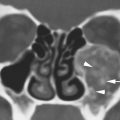
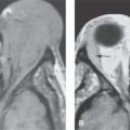
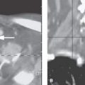
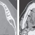
Flow-related MRI artifacts from both blood and cerebrospinal fluid might degrade images, hide pathology, and lead to misinterpretation (Fig. 1.2). Dealing with flow-related artifacts often increases the complexity of performing and interpreting MRI studies. This is often a disadvantage, especially around the posterior skull base and jugular fossa. These same flow-related “artifacts,” or lack thereof, may be the source of important and unique diagnostic information. The diagnostic utility of flow phenomena and MRA are discussed in detail as appropriate in specific regions of anatomic and pathologic interest. Some examples are seen in Figures 15.8, 15.13, and 33.4. One must be totally familiar with these phenomena so as not to make critical errors in reading MRI studies of the head and neck and other regions.
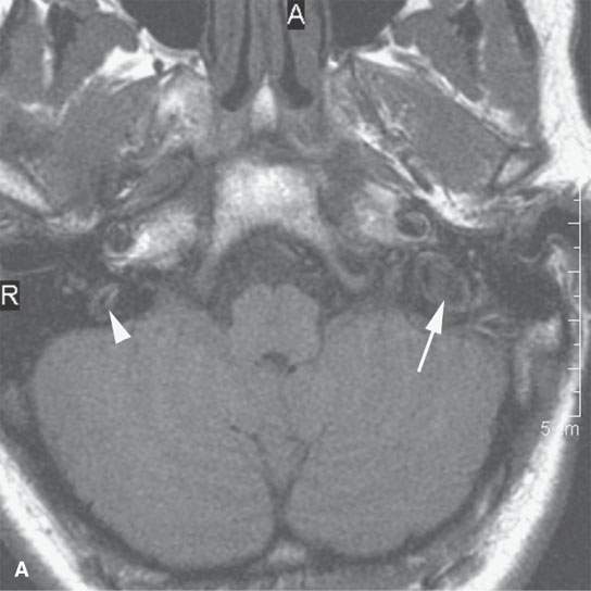
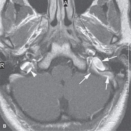
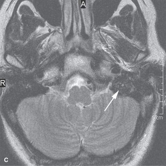
FIGURE 1.2. Flow-related artifacts as seen on magnetic resonance imaging (MRI). A: T1-weighted non–contrast-enhanced image shows variable signal intensity in the vicinity of the jugular fossa on the left (arrow) and to a lesser extent on the right. B: Contrast-enhanced T1-weighted images show enhancement in these same areas. The complexity of the flow dynamics on the left in the vicinity of the jugular bulb and sigmoid sinus (arrows) is manifest as the variable signal intensity. Also note that the flow-related artifacts are enhanced and appear more complex on the right as well (arrowhead). C: T2-weighted image showing dephasing of the blood in these areas of turbulent flow so that only a somewhat speckled area of increased signal intensity is present on the left side. (NOTE: Flow-related artifacts can be useful in diagnosis. They can also lead to serious misinterpretation sometimes being represented as pathology. These artifacts make MRI not definitive for excluding jugular fossa region pathology unless the normal vascularity is definitively established.)
Related posts:
 Fibrous Dysplasia and other Fibro-osseous Lesions of the Craniofacial Skeleton
 Intraconal Orbit: Tumors
 Hypopharynx: Developmental Abnormalities
 Tumors of the Submandibular Gland and Space and Tumorlike Conditions
 Oral Cavity and Floor of the Mouth: Malignant Tumors
 Benign and Malignant Epithelial Tumors: Lesions of Cutaneous (Skin) Origin
Stay updated, free articles. Join our Telegram channel

Full access? Get Clinical Tree


