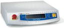
3.2.1.2 Control Console
The XRS is powered by this component. The control console receives instructions from the user terminal to perform QC and treatment tasks. It executes them, monitors them and displays current data during the process. The XRS provides the control console with feedback signals regarding the operational status of the variables relating to X-ray production, interlock status, etc. It sends raw data back to the user terminal, which are then transformed into QC and treatment records. The XRS is connected to the control console via a low-voltage (12-V) cable. An air pressure sensor located within the control console is used to correct output measurements.
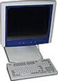
3.2.1.3 User Terminal and INTRABEAM Software
This is the primary interface between the user and the INTRABEAM system. The user is able to set up the control console to perform the main functions of the system: pre-treatment verification, treatment planning, logging of all procedure variables and events, and saving and printing of treatment and performance data. The integrated user terminal has been designed for easy transport and safe use in theatres.
3.2.2 Verification Components
The INTRABEAM is supplied with a range of shielded accessories used during the pre-treatment procedure.
3.2.2.1 Photodiode Array (PDA)
This is used to determine the optimum voltage from the deflection coils in the X and Y directions and isotropy settings of the XRS prior to treatment. It contains five diodes placed on the four side faces and the top face of a cube, such that all are equidistant from the centre of radiation of the XRS probe. When the probe is inserted into the PDA, the axis markings on the side of the PDA housing must be aligned with the matching axis marking on the XRS housing. Signals from the PDA will be displayed on the user terminal measuring the distribution (isotropy) of X-rays emitted from the tip of the probe.
3.2.2.2 Probe Adjuster/Ion Chamber Holder (PAICH)
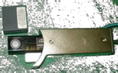
The PAICH (Fig. 3.1) has two primary functions: (1) to maintain straightness of the XRS probe and (2) to provide a means of accurate positioning of an ionisation chamber in relation to the probe tip. It is essential for the XRS probe to be straight in order to maintain an isotropic radiation output. The “runout” (deviation from perpendicular) of the probe is determined using the probe adjuster. Probe straightness is measured optically to 0.1 mm by a method in which the probe intercepts a portion of a light beam from an LED across one edge of the tip of the tube. The light beam is detected as it strikes an opposing photodiode. As the PAICH is rotated around the probe, any mechanical deviation of the tube from the axis of rotation will be represented by a change in the light detected.
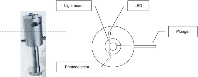
Fig. 3.1
Top view diagram of PAICH cross-section
3.2.2.3 Electrometer and Ion Chamber (IC)
A shielded IC (type PTW 23342 for very low radiation therapy energies) parallel plane chamber is used to verify the output of the XRS and to calibrate the IRM readings. The electrometer (PTW Unidos E) measures and displays the current generated by the IC. The customised shield serves not only to provide radiation safety but also to reproducibly position the chamber inside the PAICH with respect to the tip of the probe whenever taking output measurements.
3.2.2.4 External Radiation Monitor (ERM)
Older INTRABEAM systems (i.e. PRS 400) utilised a radiation detector external to the XRS, measuring the radiation exiting the patient. The ERM used detectors with the purpose of independently monitoring the constancy of the radiation emitted by the XRS and during the course of treatment, thus providing a further backup to the timer for controlling dose delivery and end of treatment. New systems do not include this external monitor.
3.2.3 Other Components
3.2.3.1 Applicators
Spherical applicators, ranging from 1.5 to 5 cm in 0.5-cm increments, fill the entire cavity left after tumour excision. The XRS probe is located in the centre of the applicator, and thus the tumour bed. The material of the applicator is medical-grade acrylic and it can be steam sterilised up to 100 times. For smaller applicators, aluminium is inserted around the cavity where the tip of the probe will be present (Fig. 3.2). This is to remove lower energy characteristic line from the radiation spectrum due to the presence of components at the probe tip other than the gold target material. For larger applicators, the thickness of the material will be sufficient to harden the beam. The aluminium will also reduce the higher signal that would otherwise be obtained from radiation passing back through the probe as these photons go through less material with decreasing applicator diameter.
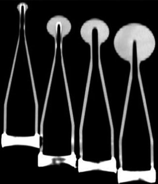

Fig. 3.2
CT image showing cross-sections of 1.5, 3.0, 3.5 and 5.0 cm diameter applicators, illustrating the aluminium inserted in the two smallest applicators
The treatment time for each applicator is worked out using the “transfer function” for the relevant applicator and PDD data of the bare probe as given in the calibration files.
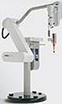
3.2.3.2 Stand
The stand allows positioning of the XRS with 6 degrees of freedom. Electromagnetic clutches lock the radiation source in the treatment position. The stand requires careful balance setup for weight compensation.
3.2.3.3 Interlock System and Safety Features
The whole system features various interlock mechanisms to avoid unintended radiation emission and loss or incorrect data transmission. Radiation emission is audio and visually indicated on the X-ray source and user interface. Further safety systems such as a theatre door switch can be added to an external interlock switch on the INTRABEAM control console. The count rate is constantly monitored by the IRM and its ratio with the planned treatment time is checked via the control console. Any deviation from tolerance will stop any emission of radiation. The system also features an optical interlock able to detect whether the appropriate verification device has been correctly attached to the X-ray source, whether the source has been mounted correctly onto the floor stand and whether an applicator has been correctly attached to the floor stand. The INTRABEAM PRS500, and older versions, is not capable of detecting the applicator size. For this reason, it is recommendable to independently verify such parameters once the surgeon has attached it to the stand. Finally, the software follows a series of verification steps such that only when they have been correctly completed by trained and authorised staff will emission of radiation be allowed.
3.2.3.4 Ancillary Components
Ancillary components include connectors that will provide signal feedback and low-voltage power between different components; V&X block guides for the safety coupling between the XRS and pre-treatment components; and a protector sheath to cover the XRS probe while not in use or out of its carrying tray.
3.3 Calibration of the System
The dosimetry check of the INTRABEAM is predefined by the manufacturer, Zeiss, with calibration files linked to the XRS serial number provided on a CD to be loaded onto the user interface. Calibration of the XRS to quantify the depth dose rate characteristics (PDDs) of its X-ray emission must be performed annually. These PDDs and other checks such as output measurements are carried out at the Carl Zeiss manufacturing plant using their own water phantom (simliar to the commercially available model shown in Fig. 3.3).
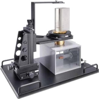
Fig. 3.3
Zeiss water phantom
The purpose of any commissioning study by the hospital’s radiotherapy department will be to develop and implement a method to independently verify the internal dosimetry of the system vs. quoted data: dosimetric determination of the PDDs (with bare probe and with applicators), absolute dose, isotropy and long-term stability of the XRS. These independent verification tests will be explained in the chapter “Quality Assurance and Commissioning”. Here, we will only cover the sequential procedures designed to verify the correct operation of the INTRABEAM system prior to patient treatment.
These checks, specifically dose calibration and probe straightness, are vital to ensure accuracy of dose delivery. This is because, since the electrons are made to drift along a thin tube of 3 mm outside diameter and 2 mm inside diameter, any bending of more than 0.1 mm in the tube will reflect the electrons back and will reduce the output dose rate per minute.
3.3.1 Treatment Verification Tests
When logging in the user terminal, the software will display the “System Quality Assurance” tab by default. Once the XRS in use has been selected, the following optional and mandatory tests are performed prior to treatment:
3.3.1.1 Probe Adjuster (Optional Test, PAICH Tool)
The probe adjuster is used to verify and, if necessary, adjust the straightness of the XRS probe to ensure proper alignment of the electron beam with the mechanical centre of the probe (Fig. 3.4). This test will be performed if the isotropy verification test has been unsuccessful and/or the XRS probe is suspected to be bent. Insert the XRS into the PAICH and connect both to the control console. The two bar graphs on the right side of the window display the current deviation of the XRS probe as the PAICH is rotated 360°, with the second graph indicating the same deviation at a different sensitivity setting. As the PAICH is rotated, the deviation bar moves. The runout must not exceed the specified tolerance (0.10 mm). This is calculated according to the formula below, where the maximum and minimum deviations are the values of the high and the low cursor associated with each bar.
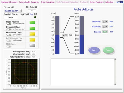
Fig. 3.4
Probe adjuster window
If the probe needs adjusting, press “Zero” before rotating the PAICH around the probe to where the deviation bar is at its maximum. At this point, depress the plunger and then release it. After releasing the plunger, the bars should be closer to the centre of the graph.
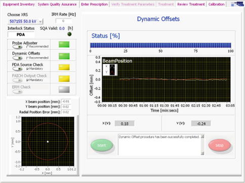
3.3.1.2 Dynamic Offsets (Optional Test, PDA Tool)
This test must be run after centring the XRS probe. It verifies the stability as well as the beam position over a period of time at the deflector coil voltages set for optimum output (electron beam centred on the target). With the XRS probe inserted into the PDA, align the +X and +Y markings on both the XRS and the PDA. Both the XRS and the PDA must be connected to the control console. Once the process has been started, it will run automatically and last a few minutes. During this time, the main beam position graph should show both coordinate signals (X and Y) to be approximately flat with no fluctuation greater than ±0.1 mm around 0 (beam centre) (Fig. 3.5). The graph at the bottom left corner will provide the same information radially.
 Targeted Intraoperative Radiotherapy: Concept and Review of Evidence in Breast Cancer
 Follow-Up Findings in the Tumour Bed After IORT – What the Radiologist Needs to Know
 Quality Assurance and Training of Targeted Intraoperative Radiotherapy: Establishment of the TARGIT Academy
 Treating Patients with TARGIT
 Radiation Protection
 Intraoperative Photon Radiosurgery in Patients with Malignant Brain Tumours


Related posts:
Targeted Intraoperative Radiotherapy: Concept and Review of Evidence in Breast Cancer
Follow-Up Findings in the Tumour Bed After IORT – What the Radiologist Needs to Know
Quality Assurance and Training of Targeted Intraoperative Radiotherapy: Establishment of the TARGIT Academy
Treating Patients with TARGIT
Radiation Protection
Intraoperative Photon Radiosurgery in Patients with Malignant Brain Tumours
Stay updated, free articles. Join our Telegram channel
Full access? Get Clinical Tree
