Fig. 28.1
Information content from two imaging modalities typically overlaps in certain aspects. Image fusion can merge complementary information from two or multiple imaging modalities
We will first consider briefly advantages and limitations of common medical imaging technologies. Since the 1970s, CT usage has increased rapidly, and it is estimated that today more than 72 million scans are performed annually in the USA alone [1]. Although CT imaging is user-friendly and allows rapid image acquisition, concerns have been voiced recently regarding repetitive usage and radiation exposure resulting in a possible increase of life-time cancer risk [2]. Additionally, contrast agents that are required for some studies can lead to renal impairment and hence renal function should always be considered in image modality selection.
MR imaging provides excellent soft-tissue contrast and is free of ionizing radiation. MRI utilization is rapidly growing and today approximately 30 million annual scans are performed in the USA [3]. However, availability of MRI systems is limited and imaging costs are high compared to those of CT. The major contraindications to MRI are metallic implants in the body such as aneurysm clips, cochlear devices, spinal nerve stimulators, pacemaker, implantable cardioverter-defibrillator (ICD), and deep brain stimulators. Patients are frequently imaged using Gadolinium-based contrast agents. Gadolinium chelates are extravascular MRI contrast agents that are cleared by the renal system. Individuals with severe renal impairment may therefore experience adverse effects with the use of these contrast agents, and hence clinically, patients are screened for their kidney function by estimating the glomerular filtration rate (GFR).
PET is a functional imaging modality involving a radionuclide such as fluorodeoxyglucose (18F-FDG) which is intravenously injected after which the location of the tracer throughout the body can be determined for diagnostic purposes [4]. PET imaging has been very successful, especially in oncology [5]. One of the concerns regarding PET/CT imaging studies is the level of radiation exposure that can be in the order of ten to above 30 mSv per scan, depending on imaging protocols [6]. Moreover, at present the availability of PET imaging is limited and scanning costs are high. One of the major technical limitations of PET imaging is poor resolution when compared with other imaging modalities. The fusion of PET/CT systems alleviated the limitation of image resolution in part and also increased availability to approximately 2,000 installed systems in 2010 [7].
Ultrasound imaging is among the safest of imaging modalities with several advantages including portability and excellent temporal resolution. Moreover, US is a widely available versatile medical imaging technology. US has no known long-term side effects, and the modality can be used to image soft tissue, vasculature, blood flow, muscle, and bone surfaces (Fig. 28.2). US technology is based on sound waves that are generated and detected by piezoelectric elements inside the US transducer. Sound waves travel in a beam originating from the transducer that also acts as receiver for the reflected and scattered echo signals that are subsequently converted into an image. Clinical US imaging systems utilize acoustic waves in the low MHz range resulting in limited tissue penetration depth and inability to penetrate bone. US imaging is, however, more operator dependent than CT or MR imaging and hence the sonographer training and experience are important factors of image quality. Another limitation of ultrasound imaging is its “lateral drop out” or loss of detail in the lateral segments of the image, i.e., the segments away from the ultrasound beam—which is a consideration in assessing atherosclerosis [8].
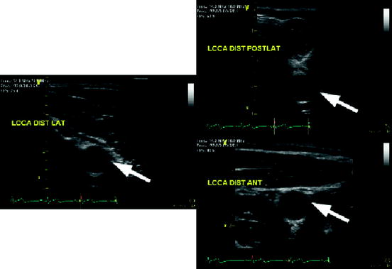
Fig. 28.2
US images of the left common carotid artery (LCCA) of one subject from different angles (views points). The white arrows indicate the same location in the LCCA illustrating changes in speckle patterns
2 Image Fusion
Image fusion presents the clinician and researcher with the opportunity to merge content from multiple imaging modalities, thereby possibly alleviating limitations of individual scanning technologies (Fig. 28.3). Image fusion can be implemented at the hardware or the software level. Table 28.1 lists clinically available image fusion systems such as, for example, PET/CT [4, 9] and recently available PET/MRI systems [10, 11]. Although image fusion is commonly understood as an inter-imaging modality technology, it can also be applied to intra-modality fusion; for instance to analyzing pre- and postoperative imaging data.
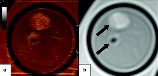
Fig. 28.3
Axial images of a carotid endarterectomy (CEA) sample. Panel (b) shows a proton density weighted MRI slice of the internal and external carotid artery (arrows). Note the hypointense region in the external carotid artery indicating the absence of plaque. Panel (a) depicts a fused image composed of the MRI slice and the corresponding ultrasound image
Table 28.1
Image fusion systems
Imaging modalities | MRI | US | CT | PET |
|---|---|---|---|---|
MRI | X | X | X | X |
US | X | X | X | |
CT | X | X |
Table 28.2 shows a summary of important characteristics of major imaging technologies. Broadly speaking, image fusion between one or more imaging modalities can be accomplished by hardware or software fusion.
Table 28.2
Summary of important parameters for the most commonly used clinical imaging modalities
Properties/imaging modality | MDCT/DS-MDCT | MRI | US | PET |
|---|---|---|---|---|
Ionizing radiation | Yes | No | No | Yes |
Temporal resolution | 165 ms/83 ms [12] | 12 ms [17] | 1 breathing cycle | |
Spatial resolution | 0.1–0.3 mm [23] | 5–8 mm [4] | ||
Reproducibility | Excellent | Excellent | Good but operator dependent | High |
Acquisition time | Excellent | Moderate | Excellent | Moderate |
Tissue contrast | Limited | Excellent | Limited | – |
Function | Yes | Yes | Yes | Yes |
Image fusion can be broadly classified into two categories, namely hardware fusion and software fusion.
2.1 Hardware Image Fusion
In the hardware-based approach to image fusion, data are acquired simultaneously by different imaging modalities. The advantage of these systems is that the resulting imaging data are co-registered, and data fusion is performed in real time. The disadvantages include the possible requirement of larger equipment.
2.1.1 Ultrasonography
Compound imaging or the fusion of information obtained through multiple scans of the same anatomy or region of interest has been one of the main approaches toward improving information obtained through ultrasound-based imaging. Compound imaging systems fuse images from separate sequential scans of the area of interest [24–28]. Jeong and Kwon [29] obtained US scans of human breast tissue using two opposing array transducers. Although these efforts improved the image quality and resolution, imaging was done sequentially and hence resulted in long scan times or suboptimal co-registration, i.e., the ability to obtain information in the same plane. The simultaneous usage of multiple transducers might exacerbate the known US limitation of lateral dropout leading to potential loss of information.
The issue of lateral dropout in US imaging has been addressed by fusing images obtained from different angles using a technique known as spatial compounding which has been an active field of ultrasound research aimed at reducing intensity variations due to interference patterns from tissue echoes known as speckles [28]. Jespersen et al. [27] developed a scanning method known as multi-angle compound imaging (MACI) that uses a linear phased array to create iteratively a beam at one of n-angles at a time producing a set of acquisitions from different angles. MACI averages all n-images resulting in better tissue contrast and reduced speckle noise. The basic concept of MACI was extended by Behar et al. [28] to improve lateral resolution and speckle contrast by simultaneous image acquisition using three laterally separated transducers with only one acting as transmitter resulting in a compound image. Spatial compounding and MACI reduce speckle and improve tissue contrast at the cost of a reduced image frame rate.
2.1.2 PET/CT/MRI
PET/CT is a very successful imaging technology that combines functional imaging with anatomical imaging [9]. Although technical designs and specifications differ among vendors, the PET detectors and CT components are mounted typically inside a single gantry resulting in a co-registered data acquisition of both modalities [30, 31]. The major CT components such as detectors, readout electronics, and the X-ray tube are mounted on a rotating ring. The PET detectors and electronics are mounted on a separate ring, partial ring, or are integrated in a stationary setup, depending on vendor specifications. Technical details on PET/CT scanner instrumentation can be found in an article by Alessio et al. [32].
In 2011 the US Food and Drug Administration approved the first commercial PET/MRI system for US market. PET/MRI is a promising technology, given its capability to simultaneously image function with increased soft tissue contrast at a significantly lower radiation burden [33, 34]. PET/MRI can reduce ionizing radiation by approximately 70 % when compared to state of the art PET/CT systems. Hence, this new technology might be especially of interest to vulnerable populations such as individuals receiving multiple scans and children.
2.2 Software Image Fusion
The software-based approach to image fusion is routinely used for the co-registration of images obtained with two or more modalities (Fig. 28.4). The process of image fusion involves several algorithmic steps that can vary substantially in number depending on the application at hand. Image fusion techniques integrate algorithms from the broad areas of computer vision and object recognition [35, 36]. Common problems that arise in image fusion are due to inherent differences in the underlying imaging technologies. For instance, in-plane resolution is quite different between US and MRI images. The image fusion algorithms need to be able to tackle these differences in a robust fashion. Figure 28.5 shows the typical steps used in software-based image fusion techniques.
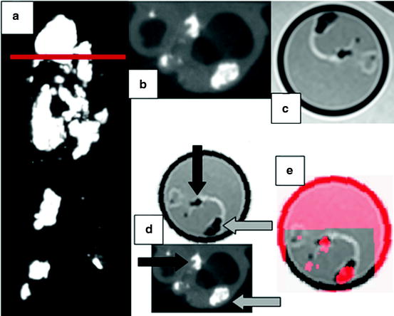
Fig. 28.4
Carotid endarterectomy (CEA) sample imaged with μCT and MRI. (a) Coronal view obtained with μCT for the CEA sample. Note the heavily calcified regions (bright areas). The horizontal red line indicates the location of the axial images in panels (b)–(e). (b) Axial slice at bifurcation of the μCT scan showing the internal and external carotid arteries with calcified nodules and increased wall thickness. (c) Co-registered MRI image acquired with a proton-density weighted turbo spin echo sequence on 3.T Siemens Verio system. (d) Euclidean transformed MRI slice in order to align with the μCT image. The black and gray arrows indicate calcified areas (hyperintense) serving as fiducial markers for image fusion. Note that calcified regions appear hypointense in MRI. (e) Representation of the fused μCT-MRI slices using transparency (best viewed in color) (Color figure online)
Fig. 28.5
Multi-modality image fusion workflow
One of the most important steps in the image fusion workflow is the co-registration of the multi-modality imaging data. This aspect requires the identification of anatomical landmarks that are present in all of the source images. Depending on the approach, these landmarks, which are commonly referred to as fiducial markers, need to be extracted automatically or manually. Clinically, semiautomatic approaches have proven superior since automatic algorithms may perform poorly in the presence of imaging artifacts. Subsequently, these fiducial markers are used to extract features which in turn play a vital role in the quality of the final image fusion output.
Features are a compact representation of an image’s content and of central importance in software-based image fusion systems. In the case of image fusion, the complexity of features can extend from simple coordinates of a set of fiducial markers to wavelet descriptors of selected regions of interest or include a set of features combining texture, structure, shape, motion, or entropy information[37–43]. The construction of features is of central importance in image analysis and image registration algorithms. It is beyond the scope of this chapter to discuss feature extraction in detail. Therefore, we will focus on the conceptual aspects, and the interested reader is referred to specialized literature on feature computation [35, 41, 44–52]. An important property of features for image fusion applications is invariance. Invariant features remain unchanged in case the image content is transformed according to a group action, i.e., the features obtained for an unaltered or a transformed image are mapped to the same point in feature space. A simple example is the color histogram of an image that remains identical under any permutation of the image pixels. However, a slight change in illumination, i.e., changing the actual values of pixels, may significantly change a simple color histogram. The concept of invariance considerably simplifies semi-automatic or fully automatic image co-registration. Instead of comparing images in all transformed instances, only one comparison has to be performed.
The next step in the workflow outlined in Fig. 28.5 is the actual registration algorithm that uses the features extracted from both modalities to establish correspondence between the imaging data sets. The most commonly used registration approach assumes a rigid scenario meaning that a set of rotations, translations, and perhaps a uniform scaling operation results in a correspondence between the imaging data. These operations are also known as a similarity transformation that consists of 4 degrees of freedom (DoF) in the case of a two-dimensional image, i.e., translation in x and y direction (2 DoF), in plane rotation (1 DoF), and uniform scaling (1 DoF). In order to solve the similarity transformation, a total of 2 points is sufficient. In the general 3D case such as a volumetric US or MRI study, the similarity transformation has a total of 7 DoF (3 translation, 3 rotation, 1 scaling) and requires at least 3 fiducial markers to obtain a co-registration between the data sets. The rigid registration approach works favorably for many applications. However, in cases where a patient’s anatomy changes such as, for example, when scans were taken pre and post a surgical or endovascular intervention, the rigid registration approach delivers suboptimal results. In these cases image fusion can be attempted by using nonrigid registration algorithms. There is a broad spectrum of nonrigid registration methods that basically allow to transform elastically the content of one image to match the content of another one. In general, nonrigid registration algorithms are complex and time consuming as the number of degrees of freedom can be very large [53, 54]. In order to alleviate this limitation, nonrigid registration algorithms commonly incorporate expert knowledge of the underlying anatomical change that improves performance and accuracy.
2.3 US-CT and US-MRI Fusion
Ultrasound is a real time cost-effective and widely available imaging technology that can be fused with other modalities such as CT or MRI. US is of special interest in intraprocedural and postoperative imaging due to its noninvasive nature. Any other technique would require image viewing, processing pauses, or prolonging the procedure. Crocetti et al. [55] examined in a recent study the feasibility of a commercial multimodality fusion imaging system (Virtual Navigator System, Esaote SpA, Genoa, Italy), for real-time fusion of preprocedure CT scans with intraprocedure US. The study was conducted ex vivo using calf livers prepared with radiopaque internal targets to simulate liver lesions. Subsequently, acquired CT scans were fused with real time US images resulting in mean registration errors of 3.0 ± 0.1 mm.
Nakano et al. [56] used a commercially available image fusion system (Real-time Virtual Sonography, Hitachi Medical, Tokyo, Japan) to perform breast imaging. The system was tested in 51 patients who presented with 63 lesions. Patients underwent MR imaging on a 1.5 T imager followed by a sonographic evaluation of the same lesions. Lesion size measured by real-time virtual sonography and MRI was similar (r = 0.848, p < 0.001). Similarly, positioning errors for the sagittal and transverse planes and relative depth from the skin were small (6.9 mm, 7.7 mm, and 2.8 mm).
Wein et al. [57] developed an automatic CT-US registration framework for diagnostic imaging. Liver and kidney CT and US scans from 25 patients were fused to assess registration errors of the proposed algorithm. One expert defined ground truth data by manually locating fiducial landmarks (lesions) in both imaging modalities. Subsequently, registration errors were compared between the automatic algorithm and the fiduciary point-based registration method. The point-based method using manually identified lesions yielded more accurate results than the automatic method with respective fiducial registration errors of 5.0 mm and 9.5 mm. However, the point-based method involved up to 10 min of identifying fiducial markers, whereas the automatic method required approximately 40 s. Although the automatic method is not readily usable in the clinical setting, it could provide a means to reduce the time necessary to fuse CT and US data sets.
In another study, Caskey et al. [58] developed an US–CT fusion system with the capability to combine real-time US images with pre-acquired CT images. The system was tested using Met-1 tumors in the fat pads of 12 female mice. The CT data were used to identify the Hounsfield units of the tumor which in turn were validated histologically. The US and CT data were fused using fiducial markers with an accuracy of approximately 1 mm.
3 Clinical Research Applications
As multi-modality imaging becomes more prevalent, attention will be directed toward systematic, reproducible methods for inter-modality comparison of image sets for a given biological system. The fusion imaging techniques discussed above allow for such comparisons to be conducted.
With regard to ultrasound imaging, one can envision fusion ultrasound protocols using baseline ultrasound scans as a reference for true serial comparisons (i.e., ultrasound–ultrasound comparisons) for monitoring cardiac function and wall motion abnormalities. Fusion with more detailed structural scans such as MRI or CT may also allow for overlaying of functional information from real-time ultrasounds. We describe our experience for ex vivo and in vivo imaging toward development of these protocols in the subsequent sections, using a commercially available ultrasound system capable of fusion imaging.
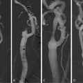
Figure 28.6 illustrates the four main image fusion steps after uploading data from a secondary imaging modality:
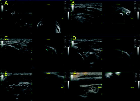
Fig. 28.6
(a–f) Carotid duplex and neck MR fusion imaging
In Fig. 28.6, the carotid bifurcation and calcified plaques were used as intrinsic landmarks for co-registration. Below, we describe in detail the various considerations both for in-vivo and ex-vivo fusions.
3.1 Registration of Landmarks
As previously stated, one of the main challenge with inter-modality fusion of image sets comes from linking recognizable image landmarks through co-registration. Techniques for hardware- and software-based co-registration have been described in depth in the previous sections. Image landmarks, or fiducial markers, chosen for co-registration can be intrinsic or extrinsic to the biological system of interest.
The simplest co-registration techniques with intrinsic landmarks use anatomic features [59]. Anatomy common to a given biological system (e.g., carotid bifurcations) also allows for standardization of in vivo imaging protocols. When extrinsic landmarks are introduced into a biological system, compatibility of the chosen markers between various imaging modalities should be considered. For ex vivo imaging, spatial features of these landmarks aid with identifying spatial orientation within an imaging modality, since the native anatomic orientation (e.g., left–right, anterior–posterior, cranial–caudal) may no longer be present. We encountered these issues in our ex vivo experiments with carotid endarterectomy tissue specimens and have found plastic intravenous 3-way stopcocks to be adequate 3D markers for this system (Fig. 28.7).
 Relationship Between Plaque Echogenicity and Atherosclerosis Biomarkers
 Quantitative Magnetic Resonance Analysis in the Assessment of Cardiac Diseases
 Quantitative Computed Tomography Analysis in the Assessment of Coronary Artery Disease
 Carotid Angioplasty and Stenting
 Segmentation of Carotid Ultrasound Images
 Carotid Plaque Stress Analysis: Issues on Patient-Specific Modeling


Related posts:
Relationship Between Plaque Echogenicity and Atherosclerosis Biomarkers
Quantitative Magnetic Resonance Analysis in the Assessment of Cardiac Diseases
Quantitative Computed Tomography Analysis in the Assessment of Coronary Artery Disease
Carotid Angioplasty and Stenting
Segmentation of Carotid Ultrasound Images
Carotid Plaque Stress Analysis: Issues on Patient-Specific Modeling
Stay updated, free articles. Join our Telegram channel
Full access? Get Clinical Tree
