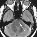
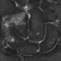
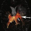
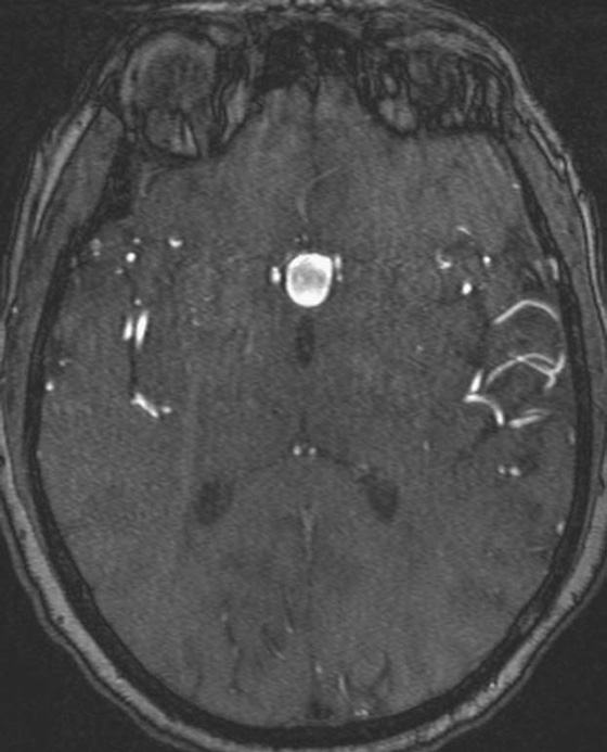
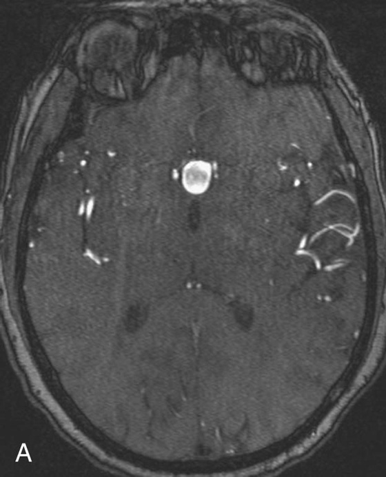
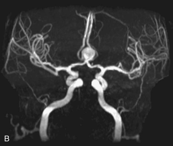
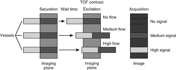
Chapter 11 Scott M. Duncan and Timothy J. Amrhein 1. Does time-of-flight (TOF) imaging use gadolinium-based contrast agents? 2. Why do the arteries have signal but not the veins? 3. What else can be bright on TOF besides flowing protons? 4. What parts of the body are usually imaged with TOF as opposed to contrasted angiography, and why? 5. In how many dimensions can TOF detect flow? FIGURE 1A. Axial time-of-flight (TOF) image. A large high-signal lesion is seen anterior to the third ventricle consistent with an anterior communicating artery aneurysm. FIGURE 1B. Maximum intensity projection (MIP) TOF image of the anterior circulation. Redemonstration of the anterior communicating artery aneurysm. 1. Time-of-flight imaging does not use gadolinium-based contrast agents. 2. The signal from veins is eliminated by applying a saturation band above the desired imaging plane to saturate signal in the veins. 3. TOF has some T1 weighting, so tissues with short T1 times, such as fat, can be bright, similar to inflowing blood. 4. The most common anatomic locations for using TOF are in the circle of Willis and the feet. These areas are susceptible to venous contamination with contrasted angiography, and at the same time, have inflowing spins perpendicular to the axial imaging plane. Venous contamination can be prevented with TOF by applying a saturation band to remove venous signal. 5. TOF imaging can detect flow in just one dimension, in the plane perpendicular to the imaging plane. Saccular anterior communicating artery aneurysm. Time-of-flight (TOF) imaging is an angiographic technique that does not require gadolinium to obtain contrast within the vasculature. With the increased awareness of nephrogenic systemic fibrosis (NSF), this technique has become much more commonly employed when contrast angiography is contraindicated. Even when contrasted angiography can be used, TOF is often used in evaluating the circle of Willis vasculature. In Case 1, the aneurysm is well visualized on the maximum intensity projection (MIP); note that venous flow-related contrast has been eliminated. Much of the physics of TOF angiography is similar to what was discussed in Chapter 10; however, it will also be reviewed in this chapter in order to keep the discussion coherent. TOF angiography is a gradient sequence that optimizes certain parameters to produce bright signal within the vessel while suppressing the nonmobile background tissue. The suppression of background tissues is achieved via signal saturation. The bright signal within the vessel is a result of flow-related enhancement. The suppression of background signal through saturation is performed by applying multiple radiofrequency (RF) pulses in succession to the slice of interest. In TOF imaging, the time to repetition (TR) is so short that protons’ longitudinal magnetization does not completely recover before the next RF pulse. This results in less magnetization available to flip back into the transverse plane with subsequent RF pulses. After several repeated RF pulses, the proton reaches a steady state in which the amount of longitudinal magnetization recovered is equal to the amount flipped into the transverse plane by the next RF pulse.1 This is called “saturation” or “magnetization equilibrium.” (For a more detailed description of this phenomenon, please refer to Chapter 10, with special attention to Figure 1 in that chapter.) Saturation is not an “all-or-nothing” phenomenon, but rather a spectrum. There are multiple variables that affect the degree of saturation, including the flip angle and the TR. Saturation occurs in nonmoving protons. However, a flowing proton that is moving perpendicular to the imaging plane will not have been exposed to the multiple previous RF pulses and will therefore have all of its longitudinal magnetization available when it moves into the imaging plane (i.e., not be saturated) (Fig. 1). Therefore, it will have high signal in comparison with the adjacent saturated stagnant spins. This property is known as flow-related enhancement, and is a time of flight phenomenon; thus time of flight angiography. There are several variables that affect the amount of flow-related enhancement moving spins will have, including TR, slice thickness, velocity, and direction.2 The TR and the flip angle are two important parameters that affect the degree of signal saturation and flow-related enhancement. Shortening the TR results in less time for longitudinal magnetization recovery and less magnetization left for the next pulse. The end result of a short TR is improved signal saturation. Shorter TRs are also beneficial because they mean shorter imaging times and less potential for motion artifact. But shortening the TR does have a drawback. Shorter TRs may not allow enough time for the flowing saturated spins to exit the slice and new unsaturated spins to enter the slice. Thus, shorter TRs can reduce flow-related enhancement. One way to improve flow-related enhancement while maintaining a short TR is to obtain thinner imaging slices. Thinner slices mean shorter distances that the moving protons need to traverse to exit the image slice, which allows the protons within the vessel to be refreshed more quickly. The net result is improved flow-related enhancement. The use of thinner slices comes at the cost of longer imaging time (because more image slices need to be obtained per centimeter of tissue). However, this increased time is offset by the fact that the thinner slices allow for shorter TRs. A typical TR for TOF is 25 to 50 msec with a slice thickness of less than 1 mm. The flip angle of the excitation pulse is another parameter that affects the saturation of stagnant spins. Increasing the flip angle means that more longitudinal magnetization is tipped into the transverse plane, which, for a constant TR, results in less longitudinal magnetization available for the next RF pulse. Therefore, the higher the flip angle, the more magnetization that that does not return to the longitudinal plane, resulting in increased saturation (less signal). The larger the flip angle, the less residual longitudinal magnetization available for the next RF pulse, and the greater the resultant saturation of stationary protons. For TOF imaging, most flip angles range from 45° to 60°. Finally, it should be noted that short TRs and large flip angles in gradient-recalled echo sequences promote T1 weighting (see Chapter 1). Thus, high signal on TOF can be secondary to things other than flow, including fat or subacute blood products. There are several factors that decrease flow-related enhancement. Flow-related dephasing, as was discussed in Chapter 10, is one such factor. Recall that this can be compensated for by using gradient moment nulling or short times to echo (TEs). Typical TEs for TOF angiography are in the magnitude of less than 10 msec. Using short TEs minimizes the need for complex, time-consuming, higher order flow compensation gradients.2 Remember, gradient moment nulling only compensates for first-order flow (constant velocity). The major drawback is increased imaging time that is required to insert extra gradients. Flow velocity is not uniform throughout the lumen of the vessel. For example, the normal laminar flow within a vessel results in higher velocities in the center of the vessel and lower velocities at the periphery. Additionally, there are also microscopic variations in velocity within a vessel due to turbulence and other factors. These small variations in velocity result in dephasing of spins within a single voxel, called intravoxel dephasing. Protons that are within the same voxel and are out of phase with each other will have some of their signal canceled, resulting in decreased signal. Smaller voxel sizes are used to minimize the amount of dephasing, which has the added benefit of improved spatial resolution. However, like everything else in magnetic resonance imaging (MRI), this comes at a cost in the form of longer acquisition times and decreased signal-to-noise ratio. Another limitation to TOF is that it only detects flow in a single plane, perpendicular to the imaged slice. This makes sense because, if a proton is moving in the plane of the slice, it will experience all the repetitive RF pulses applied to that slice and be saturated like stagnant spins. Therefore, the imaging plane should be oriented perpendicular to the direction of flow. Most vasculature is oriented vertically, making the axial plane the best for TOF. By extension, tortuous vessels or vessels than run in a transverse or oblique plane, such as the subclavian or renal arteries and veins, are not well evaluated by the TOF technique. There are a few more limitations to TOF that need to be noted when protocoling or evaluating a study. First, TOF often overestimates the degree of stenosis compared to computed tomography (CT) and conventional angiography. This happens because of intravoxel dephasing of the inflowing blood experiencing magnetic field inhomogeneities. The dephasing of spins leads to less signal within the vessel and an apparent increased stenosis. Turbulent flow also leads to rapid dephasing that cannot be corrected. Thus, areas where there is turbulent flow, such as in regions of stenosis, will have less signal and appear more narrow than they really are.3
Time-of-Flight Imaging
CASE 1

ANSWERS
CASE 1
Diagnosis:
Discussion:
Physics Discussion
Related posts:
![]()
Stay updated, free articles. Join our Telegram channel

Full access? Get Clinical Tree


Imaging