▪
Introduction
Various imaging techniques are used in the assessment of the normal anatomy and pathology of the heart and great vessels. Chest radiography is the most commonly used modality and is often the first imaging test used in the assessment of patients with suspected cardiovascular disorders. Advances in cross-sectional imaging, such as computed tomography (CT) and magnetic resonance imaging (MRI), have enabled dedicated and precise assessment of the morphology and function of the heart. The cardiac chambers, coronary vessels, and valves can all be comprehensively imaged with CT and MRI. With the routine use of retrospective electrocardiographic (ECG) gating or prospective triggering and advanced postprocessing techniques, cardiac structures can be assessed without motion artifacts in multiple planes.
Cardiac Anatomy on Conventional Radiography
The use of conventional posteroanterior and lateral chest radiographs enables the assessment of the normal and abnormal cardiovascular structures that have their interface with the lung. On the posteroanterior radiograph, the structures that form the right margin of the cardiomediastinal silhouette from superior to inferior are the right innominate vein, superior vena cava (SVC), right atrial appendage (RAA), right atrium (RA), and inferior vena cava (IVC; Fig. 3.1A ). The structures that form the left margin of the cardiomediastinal silhouette, from superior to inferior, are the left subclavian artery, aortic knob, aortopulmonary window, main pulmonary artery (MPA), left atrial appendage (LAA), and left ventricle (LV).
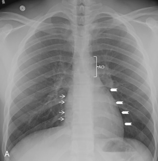
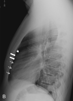
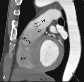
On the lateral radiograph, the anterior margin of the cardiac silhouette is formed by the right ventricle (RV), right ventricular outflow tract (RVOT), and MPA. The upper half of the posterior border of the cardiac silhouette is formed by the left atrium (LA), and the lower half is formed by the posterior wall of the LV. On the lateral radiograph, the right pulmonary artery (RPA) is seen as an oval opacity located immediately anterior to the right upper lobe bronchus, whereas the left pulmonary artery (LPA) is seen above the left upper lobe bronchus (see Fig. 3.1B ).
Technical Factors for Cardiac Imaging and the Imaging Planes
Electrocardiographic Gated Scan
Cardiac motion leads to blurred image borders on CT and MRI. With the use of ECG gating, the image acquisition is timed to the specific phase of the cardiac cycle that provides relatively motionless imaging of the heart, coronary vessels, and proximal aorta. ECG gating can be done retrospectively or prospectively. Retrospective ECG gating is a look-back technique in which images are obtained during the entire cardiac cycle, and the best phases are reconstructed later. In prospective triggering, the data are obtained only during a specific phase of the cardiac cycle that typically is end-diastole, because it is the most motion-free phase of cardiac cycle. The radiation dose to the patient is lower with prospective ECG triggering but, if cine images are required for assessment of left ventricular (LV) wall motion or cardiac valves, retrospective ECG gating is preferred. The images can be reconstructed at specific points during the cardiac cycle for cine imaging. Cine imaging is also required for the assessment of LV wall thickening and determination of quantitative LV functional parameters (e.g., ventricular volumes, stroke volume, ejection fraction).
Cardiac Imaging Planes
Various imaging techniques such as echocardiography, single-photon emission computed tomography (SPECT), positron emission tomography (PET), CT, and MRI have been used to image the heart. To maintain standardization across various techniques, imaging of the heart is displayed along standard orientation planes—short axis, vertical long axis, two chamber, and horizontal long axis, four chamber. These orientation planes also help match various segments of myocardium with their coronary artery supply. The short-axis, horizontal, and vertical long-axis images are obtained at 90 degrees to the long axis of the LV (plane through the apex and center of the mitral valve [MV]).
Although CT images are obtained perpendicular to the long axis of body, four-chamber, three-chamber, and two-chamber planes can be reconstructed from volumetric data due to isotropic resolution of images obtained on newer scanners. The three-dimensional (3D) workstations with cardiac analysis capability can easily produce images in standard planes. These planes can be briefly summarized as below.
Two-Chamber View (Paraseptal View)
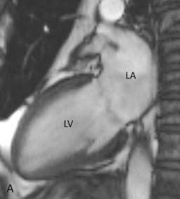
The two-chamber or vertical long axis view is an oblique sagittal plane along the LV cavity axis and is best suited for visualization of the left atrial (LA) and LV cavities, MV, and anterior and inferior walls of the LV ( Fig. 3.2A ).
Three-Chamber View
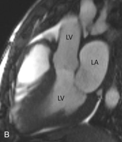
The three-chamber view is an oblique plane that is useful for the evaluation of the mitral and aortic valves, LA and LV cavities, and aortic root. This plane can be obtained manually on multiplanar images by including three points—the center of the MV, the LV apex, and the center of the aortic valve. Other structures that can be evaluated on this plane include the inferolateral and anteroseptal segments of the LV and the posteromedial papillary muscles, along with its chordae tendineae (see Fig. 3.2B ).
Four-Chamber View
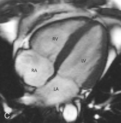
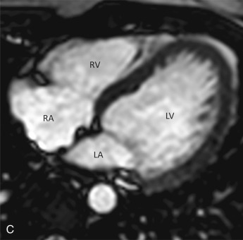
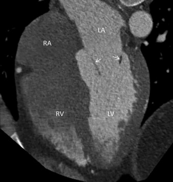
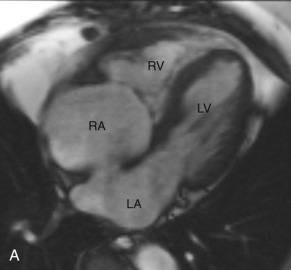
The four-chamber view is an oblique plane that displays all four chambers of the heart. This plane can be manually reproduced on multiplanar images by including the center of the MV, the LV apex, and the center of the tricuspid valve (TV). This plane allows for the assessment of cardiac chamber sizes, evaluation of the MV and TV, and LV inferoseptal and anterolateral segments and LV apex (see Fig. 3.2C ).
Short-Axis Views
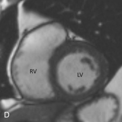
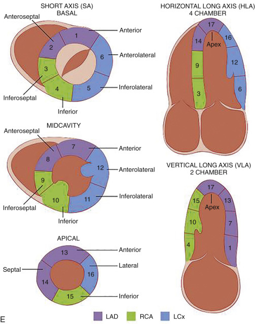
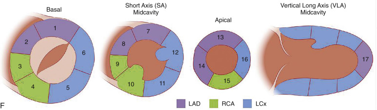
Short-axis views are a stack of oblique planes perpendicular to the long axis of the LV cavity on both the four-chamber and paraseptal long axis views (see Fig. 3.2D ). The LV myocardium can be divided into basal, mid, and apical segments in the short-axis planes. Short-axis views are useful for assessing the LV cavity, regional wall motion, and myocardial anatomy based on the 17-segment model (see Fig. 3.2E ).
Aortic Valve: Short-Axis View
This plane is used for the evaluation of aortic valvular morphology, stenosis, regurgitation, valve prostheses, or masses. The aortic valve short-axis view is a plane that is orthogonal to the long axis of the LV outflow tract (LVOT) and aortic root on the three-chamber view.
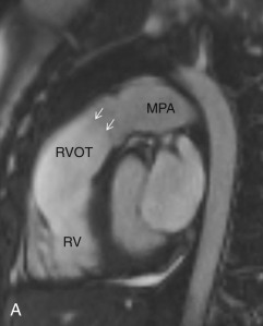
Right Ventricular Inflow-Outflow Plane
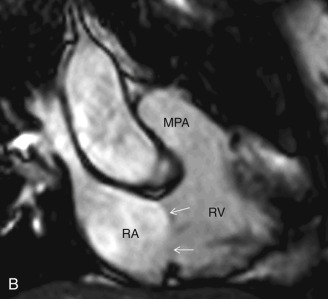
This plane is used for the evaluation of the right side chambers and tricuspid and pulmonic valves. It can be manually reconstructed by joining the center of the TV, RV apex, and center of the pulmonic valve ( Fig. 3.3A–C ).
Bicaval View
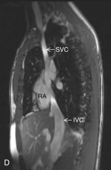
The bicaval view is a standard view on echocardiography that helps visualize the SVC and IVC inflow and superior part of the interatrial septum (IAS), mostly needed for the evaluation and treatment planning of ostium secundum atrial septal defect (ASD; see Fig. 3.3D ). On CT, this view can be manually reconstructed using multiplanar techniques.
Cardiac Chambers
Right Atrium
The RA forms most of the right heart border on a chest radiograph. The venoatrial junctions form the proximal margin of the RA, and the RA terminates at the fibrofatty tissue plane of the atrioventricular (AV) junction. It can be divided into three parts: (1) venous part; (2) appendage; and (3) vestibule. The RA receives the deoxygenated blood from the SVC and IVC, coronary sinus (CS), Thebesian veins, and anterior cardiac vein. It is morphologically larger than the LA but has a thinner wall, measuring up to 2 mm. The distinct feature of the RA is the presence of an internal ridge called the crista terminalis (externally, sulcus terminalis) that divides the smooth-walled venous RA from the rough-walled appendage. It starts from the orifice of the SVC and extends to the anterior aspect of the IVC orifice. The sinoatrial (SA) node, the pacemaker of the heart, is usually located at the junction of the crista terminalis and SVC. The most accurate assessment of laterality of the cardiac chambers for the determination of situs is based on the extent of the pectinate muscle from the AV junction. The vestibule is the smooth muscular rim adjacent to the tricuspid annulus.
Other important anatomic landmarks within the RA that can be assessed by cross-sectional imaging include the cavotricuspid isthmus and triangle of Koch. The cavotricuspid isthmus is best seen on a coronal view and represents the area between the tricuspid annulus and IVC. This area is a good target for radiofrequency ablation because it aids in the maintenance of reentrant circuits. The triangle of Koch represents the anatomic location of the AV node; it is defined as the area between the tendon of Todaro (fibrous extension from the eustachian valve), septal leaflet of the TV, and orifice of the CS. The morphologic features of the LA and RA are highlighted in Table 3.1 .
| RIGHT ATRIUM | LEFT ATRIUM |
|---|---|
|
|
Right Ventricle
The RV is the most anterior chamber of the heart. It has more complex geometry and orientation than the LV. Anatomically, it can be divided into three parts: (1) the inlet, consisting of the TV, chordae tendineae, and papillary muscles; (2) the trabeculated apical myocardium; and (3) the smooth-walled infundibulum–conus arteriosus (also referred to as the RVOT). As compared to the LV, the RV has a thinner wall (measuring ≈3–4 mm) but with significantly more trabeculations. Another distinct feature of the RV is the presence of the moderator band, which is a muscular extension from interventricular septum to the RV free wall, near the RV apex. The moderator band prevents the overdistention of the ventricle and contains the right bundle branch. The RV has three, or sometimes more, papillary muscles (anterior, posterior, and septal) that attach to the respective leaflets of the TV (anterior, posterior, and septal). The anterior papillary muscle is the largest and arises from the anterior free wall of the RV. The septal papillary muscle is the least consistent papillary muscle of the RV and often cannot be distinguished from the ventricular wall. The pulmonary artery arises from the conus of the RV and is positioned anterior and to the left of the aorta. Another feature that helps identify the morphologic RV is that the muscular infundibulum separates the tricuspid and pulmonary valves, with no fibrous continuity among them ( Fig. 3.4 ). The morphologic features of the LV and RV are highlighted in Table 3.2 .
| RIGHT VENTRICLE | LEFT VENTRICLE |
|---|---|
|
|
Left Atrium
The LA is the most posterior chamber of the heart and is located superior to the RA due to the obliquity of the IAS. It is separated from the RA by the presence of the IAS, which is a thin structure that may be difficult to assess accurately on MRI. Higher spatial resolution of newer multidetector CT (MDCT) scanners allows improved evaluation of the IAS, especially when there is fat deposition in it. It is important to distinguish relatively benign lipomatous hypertrophy of IAS from other fat-containing cardiac masses. The lipomatous hypertrophy of IAS is associated with septal thickening that is usually more than 1.5 cm thick and spares the fossa ovalis, giving rise to the typical dumbbell-hourglass appearance. In-depth knowledge of the LA and its appendage is important because catheter ablation of the LA is being increasingly used for patients with atrial fibrillation.
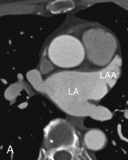
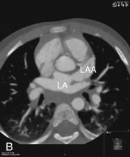
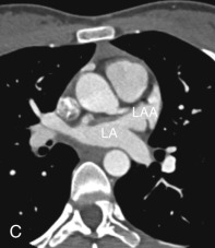
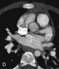
The transverse pericardial sinus and aortic root lie immediately anterior to the LA, whereas tracheal bifurcation, the esophagus, and the descending thoracic aorta lie immediately posterior to the pericardium lining the outside of the posterior wall of the LA. The wall of the LA is muscular but is smooth on its internal aspect. The wall thickness of the LA varies but is thinnest at the anterior aspect, just behind the aortic root, which is considered the unprotected area and is at a higher risk of perforation. Intervention electrophysiologists are especially interested in the posterior wall of the LA and the relationship of the esophagus relative to the pulmonary vein (PV) orifices due to possible esophageal injury associated with ablation procedures. The LA has a finger-like appendage arising from the anterolateral aspect of the main body, adjacent to the left superior PVs (LSPVs). The main body of the LA can be divided anatomically into the pulmonary venous part, septal part, and vestibule—the portion of the LA adjacent to the MV orifice.
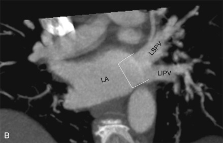
The clinical significance of LA size has been the topic of various studies; it has been shown that an increase in LA size correlates with poor patient prognosis in patients with an acute myocardial infarction, and higher LA size correlates with a higher chance of atrial fibrillation in older populations. The size of the LA is measured at end-ventricular systole, and the LA area and volume can be calculated on 3D workstations by manually drawing the outline along the endocardial border of the LA at the MV and in its superior aspect. The workstation interpolates the endocardial border in between these lines and should exclude PVs and the LAA. The reference limits for the area of the LA are highlighted in Table 3.3 .
| LIMIT (cm 2 ) | SIGNIFICANCE OF FINDINGS |
|---|---|
| <20 | Normal |
| 20–30 | Mildly abnormal |
| 30–40 | Moderately abnormal |
| >40 | Severely abnormal |
Left Atrial Appendage
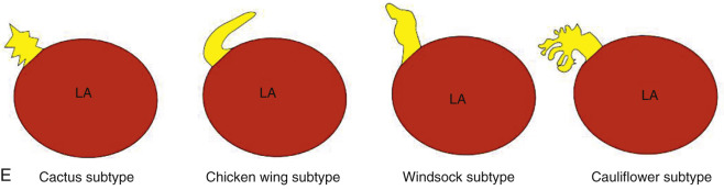
The LAA is an embryologically distinct part of the LA that arises from the trabeculated primitive LA, as compared to the smooth-walled LA that arises from the pulmonary venous bud. The LAA arises from the superolateral part of the LA and forms part of the left heart border on radiography. The LAA is closely related to the pulmonary trunk superiorly; inferiorly, it is adjacent to the left coronary artery (LCA) in the AV groove and free wall of the LV. Usually, the LAA is directed anterosuperiorly. The LAA is one of the common anatomic sites in the heart to harbor thrombus that may be responsible for an embolic phenomenon. Internally, the LAA contains the pectinate muscles that increase in thickness with age; they are more than 1 mm in thickness in more than 90% of those older than 20 years. These pectinate muscles may be mistaken for thrombus on cross-sectional imaging and echocardiography. Anatomically, the LAA can be further divided into the (1) ostium, (2) neck, and (3) body. Based on its gross appearance, the LAA has been divided into four shape types—cactus, chicken wing, wind sock, and cauliflower ( Fig. 3.5 ). Overall, the chicken wing is the most common subtype and is also associated with the least incidence of embolism in patients with LAA thrombus. The knowledge of various anatomic parameters and their variations is important because it may help guide interventional procedures aimed at closing the LAA to prevent thromboembolism. As compared to the LAA, the RAA has a wider ostium and is more triangular and pyramidal in shape. This distinction may be important in patients with complex congenital heart disease for the determination of situs.
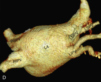
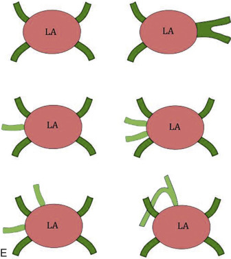
Pulmonary Veins
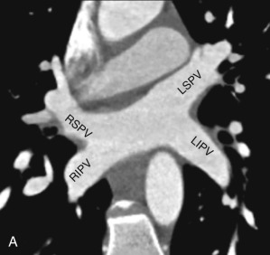
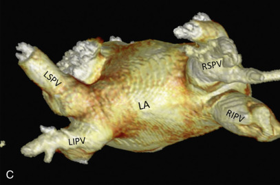
Normally, there are four PVs, two on each side, that carry oxygenated blood from either lung to the LA. The knowledge of PV anatomy and its variations is important because the variations in drainage may be symptomatic, and PV ostia are commonly targeted for catheter ablation therapy. The normal configuration of PVs and its ostia is seen in 60% to 70% of the population ( Fig. 3.6A ). The variations in left side PVs are more common, with the most common variation being the convergence of superior and inferior PVs to drain via a common trunk (short or long; see Fig. 3.6B and C ). Variations of the right pulmonary venous system are less common; these include the following: (1) one accessory right middle PV (see Fig .3.6D ); (2) two accessory right middle PVs; and (3) one accessory right middle PV and one accessory right upper PV (see Fig. 3.6E ).
The muscular layer of the LA extends into the wall of the distal PVs. The length of extension of the atrial myocardium correlates with the extension of the pericardium along the PVs. The LSPV has the longest intrapericardial course (11–13 mm) and is the focus of atrial fibrillation in most patients. The LSPV is separated from the ostium of the LAA by the presence of a fold of the lateral atrial wall, known as the left lateral ridge, left tinea terminalis, or coumadin ridge . When prominent, it can be mistaken for a thrombus or mass. It is also important to recognize the anomalous drainage of PVs because it may go undetected until adulthood, when it may present with progressive shortness of breath. Pulmonary venous drainage is defined as anomalous if the PV is draining into any vascular structure other than the LA. If at least one PV drains into the LA, it is called a partial anomalous pulmonary venous connection ; otherwise, it is called total anomalous pulmonary venous drainage . On CT imaging, PV imaging can be obtained without the use of ECG gating but, if CT is being done for radiofrequency ablation planning, ECG gating is preferable (if low-dose acquisition is available), because it helps reproduce accurate epicardial and endoluminal volume-rendered images.
Left Ventricle
The LV is the outflow chamber of the heart that pumps the oxygenated blood into the systemic circulation. With respect to the RV, it lies posteriorly and to the left. The LV has the thickest myocardium among the cardiac chambers, and its inner surface can be distinguished from the RV by the presence of fine trabeculae carneae, giving it a relatively smooth appearance. Fibrous continuity between the mitral and aortic valves also helps distinguish the LV from the RV. Another characteristic feature of the LV is the presence of anterior (lateral) and posterior (medial) papillary muscles, which are attached only to the free wall of the LV. Each papillary muscle receives chordae tendineae from either MV leaflet, which prevents regurgitation of blood into the LA during ventricular systole. The anterolateral papillary muscle has a richer blood supply, derived from the branches of the left anterior descending artery (LAD) and left circumflex artery (LCx). The posteromedial papillary muscle is more prone to necrosis owing to the relatively poor blood supply from the LCx and posterior descending artery (PDA).
Cardiac Valves
Improvement in the temporal and spatial resolutions of CT and MRI has enabled noninvasive evaluation of cardiac valvular structure and function. The valves that are commonly assessed by imaging include the aortic, mitral, pulmonic, and tricuspid valves.
Tricuspid Valve
The TV is composed of three leaflets and separates the RA from the RV. The TV apparatus consists of leaflets, annulus, commissures, chordae tendineae, and papillary muscles. The leaflets are labeled as anterior, posterior, and septal and are connected to a fibrous ring, known as the annulus. The three cusps are continuous to each other at their bases, forming the commissures. Due to lower right side pressure, the TV leaflets are usually thinner than the MV leaflets. The chordae tendineae attach to the free margin of the TV leaflets and connect them to the two papillary muscles. One distinguishing feature of the TV is the presence of the crista supraventricularis, which is a muscular ridge separating the TV from the pulmonic valve ( Fig. 3.7 ).
Pulmonic Valve
The pulmonic valve is a tricuspid semilunar valve that separates the RVOT from the pulmonary artery. Its three cusps (or leaflets) are labeled as right, left, and anterior. Anatomically, the pulmonic valve is located superior, anterior, and to the left of the aortic valve ( Fig. 3.8 ). The lack of fibrous continuity with the TV also helps distinguish the pulmonic valve from the aortic valve. The central part of the valve leaflet has a thick central focus, also known as the nodulus of the semilunar valve , and a thin lateral free edge margin, known as the lunula of the semilunar valve . Normally, the pulmonic valve measures 2.0 cm 2 /m 2 of body surface area.