53CHAPTER 5
Imaging for SRS and SBRT
In stereotactic radiosurgery (SRS) and stereotactic body radiation therapy (SBRT), relatively small tumor targets are treated to high, ablative doses with minimal treatment margins. Therefore, geometric accuracy, in planning and treatment, is of the highest importance, to avoid geographic miss of the tumor or overdosing of adjacent normal tissues. Imaging studies of the patient must be of high quality and high resolution for this reason.
The imaging process often begins with diagnostic imaging studies of the patient, in which the target location is determined and the need for SRS/SBRT is first identified (Figure 5.1). Then, after application of an appropriate immobilization technique (see Chapter 4), a treatment planning imaging study, generally a high-resolution CT scan, is performed with the patient in treatment position. Depending on the treatment site, additional studies may be performed with/without contrast, or with the application of four-dimensional (4D) imaging. The imaging study should be carefully reviewed by the physician before being used for treatment planning. Finally, the isocenter may be identified and marked on the patient.
Additional studies may then be done in multiple imaging modalities to aid in localizing disease, or to exclude certain tissues at risk from the target volume. Registration of the image volumes (rigid or deformable) is performed, either at the treatment planning workstation or in a separate application. Again, the image fusion must be carefully reviewed before proceeding with treatment planning.
After the treatment plans have been reviewed and approved, and the patient is set up for treatment, imaging is performed at the treatment machine to localize the target for treatment. The imaging may be repeated after an initial shift, particularly if the shift is large, to confirm that the shift has been performed in the correct direction. Imaging may also be used throughout treatment to confirm that the patient has not moved from his or her initial setup.
Finally, imaging will be performed at intervals after the end of treatment to evaluate the results of the therapy and to screen for any new recurrences of disease. Care must be taken to distinguish between normal radiographic changes after treatment and recurrence of disease.
3D AND 4D CT IMAGING
Radiological imaging is a key step in the SRS/SBRT treatment planning process. To achieve the goal that potent radiation dose is precisely delivered to the target while sparing the organs at risk (OARs) via rapid dose falloff, accuracy of target delineation is essential. Today, the radiation therapy (RT) process is mainly CT-based because it provides detailed information about a patient’s anatomy as well as the tissue electron density data that are needed for accurate dose calculation. For certain protocols, abdominal compression may be preferred to reduce the organ motion. Metallic objects should be removed before the scan. The CT slice thickness should be less than 3 mm, and the scan length should be 5 to 10 cm extended beyond the target in both superior and inferior directions (15 cm if a noncoplanar plan is going to be used). Relevant OARs should also be fully covered by the CT scan for an accurate dose–volume analysis. One should also note that, if there is cutoff in the CT scan, most treatment planning systems (TPS) do not allow beams passing through that region. If a contrast scan is needed, a planning CT without contrast should be acquired first, because the high CT numbers of contrast agents may lead to incorrect dose calculation (1). For patients with metallic objects in the body (e.g., tooth filling, prosthesis), significant metal artifacts can present in the CT image as dark and bright streaks around the metal objects in the axial plane. To improve the dose calculation accuracy, these artifacts can be contoured and assigned with a proper CT value (Figure 5.2). Metal artifact reduction algorithms are also available (2). During the treatment planning, the beam should avoid entering from the metallic object side if possible.
54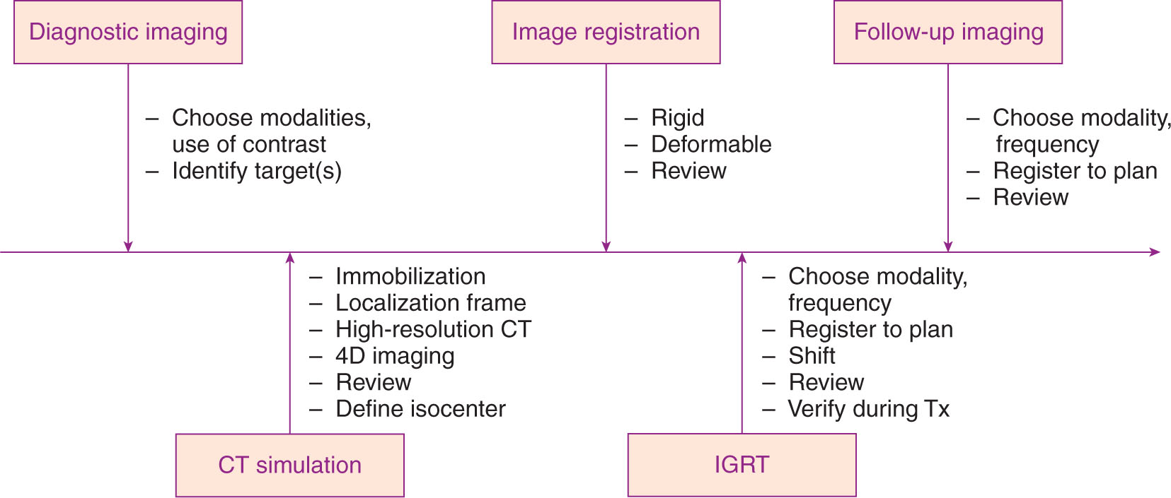
FIGURE 5.1 Process map of imaging for radiosurgery.
4D, four-dimensional; IGRT, image-guided radiation therapy; Tx, treatment.
When treating a moving target, for example, SBRT of lung, liver, pancreas, or abdomen area, traditional three-dimensional (3D) CT often presents large motion artifacts, which adversely affect the contouring. A 4D CT scan is needed in these situations. 4D CT imaging typically uses cine mode, which repeatedly scans each section of interest along the patient’s long axis for a period slightly longer than one respiratory cycle. Multiple images are generated for each section and tagged with the corresponding respiratory signals, which typically come from an external tracking device such as Real-Time Position Management (RPM) system or abdominal belt. The images of all sections are sorted retrospectively on the basis of the corresponding breathing signals, and multiple 3D CT sets are obtained, each corresponding to a particular breathing phase (Figure 5.3). 4D CT can dramatically reduce the motion artifacts and gives target motion information as well. During treatment planning, the planning target volume (PTV) can be created by adding a universal 5-mm margin to the so-called internal target volume (ITV), which is defined as the combined volume of the target at all phases of breathing cycle (or selected phases if gating technique is preferred). Most CT scanners or TPS now have functions that support generation of an ITV automatically. For example, for solid tumors (high CT density), a maximum intensity projection (MIP) function can be used to create an image in which each pixel is assigned a value equal to the maximum value among all phases for that particular location. By doing this, the new “target” volume in the MIP image is equivalent to the ITV. Similarly, a minimum intensity projection (MinIP) function can be used for targets with low density (compared with surrounding tissues), such as lesions in the liver.
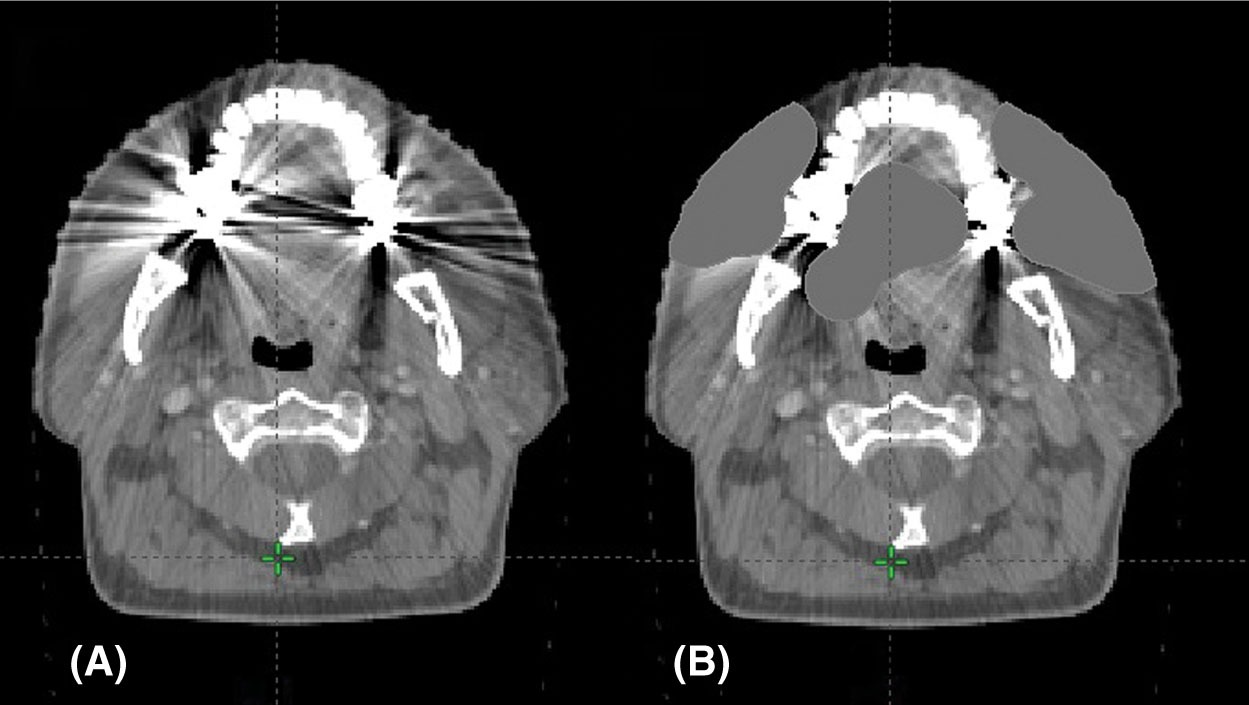
FIGURE 5.2 CT artifact from dental fillings: (A) original scan and (B) scan with density correction applied.
55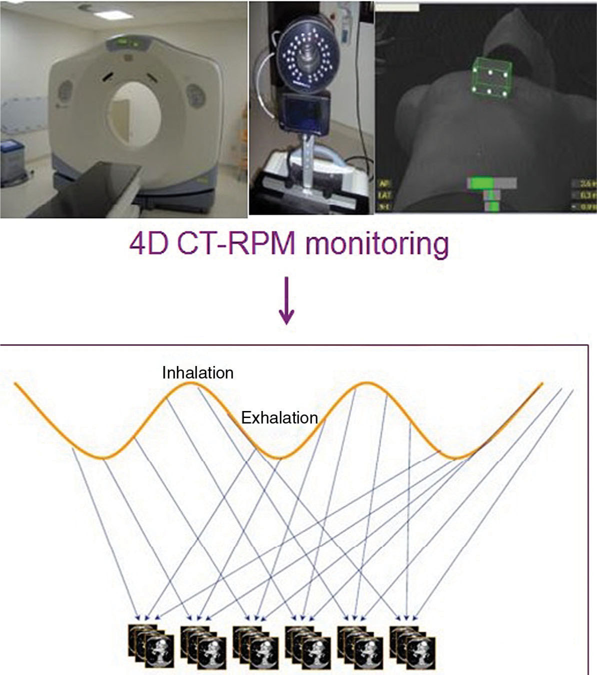
FIGURE 5.3 Sorting CT images to generate a 4D CT. Cine CT images are acquired and synchronized to breathing signal. Retrospective sorting generates full CT images at each phase of the breathing cycle.
4D, four-dimensional; RPM, real-time position management.
3D AND 4D PET
Positron emission tomography (PET) imaging is a technique to image the radioactive tracer distribution in a patient. Among many types of radioactive tracers, 18F-fluorodeoxyglucose (FDG), a radiolabeled analog of glucose, is most commonly used in the clinic. Because glucose uptake is increased in many malignancies, 18F-FDG PET is a sensitive method to detect lesions, to stage disease, and to monitor the radiation response in RT (3). For general PET procedures, 18F-FDG radioactive pharmaceutical is injected into a patient first, with typical dose ranging from 370 to 740 MBq for an adult. The patient should be seated in a quiet room for at least 45 minutes before data acquisition. A full-body PET scan can take more than 30 minutes. The spatial resolution of PET imaging is significantly worse than that of CT imaging. The typical slice thickness is about 3.75 mm, and in-plane pixel size is 5 to 8 mm. PET scanners are designed to measure the in vivo radioactivity concentration (kBq/mL), which is directly linked to the FDG concentration. Most of the time, however, it is the relative tissue uptake of FDG that is of interest. The two most significant sources of variation that occur in practice are the amount of injected FDG and the patient size. To compensate for these variations, the standardized uptake value (SUV) is commonly used as a relative measure of FDG uptake. The basic expression for SUV is where r is the radioactivity concentration (kBq/mL) measured by the PET scanner within a region of interest (ROI), a‘ is the decay-corrected amount of injected radiolabeled FDG (MBq), and w is the weight of the patient (kg), which is used as a surrogate for a distribution volume of tracer.
![]()
56PET imaging itself does not contain sufficient anatomical information, so it must be registered to other images (e.g., CT) to determine the location and extent of malignancies. Although techniques for registration of images obtained from separate PET and CT scanners have been available for many years, having PET and CT imaging capabilities in a single device has many apparent advantages: It provides reliable hardware-based registration and the CT also provides information for PET attenuation correction (4). Combined PET/CT devices providing both the metabolic information and the anatomical information in a single examination are clearly more accurate and more efficient in evaluating patients with known or suspected malignancies than the information obtained from either PET or CT alone or the results obtained from PET and CT separately but interpreted side by side.
During the treatment planning process, the malignancies often show high intensity (high SUVs) in the fused PET/CT image, and these values can be used to guide the delineation of the tumor volume. However, many factors affect the SUV, for example, dose infiltration, time of imaging after 18F-FDG administration, type of reconstruction algorithms, type of attenuation maps, size of the ROI, changes in uptake by organs other than the tumor, and methods of analysis. Sometimes there may also be misregistration between PET and CT, mainly because of patient motion between PET scan and CT scan. One should always examine the accuracy of the registration before using it for treatment planning.
Respiratory motion results in inaccurate localization of lesions at the base and periphery of the lungs, in the dome of the liver, or near any lung–soft tissue interface and may result in spurious SUV determinations. Motion correction or respiratory gating is recommended when available. Similar to 4D CT, 4D PET is a technique for respiratory-correlated imaging. A respiratory device (e.g., RPM) is used to trace the patient breathing and send signals to the scanner. The respiratory movement is categorized into several phase bins. Once the PET scanner receives a trigger from the respiratory device (typically at the end of inspiration), it starts to prospectively collect data (coincidence events) into the corresponding bins on the basis of the time stamp in each respiratory cycle, and reconstruct the data in each bin into a 3D image when the acquisition is done. Although PET and CT can be spatially registered by the hardware, there could be large mismatch between 4D CT and 4D PET in the temporal domain when an irregular respiratory pattern occurs.
3D AND 4D MR IMAGING
MR images are formed from signals induced by mainly 1H nuclei (spin ½) in water (lipids) when they precess coherently in a strong magnetic field. Unlike CT scanning that uses ionizing radiation, the advantage of MRI is that it uses only low-amplitude nonionizing radio waves. But more importantly, MRI also provides superior soft-tissue contrast. It has been routinely used in RT for brain, head and neck, spine, prostate, and other SRS/SBRT treatments.
In MRI, different techniques have been developed over the years to visualize different tissue properties, such as dynamic contrast-enhanced (DCE) MRI, diffusion tensor imaging, MR angiography (MRA), and MR spectroscopy. The MR image quality (tissue contrast, spatial resolution) is directly affected by the pulse sequence used, which has a number of parameters, such as time to echo (TE), time to repetition (TR), flip angle, and inversion pulses. The sequences can be broadly grouped as spin echo sequences, inversion recovery sequences, gradient echo sequences, diffusion-weighted sequences, saturation recovery sequences, echo-planar pulse sequences, and spiral pulse sequences. However, for nonradiologists, a simplified way of grouping is by weighting (T1 or T2) and additional features (e.g., fat suppressed or gadolinium enhanced). T1-weighted MR imaging is often used with gadolinium for enhancing tumors, whereas T2-weighted imaging is used for nonenhancing lesions (e.g., low-grade gliomas). Multiple sequences of contrast-enhanced T1- or T2-weighted imaging are often used together in a single examination to provide complementary information (Figure 5.4). For brain SRS, the MRI should have a resolution at least 1.5 mm in all directions.
In radiosurgery, the MR images are often fused with CT images to delineate the tumor volume. For intracranial or spine SRS, a local rigid registration may be sufficient. For other regions like prostate, a deformable registration may be more appropriate. MRI can also be used as stand-alone imaging in RT. The main advantage of MRI-based planning is that it removes systematic errors that may occur because of CT–MRI image registration. However, it requires a link from MR image intensity to electron density. One approach is to use a CT atlas and nonrigid registration to transfer CT information to the patient’s MR image. The main MRI manufacturers are currently pursuing packages to produce electron density estimates for RT applications at the MR console. Although still limited to a small range of applications, this development has enabled MR-only workflows in prostate RT (5) (Figure 5.5).
57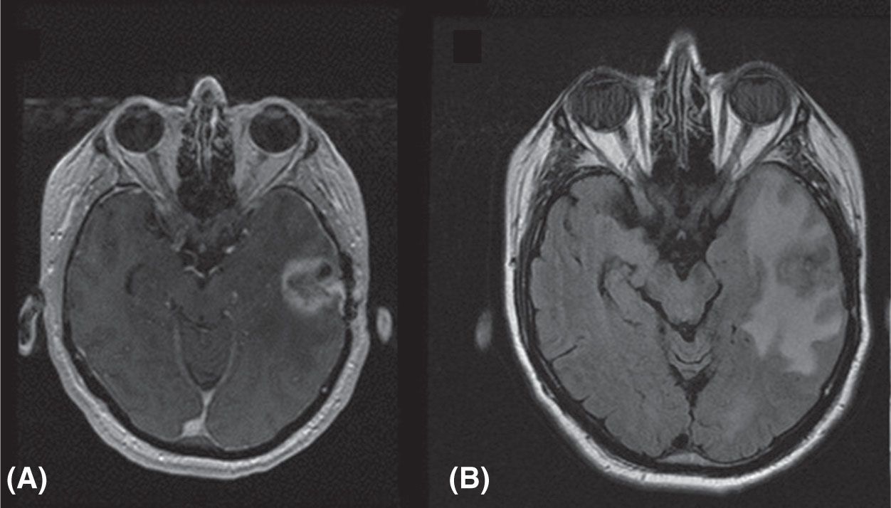
FIGURE 5.4 MRI images of metastatic prostate cancer patient: (A) T1-weighted image with contrast and (B) T2-weighted FLAIR image.
FLAIR, fluid-attenuated inversion recovery.
Source: Courtesy of Dr. J. Engh, University of Pittsburgh Medical Center.
One major challenge of using MRI in SRS/SBRT is the potential spatial distortion of the image because of inhomogeneities of magnetic field, gradient field nonlinearity, and patient-specific magnetic susceptibility distribution. Although considerable research efforts have been made, the distortion cannot be entirely eliminated. For example, because of air–tissue interfaces, there may be displacements of 1 to 2 mm over very short distances from the interface (<1 cm). Motion artifact is another problem for MRI, because a high-resolution 3D MRI scan can take up to 10 minutes. A number of gating techniques can be used to produce diagnostic MR images in the presence of cardiac and respiratory motion. 4D MRI has also been developed to get a full picture of motion. MRI can generate time-resolved images by using prospective and retrospective gating techniques that average data over several motion cycles. These MR images will represent a mean motion state and the image quality may be compromised in case of irregular motion. The recent advent of parallel imaging and sparse sampling techniques has allowed faster data acquisition, and it is now possible to acquire volumetric data with high temporal resolution (6).
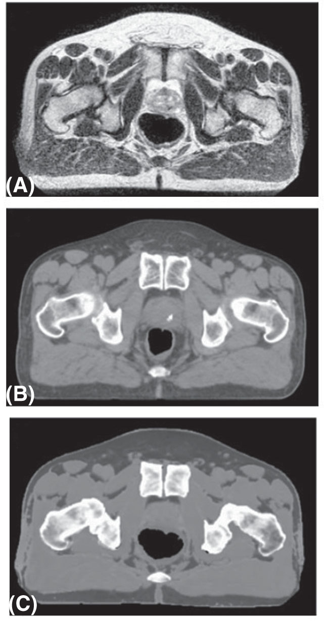
FIGURE 5.5 Synthetic CT imaging from MR of the prostate: (A) original T2-weighted MR image; (B) CT image; and (C) synthetic CT image generated from image.
Source: Adapted from Kim J, Garbarino K, Schultz L, et al. Dosimetric evaluation of synthetic CT relative to bulk density assignment-based magnetic resonance-only approaches for prostate radiotherapy. Radiat Oncol. 2015;10:239. doi: 10.1186/s13014-015-0549-7
58IMAGING FOR GAMMA KNIFE
Before Gamma Knife treatment, the patient is imaged using either MRI or CT or both, with a fiducial box attached to the patient’s stereotactic frame. The lesions, skull boundary, and fiducials are all identified in the image and are used to design the radiosurgery treatment plan. During treatment, the patient with the stereotactic frame is locked to the treatment couch, and the plan parameters with respect to the frame are transferred to the Gamma Knife treatment unit so that the beams can be precisely delivered to the target.
The newer Gamma Knife model Icon integrates a stereotactic cone-beam CT (CBCT) system into the machine, which makes it possible to perform CT-based dose calculation and frameless radiosurgery (7). The CBCT scans a patient in treatment position and coregisters it with the patient’s MR image. The CBCT voxel size is 0.5 × 0.5 × 0.5 mm3, and stereotactic coordinates are assigned to each voxel. The CBCT provides information for dose calculation for treatment planning and setup verification for treatment. The Icon unit is also equipped with an infrared camera to monitor the patient motion in real time, and has the ability to stop the treatment when the patient’s head moves out of the preset limits. Typical workflow for Gamma Knife Icon is as follows: Day 1, patient simulation—acquisition of planning MRI/CBCT, making mask, registering MRI and CBCT images, and preparing treatment plan; and Day 2, treatment delivery—setting up patient, acquisition of stereotactic CBCT images, registering CBCT images, revising coordinates of each shot, reviewing updated dose–volume histogram (DVH), and delivery of treatment.
IMAGE REGISTRATION IN SRS/SBRT
In SRS/SBRT, multiple image sets are often used to better define the target volume. To use multiple image sets in treatment planning, it is necessary to have an accurate way to map the voxels in one image to the coordinates of a reference image set for planning. This is especially challenging when the images are from different modalities, or the patient position in the reference image is different from that in the registered image.
Image registration is used throughout the process of planning, treatment, and follow-up. Initial diagnostic image sets are often fused to the treatment planning scan to assist in target definition. Registration of the treatment planning scan to a reference “atlas” data set may be used to assist in contouring multiple organs automatically (8). Image registration is used in daily image-guided radiation therapy (IGRT) for SRS patients, and may be repeated several times throughout each fraction to track patient motion. In many systems, like those in robotic radiosurgery, this process is completely automated (9). Finally, follow-up images taken after treatment may be fused to the treatment plan, to correlate radiographic changes after treatment with the delivered treatment dose.
Image registration may be performed using automated registration functions, manual registration, or a combination of both. Often, an automatic registration function is applied first, followed by small manual adjustments. The final evaluation of the registration is usually performed by visual inspection, particularly focusing on the region of the target and immediately adjacent OARs.
Registrations, automated or manual, are most accurate between similar data sets, where the patient is in treatment position, and the image slices are in coincident (typically axial) planes and of similar resolution. In less similar data sets, it is important to focus attention on the target region, accepting that the registration may not be as reliable in areas well away from the target. Most image registration software allows the user to manually define a volume of interest in which to apply the registration, excluding information away from the target that may reduce the accuracy of the registration.
The process of automated image registration consists of three components: a similarity metric, a transformation function from one image set to another, and an optimization process. The optimization is used to find the transformation parameters that maximize the value of the similarity metric. Similarity metrics may include geometry-based functions, for example, the sum of squared differences from structures derived in each image, or intensity-based functions.
In monomodality registration (e.g., CT to CT), one may use intensity-based metrics, such as sum of squared differences, or the variance of a ratio of the two images (e.g., when comparing CT with CBCT, where the Hounsfield unit numbers are 59slightly different). Such methods may be susceptible to small regions of large contrast difference, for example, if air or contrast agent is present in one image but not in the other.
In multiple modality registration (e.g., MR to CT), the relative intensities of pixels in the two images are not similar, so some form of remapping of image intensities, or correlation of intensities between the two images, is required.
The simplest transformation function is a rigid transformation between one image and the other, including 6 degrees of freedom (translations and rotations). In more distensible geometries, deformable registration may be applied, with up to 3N degrees of freedom, where N is the number of voxels in the image. Commercial deformable registration software generally includes limits on the available deformations to avoid discontinuous or nonphysical deformations.
In practice, a rigid registration is generally performed and saved first, followed by a separate, nonrigid registration if necessary. The image registration request should include detailed information, including the images to be registered (including identification of the primary image), the ROI, and the requirement for rigid or deformable registration.
Careful evaluation of the registration should be performed by the physician, including evaluation of anatomical points or implanted fiducials near the target that may be well localized in three dimensions. In the cranium, a number of anatomical structures may be used for general assessment of image fusion, including the orbits, sella turcica, tentorium, ventricles, or patterns of sulci.
In image registration for IGRT, only rigid registration is typically performed, because deformations cannot be applied to the patient being treated. Registration is often done in stages, starting with a broad registration of the bony anatomy, followed by a more focused registration of soft tissue or implanted fiducials near the target volume. Registration may include only translations, or include one to three rotational axes, depending on the capabilities of the treatment couch.
IMAGING FOR TREATMENT SETUP AND VERIFICATION
For hypofractionated and single fraction SRS/SBRT techniques, accurate targeting has increased importance relative to conventional fractionation, both to achieve the desired efficacy and to limit toxicity. Without image guidance, required margins are unacceptable for SRS/SBRT. In prostate, for example, the margin required without image guidance is greater than 10 mm, whereas daily IGRT reduces the margin to less than 5 mm (10). The American Association of Physicists in Medicine (AAPM) report of Task Group 101 recommends image guidance for SBRT to localize targets with high confidence (11). The gold standard for targeting is radiographic imaging prior to treatment; however, a number of new technologies have been developed that do not rely on ionizing radiation. These technologies include electromagnetic transponder tracking, optical surface monitoring, and MRI. These technologies can be used to supplement radiographic imaging and to monitor target position during radiation delivery.
X-Ray Image Guidance
X-ray imaging is the most extensively used image guidance modality and is the gold standard for patient positioning. X-ray image guidance systems can be divided into two types: on-board imaging and room-fixed imaging (12).
On-board image guidance system consists of a kilovoltage (kV) x-ray source and a flat panel detector mounted to a C-arm linear accelerator gantry (Figure 5.6). The imaging axis is typically perpendicular to the axis of the treatment beam. The system can be used to obtain planar images from stationary gantry positions, typically orthogonal pairs, or to construct a CBCT volumetric image from multiple projections. On-board imagers and CBCT have been extensively described in a review by De Los Santos et al. (13). The x-ray source and the imager undergo small deviations from the 60intended position as the gantry rotates, producing small misalignments with the treatment isocenter. These motions are systematic and can be measured and used to correct the image position, either by adjusting the imager position prior to image acquisition or by correcting the image position in software. Both methods result in submillimeter accuracy (14) and, for intracranial applications, have accuracy equivalent to a stereotactic head frame (15). For paraspinal lesions, Chang et al. demonstrated that daily image guidance provides ~1.5-mm accuracy, whereas stereotactic body fixation alone achieved 2- to 3-mm accuracy.
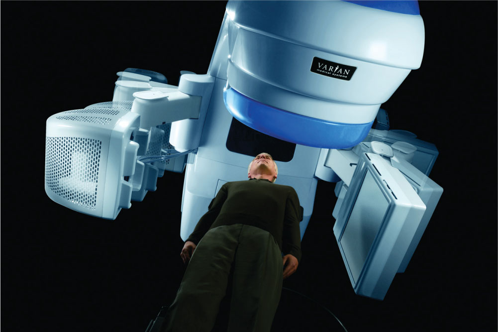
FIGURE 5.6 Gantry-mounted kV imaging system (Varian OBI) capable of planar kV imaging and cone-beam CT.
Source: Image courtesy of Varian Medical Systems, Inc. All rights reserved.
Image guidance using orthogonal images can use either bony anatomy or implanted fiducials for target localization. In SBRT sites such as prostate, lung, and liver, bony anatomy is a poor surrogate for target position and thus fiducials are necessary for accurate targeting. Cone-beam imaging should be considered as a supplement to orthogonal imaging when the location and shape of OARs is variable, such as the bladder and rectum (16). When bony anatomy is not a good surrogate for target position and implanted fiducials are not available, orthogonal imaging should not be used without CBCT.
On-board imaging systems can be used to monitor target position during treatment. At least one commercial system (Varian Medical Systems, Milpitas, California) has the capability to acquire kV images during treatment at intervals defined by respiratory cycle, gantry angle, monitor units, or time. However, this approach has two caveats. First, only a single projection is obtained at each trigger and thus provides only a two-dimensional assessment of position. Second, the collision-free zone of the imaging system is limited to a narrow range of table angles near 0° (IEC scale).
Room-Fixed kV Imaging
A room-fixed image guidance system is made up of two x-ray sources and flat panel detectors mounted such that the x-ray source central axes intersect at isocenter at an angle sufficient to permit stereoscopic visualization of the target anatomy (Figure 5.7) (17). Room-fixed guidance systems are the primary image guidance system for robotic radiation therapy systems (18) and either can provide primary image guidance for C-arm RT linacs (19) or are used as a supplement to on-board image guidance. Stereoscopic systems are capable of submillimeter accuracy (20), which is comparable to that achieved with cranial stereotactic frame (21). An advantage of stereoscopic image guidance systems is that they can be used for intrafraction position verification over a wide range of gantry and table positions (22). For table angles near 0°, room-fixed systems have a stereoscopic view and thus can assess positions in three dimensions. However, for some table–gantry combinations, one of the imagers is obstructed and the view is limited to a single projection and thus two-dimensional, rather than 3D, position assessment. Similar to planar images obtained with an on-board imaging system, room-fixed systems are most accurate when bony anatomy or implanted fiducials are a good surrogate for the target position.
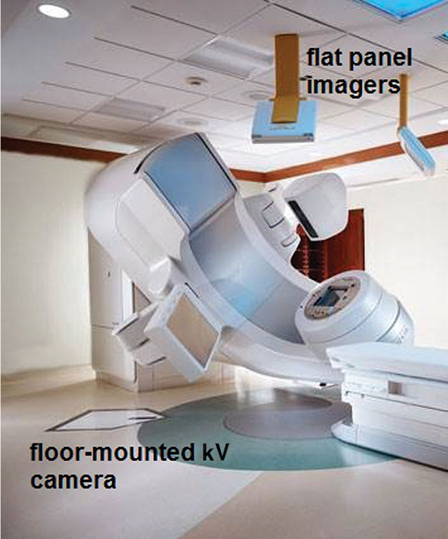
FIGURE 5.7 Room-mounted kV imaging system (Brainlab ExacTrac) with two cross-firing x-ray cameras set in the floor and two imaging panels mounted to the ceiling for treatment verification imaging.
Electromagnetic Transponders
Electromagnetic positioning systems use one or more implanted transponders. A transceiver array excites the transponders and determines the positions of the transponders relative to the array position. The position of the array relative to isocenter is tracked using infrared cameras, allowing determination of the transponder positions relative to isocenter with submillimeter accuracy and precision (23). The positions are updated rapidly, typically ~10 Hz, providing real-time target localization both prior to and during treatment. Electromagnetic positioning systems have been extensively used and studied for prostate. Comparisons of electromagnetic positioning systems with kV imaging systems have demonstrated equivalent localization and that the transponders do not migrate over the course of treatment (18, 24, 25). Although the transponders can accurately localize the prostate, CBCT imaging 61is necessary to evaluate the shape and location of OARs, such as the bladder and rectum (18). For moving targets, electromagnetic systems provide tracking accuracy equivalent to fluoroscopic monitoring (26). Electromagnetic systems have been evaluated in lung in a research setting for tracking respiratory motion (27). In addition to providing localization information during treatment, dynamic tracking of electromagnetic transponders can be used to reduce treatment margins either by gating the beam (28) or by using the transponder position to alter the multileaf collimator (MLC) aperture to track the target position in the beam’s eye view of the treatment beam (29).
Special consideration must be made for respiratory motion when CBCT images are used for target localization, because target volumes may be underestimated. The blurred image of the target must be matched appropriately to the reference image—if an end-exhalation phase image is used (as in respiratory gating), the superior edges of the reference and CBCT targets should be matched. If an averaged CT image is used for reference, the centroids of the targets may be matched.
Optical Image Guidance
Two types of commercially available optical systems are used for patient positioning. The first uses infrared reflective or emissive markers affixed to the patient (30) or to a surrogate such as a bite block (30–32) and the marker positions are calculated in three dimensions from images obtained with stereoscopic cameras. Marker-based systems can achieve submillimeter accuracy (21, 33); however, because of uncertainty in repositioning the markers between treatment planning and delivery, the accuracy of marker systems is not sufficient for initial patient positioning, and x-ray image guidance is required to achieve stereotactic accuracy (30, 32).
The second type of optical system uses a set of cameras to capture a 3D rendering of the patient surface that is registered to a reference surface (Figure 5.8). Multiple cameras are used to improve accuracy and to ensure an unobstructed view of the patient surface of interest over the entire range of gantry and table motion. The patient surface must be exposed, so this approach requires an open-face mask or other immobilization device that does not interfere with the camera view. The reference surface is derived from the treatment planning CT or captured at the time of treatment. Residual discrepancies of up to several millimeters are observed between optical surface monitoring and cone-beam image guidance (34) and so it is recommended that radiographic image guidance be used when stereotactic accuracy is required. However, following radiographic image guidance, optical systems can monitor the patient position with submillimeter accuracy. Several conditions must be met to achieve this accuracy. First, the camera coordinate system must be accurately calibrated to the linac coordinate system. Second, the surface ROI must have adequate size and contain suitable features for registration (35, 36). Finally, the system must have time to stabilize. One commercial system requires approximately 10 minutes for the reported position to stabilize (33).
Magnetic Resonance Image Guidance
One of the limitations of x-ray–based IGRT is poor soft-tissue contrast. Furthermore, imaging of intrafraction motion is challenging. MRI has excellent tissue contrast and can also be used dynamically. However, many challenges exist to integrating MR 62guidance with modern radiation delivery systems. Two in particular are related to the presence of the magnetic field. First is minimizing the electromagnetic coupling between the scanner and the linear accelerator. Second, radiation transport is altered in the high magnetic field of the scanner, requiring the development of new dose calculation algorithms. Several institutions have investigated these challenges, and multiple approaches having different trade-offs have been developed (37–40). One system, based on Co-60 sources rather than a linear accelerator, MRIdian (ViewRay, Oakwood Village, Ohio), is commercially available (40). However, MR image-guided RT remains limited to a handful of primarily academic centers.
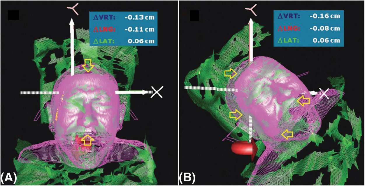
FIGURE 5.8 Optical image guidance system (Vision RT) for real-time optical surface monitoring.
Quality Assurance
Achieving and maintaining the target localization accuracy required by stereotactic techniques requires a rigorous quality assurance program. Each modality has unique quality assurance requirements, extensively described in guidance documents developed by the AAPM (41, 42). The most fundamental test, however, is common to all modalities. The coincidence of the image guidance coordinate system and the treatment delivery coordinate system should agree to within an acceptable specification, typically 1 mm or less (43). The basic test for coincidence of the isocenter reported by the imaging system with the radiation, or treatment, isocenter is a variant of the Winston-Lutz test, in which the image guidance system is used to place a test article at the isocenter and then to use the treatment beam to assess the offset from the treatment isocenter.
IMAGING FOR TREATMENT ASSESSMENT AFTER SRS/SBRT
Assessing tumor response after SRS/SBRT can be difficult because of occurrence of early nonspecific imaging changes that can represent either recurrent or progressive tumor, or treatment-related inflammatory and/or necrotic changes. In assessing response, it is important to know the appearance of radiation-induced changes in normal tissues, and the expected timeline of their development and resolution.
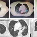
In cranial SRS, for example, underlying processes of radiation injury may cause a temporary increase in contrast enhancement on MRI, termed “pseudoprogression,” making the differentiation between true progression and radiation effects extremely difficult (44, 45) (Figure 5.9).
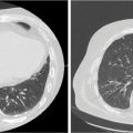
In lung SBRT, symptomatic radiopneumonitis (RP) after lung treatment is uncommon, but radiographic radiation-induced lung injury (RILI) occurs frequently, as a result of the ablative doses of RT delivered to the peritumoral region (46). With CT alone, benign changes may appear as an evolving mass-like opacity, easily mistaken for local recurrence (Figure 5.10).
A systematic review of lung SBRT has identified certain radiographic high-risk features (HRFs) suggestive of recurrence after treatment (47). These included enlargement after 12 months and craniocaudal growth of ≥5 mm and ≥20%. The presence of three or more HRFs predicted local recurrence with high sensitivity and specificity (over 90%).
Functional imaging by FDG-PET can complement suspicious CT findings, although FDG avidity can appear transiently following SBRT and even persist at a low value for over 12 months (48). Although the data are highly heterogeneous, a posttreatment SUVmax ≥5.0, or greater than the original pretreatment SUVmax, appears most suggestive of recurrent disease (48).
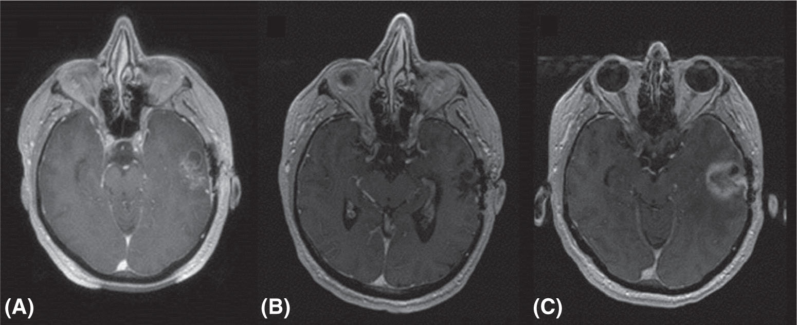
FIGURE 5.9 Pseudoprogression after cranial radiosurgery for metastatic prostate cancer: (A) pretreatment MR image; (B) 3 months after treatment; and (C) 8 months after treatment. Enhancing area is radiation necrosis rather than true progression.
Source: Courtesy of Dr. J. Engh, University of Pittsburgh Medical Center.
63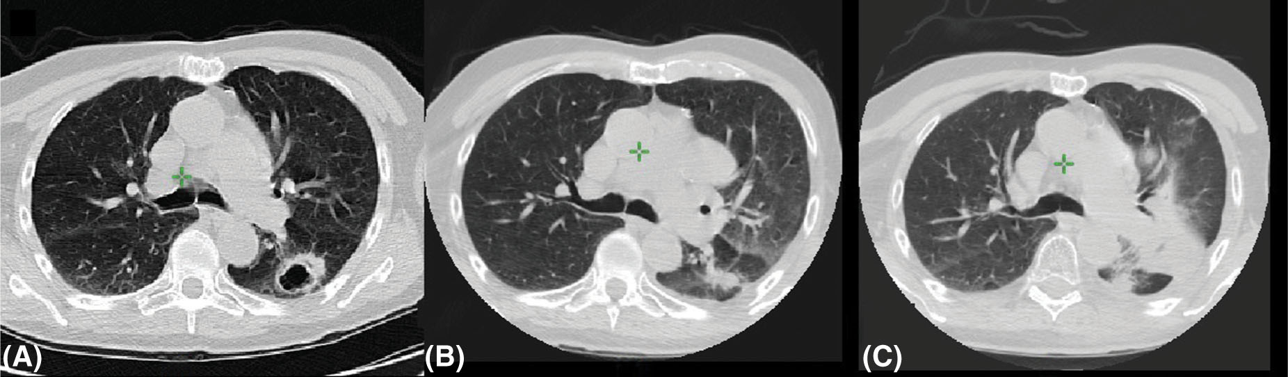
FIGURE 5.10 Radiation-induced lung injury after radiosurgery: (A) pretreatment image; (B) 4 months after treatment; and (C) 12 months after treatment.
Source: Courtesy of Dr. N. Christie, University of Pittsburgh Medical Center.
In the liver, SBRT generally results in reduced CT contrast enhancement and gradual decrease in size over 6 to 9 months. However, damage to normal liver tissue may result in complex features that make interpretation more difficult. The addition of MRI or PET imaging may provide more information when CT features are hard to interpret (49, 50).
REFERENCES
1. Ramm U, Damrau M, Mose S, et al. Influence of CT contrast agents on dose calculations in a 3D treatment planning system. Phys Med Biol. 2001;46(10):2631-2635. PubMed PMID: 11686279.
2. Huang JY, Kerns JR, Nute JL, et al. An evaluation of three commercially available metal artifact reduction methods for CT imaging. Phys Med Biol. 2015;60(3):1047-1067. doi: 10.1088/0031-9155/60/3/1047
3. Erdi YE, Macapinlac H, Rosenzweig KE, et al. Use of PET to monitor the response of lung cancer to radiation treatment. Eur J Nucl Med. 2000;27(7):861-866. PubMed PMID: 10952499.
4. Beyer T, Townsend DW, Brun T, et al. A combined PET/CT scanner for clinical oncology. J Nucl Med. 2000;41:1369-1379. PubMed PMID: 10945530.
5. Kim J, Garbarino K, Schultz L, et al. Dosimetric evaluation of synthetic CT relative to bulk density assignment-based magnetic resonance-only approaches for prostate radiotherapy. Radiat Oncol. 2015;10:239. doi: 10.1186/s13014-015-0549-7
6. Otazo R, Kim D, Axel L, et al. Combination of compressed sensing and parallel imaging for highly accelerated first-pass cardiac perfusion MRI. Magn Reson Med. 2010;64:767-776. doi: 10.1002/mrm.22463
7. Zeverino M, Jaccard M, Patin D, et al. Commissioning of the Leksell Gamma Knife® Icon™. Med Phys. 2017;44(2):355-363. doi: 10.1002/mp.12052.
8. Daisne JF, Blumhofer A. Atlas-based automatic segmentation of head and neck organs at risk and nodal target volumes: a clinical validation. Radiat Oncol. 2013;8:154. doi: 10.1186/1748-717X-8-154
9. Murphy MJ. An automatic six-degree-of-freedom image registration algorithm for image-guided frameless stereotaxic radiosurgery. Med Phys. 1997;24(6):857-866. doi: 10.1118/1.598005
10. Mayyas E, Chetty IJ, Chetvertkov M, et al. Evaluation of multiple image-based modalities for image-guided radiation therapy (IGRT) of prostate carcinoma: a prospective study. Med Phys. 2013;40:041707. doi: 10.1118/1.4794502
11. Benedict SH, Yenice KM, Followill D, et al. Stereotactic body radiation therapy: the report of AAPM Task Group 101. Med Phys. 2010;37:4078-4101. doi: 10.1118/1.3438081
12. Yin F-F, Wong J, Balter J, et al. The Role of In-Room kV X-Ray Imaging for Patient Setup and Target Localization Report of AAPM Task Group 104. College Park, MD: American Association of Physicists in Medicine; 2009.
13. De Los Santos J, Popple R, Agazaryan N, et al. Image guided radiation therapy (IGRT) technologies for radiation therapy localization and delivery. Int J Radiat Oncol Biol Phys. 2013;87:33-45. doi: 10.1016/j.ijrobp.2013.02.021
14. Bissonnette JP, Moseley D, White E, et al. Quality assurance for the geometric accuracy of cone-beam CT guidance in radiation therapy. Int J Radiat Oncol Biol Phys. 2008;71:S57-S61. doi: 10.1016/j.ijrobp.2007.06.086
15. Chang J, Yenice KM, Narayana A, et al. Accuracy and feasibility of cone-beam computed tomography for stereotactic radiosurgery setup. Med Phys. 2007;34:2077-2084. doi: 10.1118/1.2731031
16. Foster RD, Pistenmaa DA, Solberg TD. A comparison of radiographic techniques and electromagnetic transponders for localization of the prostate. Radiat Oncol. 2012;7:101. doi: 10.1186/1748-717X-7-101
17. Schewe JE, Lam KL, Balter JM, et al. A room-based diagnostic imaging system for measurement of patient setup. Med Phys. 1998;25:2385-2387. doi: 10.1118/1.598461
18. Chang SD, Murphy MJ, et al. The Cyberknife: a frameless robotic system for radiosurgery. Stereotact Funct Neurosurg. 1997;69:124-128. doi: 10.1159/000099863
19. Jin JY, Yin FF, Tenn SE, et al. Use of the BrainLAB ExacTrac X-Ray 6D system in image-guided radiotherapy. Med Dosim. 2008;33:124-134. doi: 10.1016/j.meddos.2008.02.005
20. Verellen D, Soete G, Linthout N, et al. Quality assurance of a system for improved target localization and patient set-up that combines real-time infrared tracking and stereoscopic X-ray imaging. Radiother Oncol. 2003;67:129-141. PubMed PMID: 12758249.
21. Gevaert T, Verellen D, Tournel K, et al. Setup accuracy of the Novalis ExacTrac 6DOF system for frameless radiosurgery. Int J Radiat Oncol Biol Phys. 2012;82:1627-1635. doi: 10.1016/j.ijrobp.2011.01.052
Related posts:

Stay updated, free articles. Join our Telegram channel

Full access? Get Clinical Tree


