Diagnostic imaging has become critical in the care of patients suffering from traumatic or nontraumatic emergent orbital conditions. Multidetector computed tomography (MDCT) has become the standard imaging modality for assessing orbital trauma because of its accurate assessment of orbital skeletal and soft tissues injuries. Contrast-enhanced MR imaging is the first-line examination in the assessment of nontraumatic orbital conditions given its excellent evaluation of the orbital soft tissues. Conventional angiography is necessary in some vascular orbital complications and allows for endovascular treatment. This article discusses the spectrum of orbital pathology encountered in the imaging of orbital trauma and nontraumatic orbital emergencies.
Key points
- •
Multidetector computed tomography (MDCT) has become a crucial component in the assessment of orbital trauma.
- •
MDCT allows for accurate characterization of the orbital fractures, orbital soft tissue injuries, and assessment of orbital foreign bodies.
- •
Nontraumatic orbital emergencies often present a challenge to clinical diagnosis due to overlapping symptomatology necessitating radiological evaluation.
- •
Contrast-enhanced MR imaging allows for detailed evaluation of the orbital soft tissues and differentiation of the multiple causes of nontraumatic orbital emergencies.
- •
Conventional angiography is useful for the diagnosis and treatment of vascular orbital emergencies, such as carotid–cavernous fistulae.
Introduction
Radiological imaging evaluation is crucial in the aid of clinical assessment in patients with orbital trauma or nontraumatic orbital emergencies. In the setting of orbital trauma, clinical assessment of the orbits may be hindered by extensive facial soft tissue injury, decreased level of consciousness, or life-threatening injuries to the remainder of the body. Multidetector computed tomography (MDCT) is the modality of choice in the assessment of orbital trauma because of its many advantages over other imaging modalities. MDCT is superior to conventional radiography due to its faster acquisition; it may be performed concomitantly with CT imaging of additional body parts frequently obtained in the setting of multi organ injuries. Additionally, it only requires 1 head position, and it allows for the assessment of the orbital soft tissues, is more sensitive for detection of fractures, and may be reformatted in multiple projections and in 3 dimensions. Ultrasound is user dependent and contraindicated in the setting of suspected open globe injury. MR imaging cannot be performed in the setting of potential intraorbital metallic foreign body.
Patients also seek emergency care for many nontraumatic orbital conditions causing a multitude of presenting symptoms to include: vision loss, scotoma, eye pain, ophthalmoplegia, diplopia, orbital bruit, proptosis, or enophthalmos. Cross-sectional imaging with either contrast-enhanced MR imaging or MDCT is helpful in differentiating the numerous etiologies of disease states that present with these symptoms. MR imaging is particularly useful in the setting of nontraumatic emergencies due to its superior evaluation of the orbital soft tissues with respect to MDCT. In addition, conventional angiography may be indicated in select cases in which a vascular abnormality affecting the orbit is suspected, such as carotid–cavernous fistulae. Although invasive, conventional angiography has advantages over CT angiography (CTA) and magnetic resonance angiography (MRA), as it consists of real-time imaging and allows for endovascular treatment when appropriate.
Orbital skeletal trauma
Orbital Blowout Fracture
Orbital blowout fracture is a displaced fracture of an orbital wall directed away from the orbit, which may be characterized as pure, if the orbital rim is spared, or impure, if the orbital rim is involved in the fracture ( Fig. 1 ). The 2 mechanisms of the orbital blowout fracture are termed the hydraulic and the bone conduction mechanisms, which both have shown to result in orbital blowout fractures in experimental models with key differences ( Box 1 ). The inferior orbital wall is most frequently affected by the blowout fracture, followed by the medial orbital wall. Although the medial orbital wall (lamina papyracea) is thinner than the inferior orbital wall, it is supported by osseous struts of the ethmoid sinuses, likely increasing its durability against fracture. Complications that advocate for early surgical repair include extraocular muscle entrapment and enophthalmos, which are typically seen in fracture fragments of greater than 1 cm in size. Internal fixation of orbital blowout fracture typically results in the placement of mesh material to restore orbital volume and provide a barrier against the herniation of intraorbital contents.
- •
Hydraulic mechanism—posteriorly oriented force to the orbit causes an acute increase in intraorbital pressure with subsequent fracture of the weakest orbital wall to relieve this pressure.
- ○
Larger fracture defect
- ○
May affect the medial orbital wall
- ○
Commonly results in herniation of orbital contents
- ○
- •
Bone conduction mechanism—a force applied to the orbital rim is transmitted posteriorly until eventual buckling of the affected wall occurs.
- ○
Smaller, anterior fracture defect
- ○
Never involves medial wall
- ○
Rarely results in herniation
- ○
A special type of the orbital blowout fracture is the trapdoor fracture. The trapdoor fracture is an inferior orbital blowout fracture in which the inferior rectus muscle or infraorbital fat herniates through the fracture defect into the underlying maxillary sinus with return of the fracture fragment back to its original position; thus, the fracture fragment acts like a trapdoor. These patients will present with signs of entrapment caused by extraocular muscle restriction, resulting in diplopia. On coronal CT imaging, the inferior rectus muscle or extraconal fat herniates inferior to the orbital floor through a nondisplaced inferior orbital wall fracture.
Superior Orbital Wall Fracture
The superior orbital wall or orbital roof is the only wall that forms a partition between the anterior cranial fossa and intraorbital contents. Fractures through the orbital roof are typically a result of a direct blow to the forehead and usually displace into the orbit, termed orbital blow-in fracture ( Fig. 2 ). Associated frontal sinus fracture is a common finding. Potential complications include proptosis, diplopia, orbital emphysema, dural tear with resultant cerebrospinal fluid (CSF) leak or brain herniation, cerebral contusion, and extension of fracture to the orbital apex. Repair of these potential complications may require both intracranial and extracranial approaches. The fractures are best visualized on coronal reformatted CT images.
Zygomaticomaxillary Complex Fracture
Zygomaticomaxillary complex (ZMC) fracture is caused by a direct traumatic blow to the malar eminence, resulting in diastasis through the 4 sutures that attach the zygoma to the remaining face and calvarium ( Fig. 3 ). Historically, this fracture pattern was described by the misnomer tripod fracture, as a fracture through the zygomaticofrontal, zygomaticomaxillary, and zygomaticotemporal sutures could be discerned by conventional radiography. However, fracture additionally extends through the zygomaticosphenoid suture. The zygoma forms portions of the inferior and lateral orbital walls, anterior and posterolateral maxillary sinus walls, and zygomatic arch. Displaced ZMC fractures that rotate along the axis of the zygomaticosphenoid suture or concomitant orbital floor blowout fractures can result in enophthalmos, which may necessitate intraorbital reconstruction in addition to ZMC fracture fixation.
Naso-Orbitoethmoid Complex Fracture
Naso-orbitoethmoidal (NOE) complex fracture is caused by posteriorly oriented high-impact force applied to the nasal region with transmission through the nasal cavity, medial orbital walls, and ethmoid sinuses ( Fig. 4 ). This fracture complex typically results in severe comminution and telescoping of the bilateral nasal bones and septum, ethmoid sinuses including the cribriform plate, and medial orbital walls. Frequent complications caused by NOE fractures include proptosis due to a decrease in intraorbital volume, telecanthus from a medial canthal tendon injury, and CSF rhinorrhea caused by fracture through the cribriform plate and tear of the apposed dura. The Markowitz and Manson classification system separates NOE fracture complexes by comminution of the lacrimal fossa and involvement of the medial canthal tendon into 3 types ( Box 2 ). Since the medial canthal tendon is not seen by CT, description of the degree of comminution of the medial orbital wall at the expected attachment of the medial canthal tendon in the lacrimal fossa is helpful in surgical planning of potential medial canthal tendon repair.
- •
Type I—medial canthal tendon intact and connected to single large fracture fragment
- •
Type II—medial canthal tendon intact and connected to single fragment of comminuted fracture
- •
Type III—medial canthal tendon disrupted with comminuted fracture of the lacrimal fossa
LeFort Complex Fractures
At the turn of the twentieth century, the French surgeon Rene LeFort described 3 types of midface fracture patterns resulting in varying degrees of craniofacial dissociation that resulted from high-impact forces applied to the midface of cadavers ( Fig. 5 ). Disruption of the pterygomaxillary junction is the commonality shared by the 3 patterns, and it must be present to characterize a fracture pattern as a LeFort fracture. Although the 3 types of complex fracture patterns described by LeFort were characterized separately and symmetrically across the midface, these fracture patterns may be seen concomitantly and/or asymmetrically involving the 2 halves of the midface. Each of the LeFort fracture types affects unique portions of the midface, which can simplify characterization ( Box 3 ). The LeFort type I fracture complex does not involve the orbit and will therefore not be discussed.
- •
Type I—lateral margin of nasal fossa and inferior nasal septum
- •
Type II—inferior orbital rim
- •
Type III—lateral orbital rim and zygomatic arch
LeFort type II fracture complex, also known as the pyramidal fracture, results in a pyramid-shaped fracture of the central midface that may move independently from the remaining lateral face and skull base. Fracture extends obliquely inferolaterally from the nasofrontal suture (apex of pyramid) through the medial orbital walls, orbital floors, and maxillary sinus walls along the zygomaticomaxillary sutures. Involvement of the inferior orbital walls is unique to the LeFort type II fracture complex. Axial and coronal reformatted CT images enable detection of the obliquely oriented fractures extending through the medial and inferior orbital walls.
LeFort type III fracture complex produces true craniofacial dissociation. Fracture extends from the nasofrontal suture laterally through the medial orbital walls, lateral orbital walls, and zygomatic arches. Using axial and coronal reformatted CT images to detect extension of fracture through the zygomatic arch is unique to the LeFort III fracture complex, and is therefore a helpful discriminator in distinguishing between LeFort II and III fracture complexes, which both share fracture components through the nasofrontal suture and medial orbital walls.
Orbital Apex Fracture
Fractures of the orbital apex can extend through the optic canal or superior orbital fissure, resulting in damage to the cranial nerves that traverse these structures ( Fig. 6 ). Fracture through the optic canal may result in monocular blindness from optic nerve injury caused by direct impaction from fracture fragments or subsequent compression from resultant edema or hemorrhage. In complex trauma patients in whom vision cannot be clinically assessed as a result of extensive soft tissue swelling or obtundation, detection of orbital apex fracture by MDCT may be the only method to diagnose potential vision-compromising injury.
Two clinical syndromes may develop as a result of orbital apex fractures, the superior orbital fissure syndrome, and the orbital apex syndrome. The superior orbital fissure syndrome is caused by fracture-related injury to cranial nerves III, IV, V 1 , and VI as they traverse the superior orbital fissure, thus causing ophthalmoplegia, diplopia, and ptosis. The addition of injury to the optic nerve at the orbital apex is termed the orbital apex syndrome, and would add monocular vision loss to the patient’s symptoms. On CT, special attention is needed to assess the fat about the intracanalicular optic nerve in the setting of fracture. Any soft tissue attenuation along the optic nerve should be deemed suspicious for potential edema or hemorrhage within the confined space of the optic canal. On MR imaging, replacement of the normal T1 hyperintense fat within the optic canal or abnormal T2 hyperintensity within the optic canal or adjacent optic nerve also correlates to the injury. Injury to the optic nerve at the orbital apex is an emergency that may prompt high-dose steroid therapy or potential surgical decompression to prevent permanent blindness.
Traumatic globe injury
Ocular Hemorrhage and Detachments
Blunt and penetrating injury to the globe can result in several ocular hemorrhage patterns that are distinguishable on cross-sectional imaging ( Fig. 7 A). Hyphema, hemorrhage within the anterior chamber of the globe, is recognized on CT as layering hyperdensity anterior to the lens. Although hyphema is easily recognized by clinical examination and often does not require radiological diagnosis, it should prompt the radiologist to pay close attention to the posterior segment, as ophthalmoscopic examination is compromised from the intervening anterior chamber blood products.
Vitreal hemorrhage, hemorrhage within the vitreous, demonstrates heterogeneous hyperdensity as blood products mix with the vitreous humor on CT ( Fig. 7 B). Subhyaloid hemorrhage, hemorrhage external to the hyaloid membrane that covers the vitreous and separates it from the retina, is defined on CT by a layer of hyperdensity that usually pools anterior to and covers the optic disc with a sharp margin between the subhyaloid hemorrhage and vitreous (see Fig. 7 A).
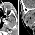
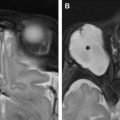
Retinal detachment, hemorrhage or fluid between the retina and choroid or between layers of the retina resulting in separation of these layers, is characterized on imaging by lentiform-shaped collections ( Fig. 8 A). The retina extends to, but not across, the optic disc; thus diffuse retinal detachment gives a V-shaped appearance on axial cross-sectional images with apex at the optic disc. Choroidal melanoma is a potential malignant cause of spontaneous retinal detachment and will appear as a mushroom-shaped enhancing mass extending from the ocular wall into the vitreous ( Fig. 8 B).
Related posts:


Stay updated, free articles. Join our Telegram channel

Full access? Get Clinical Tree


