Fig. 1.
Principle of the reconstitution of membrane proteins by direct incorporation within supported lipid bilayer. (a) Direct incorporation of membrane proteins in SLB. (1) Incubation of solubilized membrane proteins with detergent that partition between the aqueous phase and the SLB, and destabilize the latter. (2) Unidirectional incorporation of membrane proteins in SLB. (3) Detergent removal by extensive rinsing before AFM imaging. (b) Sample preparation and imaging. Bilayers are formed on a mica disk glued with Araldite® on a Teflon pad that prevents any buffer leakage during incubation with vesicles and AFM imaging. This Teflon pad is glued at the top of a metal disk that is fixed on the AFM scanner head.
3.1 Artificial Supported Lipid Bilayers
3.1.1 Preparation
Different methods have been developed to prepare SLB but the most popular remains the formation of supported membranes by fusion of large unilamellar lipid vesicles (LUVs) on a solid surface (20). LUVs are generally prepared via sonication or extrusion and the vesicle solution is then added on top of the support. Vesicles then adsorb on the substrate before rupturing. Formation of a continuous supported bilayer is a prerequisite to perform efficient incorporation of transmembrane proteins, allowing easier tuning of detergent concentration (see below) and a better reproducibility of experiments. We often use phase-separated lipids bilayer, (e.g., DOPC/DPPC SLBs), in order to assess the formation of a continuous membrane (phase separation is easily observed with AFM (21)). The main steps of the protocol are:
1.
Glue a Teflon pad, which prevents any buffer leakage during incubation with vesicles and AFM imaging, at the top of a metal disk that will be later fixed on the AFM scanner head. A mica disk is then glued with Araldite® at the top of this Teflon pad.
2.
Dry the lipids that were solubilized in organic solvent under nitrogen flow in a Pyrex® tube at 30°C using a dry block for at least 2 h. If a lipid mixture is used, vortex the tube before drying.
3.
Suspend the dried lipids at 0.125 mM in PBS buffer by 1 min strong vortexing under argon in the presence of 2 mm glass beads to form multilamellar vesicles (MLV). Alternatively, longer vortexing without beads can be used.
4.
Extrude MLVs using a suitable extruder (e.g., Avanti Mini-Extruder) through a 100 nm diameter polycarbonate membrane to produce LUVs. Their homogeneity can be easily controlled using dynamic light scattering.
5.
Cleave the mica disk, deposit LUVs onto it (see Fig. 1b) and allow the LUVs to adsorb and fuse during 2 h incubation. Perform the incubation at a temperature 20°C above the fusion temperature of the lipids allowing them to form a homogeneous fluid phase.
6.
Before AFM imaging, wash away non-fused vesicles by successive exchange of buffer.
7.
Add 50 μl of PBS buffer to bathe the SLB before detergent destabilization and protein incorporation.
The procedure described above leads to a flat supported lipid bilayer with a root mean square (rms) in the Angstrom range (see an example in Fig. 2a), a big advantage for high-resolution imaging as compared to polymer-supported bilayers that are more corrugated.
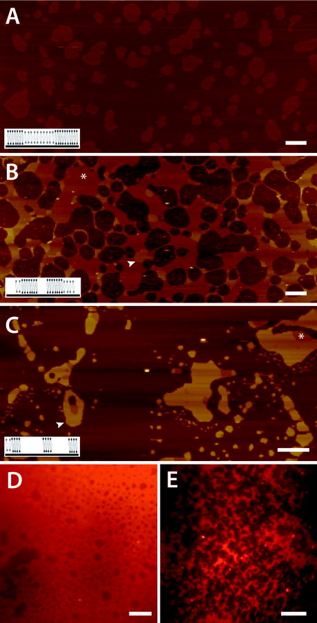
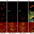
Fig. 2.
AFM imaging of supported lipid bilayers and control of detergent destabilization conditions. (a) Topography image of 30 μm AFM scan of a DOPC/DPPC SLB deposited on mica (z scale 25 nm). DPPC gel phase domains with a size in the micrometer range (lighter brown) protrude ∼1 nm from the fluid DOPC phase. The reason for the different height between the two lipid phases is schematized in the small cartoon showing extended fatty Fig. 2. (continued) acid chains for DPPC lipids (in black) and relaxed chains for DOPC (in grey). (b) Topography of DOPC/DPPC bilayer (z scale, 20 nm) after incubation with the low cmc glycosylated detergent DOTM at 0.075 mM (1.5× cmc). Brown areas correspond to solubilized membranes. Both fluid (white asterisk) and gel (white arrowhead) can still be observed. (c) Topography image of DOPC/DPPC bilayer (z scale, 20 nm) incubated with the high cmc detergent OG. The membrane is mainly solubilized and gel phase is only preserved (white arrowhead and see the inset). Some tiny fluid domains are sometimes observed (white asterisk). (d and e) Fluorescence image of DOPC/DPPC bilayer recorded with an upright microscope, equipped with a 10× long working distance objective, before (d) or after (e) incubation with 0.2 mM DDM. The darker round-shaped domains in (d) correspond to DPPC gel phase domains (most of the lipid fluorescent probe partition in the fluid phase). The dark areas in (e) correspond to solubilized membranes. Scale bars are 2 μm (a) and 1 μm (b and c) and 40 μm (d and e).
It is really important that a water layer with a thickness ranging from 1 to 3 nm separates the bilayer from the substrate (reviewed in ref. 22, 23) and insures SLBs to have the essential feature of free-standing membranes as demonstrated by measuring lipid diffusion using fluorescence recovery after photobleaching (20) or fluorescence correlation spectroscopy (FCS) (24, 25) (see Note 1).
3.1.2 Imaging
1.
Use AFM contact mode for SLB imaging.
2.
Minimize tip-sample interaction by tuning buffer composition (e.g., 10 mM Tris–HCl, 150 mM KCl, pH 7.4) and the spring constant of the cantilever, which must be small in the 10–200 mN/m range.
3.
Make sure that the tip applies a force on the membrane below 100 pN, due to membrane softness.
4.
Because AFM scanners are limited to a few tens of micrometers, it can be useful to control SLBs coverage on a large scale using fluorescence microscopy. Lipid phase separation and non-covered areas can be easily observed with an upright microscope by adding a small amount (<0.5%) of lipid fluorescent probe during the preparation of lipid solution (Fig. 2d).
3.2 Tuning Membrane Destabilization with Detergent
3.2.1 Preparation
A key point of the method is the formation of specific defects in SLB to allow the insertion of solubilized proteins. The rationale is to tune the detergent concentration to form these defects in the SLB but to limit membrane solubilization. We have found that successful insertion of proteins is obtained when SLBs are destabilized by low cmc detergents such as n-dodecyl-β-D-maltopyranoside (DDM, 0.17 mM cmc), n-dodecyl-β-D-thiomaltopyranoside (DOTM, 0.05 mM cmc), or Fos-Choline C16 (F16, 0.013 mM cmc). These detergents are mild detergents and routinely used for the purification of membrane proteins. Other detergents including high cmc detergents like n-octyl-β-d-glucopyranoside or LDAO or other non-glycosylated low cmc detergents including Triton X-100 or C12E8 lead to an almost complete solubilization of the SLBs, at least under the experimental conditions described below, and should be avoided if possible (the pattern of solubilization is close to that described in Fig. 2c; see also ref. 9, 10). The following protocol has been successfully used:
2.
Prepare 50 μl of a detergent-containing buffer with detergent concentration of 0.6 mM, 0.15 mM, or 0.26 mM for DDM, DOTM, or F16, respectively (see Note 2).
3.
Carefully remove 25 μl from the 50 μl of PBS buffer bathing the SLB.
4.
Add 25 μl of the detergent solution to the SLB and mix by up-and-down pipeting. The final detergent concentration is 0.3 mM (1.7× cmc), 0.075 mM (1.5× cmc), or 0.13 mM (10× cmc, at 4°C) for DDM, DOTM, or F16, respectively. In the case of a new detergent, incubate SLBs with detergent at final concentrations slightly above the cmc, e.g., 1.05×, 1.2×, and 1.5× cmc.
5.
Incubate for 15 min at room temperature to allow the equilibration of the detergent.
6.
Remove detergent by gently rinsing with at least 10 drops of detergent-free PBS buffer and repeat this step at least 3 times with 20 min time intervals to favor the exchange between SLB and buffer.
3.2.2 Imaging
Before AFM imaging, it is necessary to wait a few hours, the time required for membrane equilibration. It is also worth noting that topographs of SLB in the presence of detergent cannot be recorded due to the instability of the signal due to membrane remodeling. As shown in Fig. 2b, a low detergent concentration leads to a good preservation of both fluid and gel phase even if the membrane is largely remodeled and partially solubilized (Fig 2b). The percentage of solubilization should be below 50%. Further increase of the detergent concentration leads to, first, almost complete solubilization of the fluid phase (since it is less resistant than the rigid gel phase domains) (Fig. 2c), and, second, to complete lipid solubilization producing free regions of mica devoid of material (data not shown). Thus, we hypothesize that SLBs after detergent removal are representative of SLBs in the presence of detergent. Although this is a simplistic approximation, this allows proposing experimental guidelines for the following protein incorporation described in Subheading 3.3.
In addition to AFM imaging, optical microscopy can be used to determine the percentage of remaining membrane. In this case, SLB are previously doped with 0.5% fluorescent lipid (e.g., 1,2-dioleoyl-sn-glycero-3-phosphatidylethanolamine labeled with rhodamine on the polar head) that mixes with fluid phase and is excluded from the gel phase. Representative images show a continuous fluorescence with dark areas corresponding to gel phase domains (Fig. 2d). After detergent incubation and removal, fluorescent fluid phase domains are still observed (Fig. 2e). It is worth noting that most of the fluorescent probes partition in the fluid phase and it is then difficult to discriminate between gel phase domains and solubilized membranes. However, the former is generally round shaped whereas the later is more heterogeneous in size and reveals recognizable features of the detergent/SLB interactions (compare Fig. 2d, e).
3.3 Incorporation of Transmembrane Proteins
3.3.1 Incorporation of LH1–RC
Incorporation of membrane proteins is performed at the detergent concentration that has been defined in Subheading 3.2, always higher than the cmc to preserve the solubility of the protein. Proteins are generally purified after membrane-solubilization with low cmc detergents. We describe below the protocol used for the incorporation of LH1–RC, which can be adapted for other membrane proteins as well:
2.
Carefully remove 25 μl from the 50 μl of PBS buffer bathing the SLB.
3.
Add 25 μl of buffer containing detergent and proteins at a concentration of 0.150 mM DOTM and 10–100 μg/ml protein (i.e., 0.5–5 μg, 1–10 pmol proteins per assay) (see Notes 3 and 4).
4.
 Introduction: Nanoimaging Techniques in Biology
 Two-Color STED Imaging of Synapses in Living Brain Slices
 Secondary Ion Mass Spectrometry Imaging of Biological Membranes at High Spatial Resolution
 Functional AFM Imaging of Cellular Membranes Using Functionalized Tips
 Correlative Optical and Scanning Probe Microscopies for Mapping Interactions at Membranes
 Nanoimaging Cells Using Soft X-Ray Tomography


Gently mix by up-and-down pipeting of the solution.
Related posts:
Introduction: Nanoimaging Techniques in Biology
Two-Color STED Imaging of Synapses in Living Brain Slices
Secondary Ion Mass Spectrometry Imaging of Biological Membranes at High Spatial Resolution
Functional AFM Imaging of Cellular Membranes Using Functionalized Tips
Correlative Optical and Scanning Probe Microscopies for Mapping Interactions at Membranes
Nanoimaging Cells Using Soft X-Ray Tomography
Stay updated, free articles. Join our Telegram channel
Full access? Get Clinical Tree
