Chapter 2 Imaging planes
Long axis: two-chamber view (LV)
Long axis: two-chamber view (RV)
Short axis: left ventricular view
Right ventricular outflow view
Imaging planes
Body imaging planes
The first sets of planes to become familiar with are those that divide up the body. These are best described by assuming that the body is standing upright and facing towards you. Any particular plane can occur at any point through the body along the axis of the plane, and therefore is also usually referenced according to some anatomical landmark (e.g a vertebral body) or distance from that landmark. The basic planes can be described as follows.
 Transverse—these are horizontal planes, the classic cross-sectional CT view (Fig. 2.1). They can be referenced to a landmark, although in some imaging modalities the images are labelled according to fixed points within the scanner. When displayed they are viewed as if looking from the feet.
 Coronal—up and down, with the body cut from left to right, as if looking straight at the whole body (Fig. 2.1). The classic coronal view is the view of the two hemispheres of the brain or a slice through both kidneys.
 Sagittal—up and down, with the body cut from front to back (Fig. 2.1). The classic sagittal view is the slice down the vertebral column.
 Oblique sagittal—as for sagittal but at a slight angle from the true front to back axis. The classic oblique sagittal view is the slice through the arch and descending aorta.
Cardiac imaging planes
Body image planes allow an overview of anatomy. The standard structures of the heart are not clearly displayed with these imaging planes and therefore there are additional cardiac imaging planes. Fortunately, the same planes are used across modalities, although they often have slightly different names between modalities. They can be grouped into four broad groups.
 Long axis—these lie along the long axis of the structure you are interested in i.e. the plane that gives the longest dimension of the object. For example a long axis of the heart is (an axis parallel to the septum that passes through the apex) These views provide information on cardiac chambers and valve leaflets and include the apical fourchamber view or left ventricular outflow view
 Short axis—these planes lie roughly perpendicular to the long axis at the structure you are interested in and display the heart in cross section. They can lie at any point in the heart to highlight particular structures (e.g. short axis of the left ventricle, aortic valve, or mitral valve).
 Miscellaneous—a range of specialized views that have been developed to allow particular structures to be seen such as the atrial septum or pulmonary veins.
 Polar—these are designed to display the whole left ventricle as a map with the apex at the centre.
Coronary imaging planes are distinct from other imaging modalities and therefore are discussed separately in the section on this imaging modality, page 8. Chest X-ray is essentially a coronal view of the chest.
Fig. 2.1 Cardiovascular magnetic resonance pilot images demonstrating transverse (top), coronal (middle), and sagittal (bottom) planes.

Long axis: four-chamber view
This allows assessment of overall left and right ventricular function as well as right and left ventricular inflow.
Names
 Echo—apical four-chamber view
 TOE—0° four chamber view
 CMR—horizontal long axis (HLA)
 CT—not often acquired
 Nuclear—four chamber long-axis view
The view (Fig. 2.2)
The optimal image should extend from the apex (the true apex is identified by the fact that it moves less than the other walls and is thinner). In a true unforeshortened view the left ventricle will be at its longest. Both ventricles, both atria, and both mitral and tricuspid valves should be visible. Septa should be straight down the centre of the image.
Sometimes it is difficult to get both the atria and the ventricles in full view. In this case the image can be optimized based on the area of the heart of interest, usually the ventricles.
What do you see?
Mitral valve
A2 and P2 segments of mitral valve are seen, which allow assessment of movement. Lateral and septal mitral valve annulus is also visible.
Tricuspid valve
Lateral and septal leaflets displayed.
Left and right atrium
Both atria and the inter-atrial septum can be seen. Pulmonary veins as well as vena cavae may also be visible. Can be used to measure atrial size.
Left ventricle
Key view for studying global and regional left ventricular function. Septum, apex, and lateral wall are displayed.
Right ventricle
A key view for looking at the right ventricle size and function. Usually compared with the left ventricle, but quantitative measures are also possible.
Pericardium
Important view for seeing size and location of pericardial fluid.
Fig. 2.2 Four-chamber (or horizontal long-axis) views of the heart.
Long axis: five-chamber view
Used to look at the left ventricular outflow and the aortic valve.
Names
 Echo—apical five-chamber view
 TOE—0° five-chamber or 0° deep transgastric view
 CT/nuclear—not often acquired
 CMR—usually acquired as a three chamber LVOT view (p. 74)
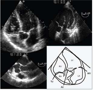
The view (Fig. 2.3)
The optimal image looks similar to that obtained with the long-axis four-chamber view, but adjusted to include the aortic valve and ascending aorta.
What do you see?
Aortic valve
Right and non-coronary cusps (although they may not be easy to see).
Left ventricular outflow tract
During echocardiography used with colour flow mapping for aortic regurgitation or flow turbulence due to obstruction. Best view to place pulsed wave Doppler to assess outflow and obstruction.
Fig. 2.3 Echocardiographic five chamber view demonstrating transthoracic (top left), 0° in oesophagus (bottom left), and deep transgastric transoesophageal (top right) echocardiography.
Long axis: two-chamber view (LV)
An important view for global and regional left ventricular assessment.
Names
 Echo—Apical two chamber view
 TOE—90° two-chamber or transgastric 90° view
 CMR—vertical long-axis (VLA) view
 Nuclear—two-chamber long-axis view
 CT—not often acquired
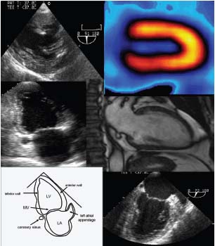
The view (Fig. 2.4)
The optimal image shows the left ventricle (no right ventricle) from the apex, centred in the image. The mitral valve is cut through the commissure. The left atrium is seen with left atrial appendage visible.
What do you see?
Left ventricle
Inferior wall and anterior wall (closest to left atrial appendage). Good for regional assessment. Used for ventricular volume and function measures.
Mitral valve
The ideal image is a commissural view with P3, A2, and P1 segments visible. It is possible to assess the long axis of the mitral valve annulus.
Left atrial appendage
This is sometimes visible as a curved finger pointing round the side of the mitral valve.
Coronary sinus
The coronary sinus is usually seen in cross section on the opposite side of the mitral valve from the left atrial appendage.
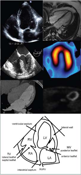
Fig. 2.4 Two-chamber (or vertical long-axis) views of the heart. TOE transgastric (top left) nuclear perfusion (top right) transthoracic (middle left), CMR (middle right), TOE oesophageal (bottom right).
Long axis: two-chamber view (RV)
This view is used to assess right ventricular appearance.
Names
 Echo—apical two-chamber view of right ventricle
 TOE—Transgastric 90° RV two-chamber view
Stay updated, free articles. Join our Telegram channel

Full access? Get Clinical Tree


